Badger Meter MDS 2000 User Manual
Oil management system
Hide thumbs
Also See for MDS 2000:
- Installation and software manual (48 pages) ,
- User manual (66 pages)
Table of Contents
Advertisement
Quick Links
Download this manual
See also:
User Manual
Advertisement
Table of Contents

Related Manuals for Badger Meter MDS 2000


Summary of Contents for Badger Meter MDS 2000
- Page 1 ® Badger Meter Europa GmbH MDS 2000 Oil Management System USER MANUAL March 2012 Firmware v7.38 LMS_MDS2000_BA_02_1203...
-
Page 2: Table Of Contents
Contents 1. Basic safety recommendations ..................1 2. Overview ..........................2 Product description ..................... 2 Schematic overview ....................3 3. Functional description ...................... 4 4. The keypad interface ......................5 5. Start-up ..........................5 6. Accessing the system ....................... 6 7. - Page 3 Contents 11.8 Ticket location ......................22 11.9 Change system PIN ....................23 11.10 Set pulses per unit ....................23 11.11 Maximum dispenses ....................23 11.12 Hose display setup ....................24 11.13 Set decimal places ....................24 11.14 Hose calibration ..................... 24 11.15 Set I/O network ID ....................
-
Page 4: Basic Safety Recommendations
Basic safety recommendations page 1/42 1. Basic safety recommendations Before installing or using this product, please read this instruction manual thoroughly. Only qualified personnel should install and/or repair this product. In case of problems, please contact your distributor. Installation Do not place any unit on an unstable surface that may allow it to fall. Never place the units above a radiator or heating unit. -
Page 5: Overview
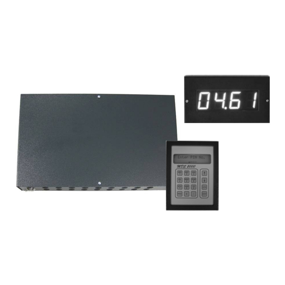
Overview page 2/42 2. Overview Product description A typical system will consist of one or more control modules called I/O units and one or more user entry devices called keypads. An I/O unit provides control for the fluid. It controls a number of solenoid valves to start and stop dispenses by using information from flow meters in the fluid lines. -
Page 6: Schematic Overview
Overview page 3/42 Schematic overview Network PC software Report printer Validation RS232 Server - Host DMS system CAN Bus RS232 Interface box I/O Control unit Power users max. supply I/O control units max. keypads max. 128x 8x per unit meters max. -
Page 7: Functional Description
Functional description page 4/42 3. Functional description The basic function of the system is to control the amount of fluid being dispensed. The system implements this function by considering various user parameters. Initially, a technician must log onto the system by entering his assigned PIN. The technician is then prompted to enter various parameters, which can include job number, registration number and odometer reading. -
Page 8: The Keypad Interface
The keypad interface / Start-up page 5/42 4. The keypad interface All operations are usually done using the keypad operator interface. Below is a diagram showing the layout of a keypad. The keypad is laid out similar to that of a mobile phone. Numeric data can be directly entered. -
Page 9: Accessing The System
Start-up / Accessing the system page 6/42 When a keypad is powered on, the display shows the version number of the keypad firmware, the date and the keypad network ID. Once the keypad has established the communication with its controlling I/O, the screen is updating. The new screen will be the one that the keypad was last displaying when the power was switched off. -
Page 10: System Principles
System principles page 7/42 7. System principles Dispensing principles The MDS2000 system controls the flow of fluid by opening and closing a valve in the fluid line. The amount of fluid dispensed is measured by a flow meter. When the system is dispensing, the MDS2000 opens the valve. -
Page 11: Preselect Dispensing Mode
System principles page 8/42 Preselect dispensing mode The diagram below shows the sequence of events for a preselected dispense. The order of events are as follows: Master Valve Master valve 1) The pump air solenoid (or master valve) turns on 2) After an initial timeout (tinit), the hose Time solenoid... -
Page 12: Software Configuration
System principles / Software configuration Each keypad stores the dispense data it generates in the transaction memory of the I/O. Which I/O stores the data is the one that belongs to the same I/O group the keypad used to initiate the dispense. This is irrespective of the I/O that controls the hose that the dispense will ultimately use;... -
Page 13: Supervisor Menu
Supervisor menu page 10/42 9. Supervisor menu A responsible person may be given authority to use these screens to set up or change parameters for day-to-day operation of the system. Use this menu to: • Print out transaction reports • Print out current stock levels •... -
Page 14: Transaction Reports
Supervisor menu page 11/42 Transaction reports These reports give a precise history of fluids dispensed and totals. Reports are directed to whichever printer is nominated as the report printer (system configuration menu). Only one report may be printed at any one time. The reports available are as follows: Choose Report Transactions done by a particular user. -
Page 15: Product Delivery
Supervisor menu page 12/42 Product delivery This menu will update tank stock levels following a product delivery. When this option is selected, the display will show: Enter Tank Enter which tank the delivery was made to (1-16, 0 to exit) Enter Delivery Enter the quantity delivered or 0 to leave unchanged _____0 L... -
Page 16: Add New User
Supervisor menu page 13/42 Clear Transacts Use the up and down arrow to confirm/cancel, then press Enter. Repeat to reconfirm or cancel. Are You Sure A message will be displayed during clearing before Clearing Memory returning to the menu: Add new user Use this menu to add new technicians on the unit. -
Page 17: Customer Menu
Customer menu page 14/42 10. Customer menu A manager may use this menu to set up or change site specific details. Use this menu to: • Allocate product names, tanks and hoses • Define tank low level values • Define hose dispensing options •... -
Page 18: Products
Customer menu page 15/42 10.1 Products Use this option to set the name of the product held in each tank. The quartet can store up to 4 different product names. By default, tanks 1-4 are allocated products 1-4 which are named ‘Oil 1’... -
Page 19: Tank Warn Level
Customer menu page 16/42 10.3 Tank warn level A low stock (re-order) level can be set for each tank. When the tank volume drops below this level, a warning will be printed on each transaction ticket. If the MDS is connected to a PC, a warning message will also be displayed on the PC screen. -
Page 20: Job Verification
Customer menu page 17/42 10.7 Job verification This option allows extra service details to be recorded should it be necessary. When enabled, the technicians are required to enter the job number as part of the dispensing data entry process. When selected, the display will show the current setting. Enter Job No. -
Page 21: Set Inactive Timeout
Customer menu page 18/42 10.11 Set inactive timeout This option sets how long an active outlet remains open without dispensing any fluid. The inactive timeout works the same in both preselect and free dispense modes. This option is set in steps of 5 seconds. Any other values will be rounded down to the nearest 5 seconds. When this menu option is selected, the display will show the current timeout setting. -
Page 22: Diagnostic Report
Customer menu / System menu page 19/42 10.14 Diagnostic report This menu shows a list of system settings. Useful for fault-finding or future reference. Press Enter to start printout. System Configuration Software Version: 07.38 29/05/09 ==================== ID=00 Printer at Master Location Initial Timeout 6 Seconds. - Page 23 System menu page 20/42 System Menu Test Mode System Menu System Menu System Type Set System PIN System Menu System Menu Master Valve Pulse per Unit System Menu System Menu Monitor Stock Max.Dispense System Menu System Menu Job Veryfication Display Alloc System Menu System Menu Job Override...
-
Page 24: Diagnostic Test Mode
System menu page 21/42 11.1 Diagnostic test mode Every MDS2000 I/O and keypad are fully tested before leaving the factory. As such, this option should not normally be needed. If the system does not operate as expected, first check that external equipment (solenoid valves/pulser units) have been connected and are functioning correctly. -
Page 25: Monitoring Stock
System menu page 22/42 11.4 Monitoring stock In a few rare cases, monitoring of the stock level is either not required or undesirable. This setting allows you to disable all stock functions. All settings relating to the tank levels then become inactive. -
Page 26: Change System Pin
System menu page 23/42 11.9 Change system PIN When this option is selected, the display will show the current system PIN code: System Cfg PIN 1234 Enter a new PIN code, then press Enter. System Cfg PIN ___0 Re-enter new PIN to confirm and press Enter. System PIN Confirmation of change. -
Page 27: Hose Display Setup
System menu page 24/42 11.12 Hose display setup During dispenses, it is possible to view the ongoing dispense volumes on a large character 4 digit display. There are 16 possible display addresses. If you do not wish to use a display, set the value to 255. -
Page 28: Set I/O Network Id
System menu / Dispensing page 25/42 11.15 Set I/O network ID Each I/O unit must have a unique network ID. They should be numbered in sequence starting from 0. Each system must have an I/O 0 and will not operate if one is not present. You need a direct access to the I/O to change the ID. -
Page 29: Job Verification
Dispensing page 26/42 Once logged in, the technician can enter the details of the required dispense. The following table shows the possible screens and a short description. What you exactly have to enter is depending on the MDS2000 configuration. Once the relevant data has been entered, press Enter to move to the next screen. -
Page 30: Dispense Warnings And Errors
Dispensing / Troubleshooting page 27/42 12.3 Dispense warnings and errors These warnings and errors do not require user intervention and will disappear after 2 seconds. Below are the messages shown and a brief description of their meaning. This shows the status of the internal memory retention Battery Status battery. - Page 31 Troubleshooting page 28/42 5. Disconnect the complete network and then reconnect it, one unit at a time, checking each unit is fully operational as you go. Start with the simplest network of a single keypad and an I/O that are next to each other on the network. Use I/O 0 if that is possible. If that small system works, add the next keypad or I/O along the network and test that.
-
Page 32: Keypad Issues
Troubleshooting / Keypad issues / Printing problems page 29/42 8. Change the test keypad back to ID 0 and keypad 1 for testing. Set jumpers for the termination as described before. Ensure that the test keypad reconnects correctly. The displays shows “Enter PIN” in place of the version screen within one minute. Add the rest of the keypad step by step. -
Page 33: Report Printing Problems
Dispensing problems page 30/42 15.2 Report printing problems Please check: The printer is correctly connected to the unit you are trying to print from. The printer is turned on, is on-line and has paper available. The report printer setting is correctly configured. 16. -
Page 34: Appendices
Appendices page 31/42 17. Appendices 17.1 Menu map Enter PIN No. ____ Enter Job No. ________________ System menu (2222) System Menu Enter Reg No. Test Mode ________________ System Menu Enter Odometer System Type _______ Customer menu (1111) System Menu Enter Hose Customer Menu Master Valve Products... -
Page 35: Hose Calibration And Ppu Setup
Appendices page 32/42 17.2 Hose calibration and PPU setup In certain applications, the quantity actually dispensed may not match with the quantity requested or the quantity counted (and shown on the screen and/or ticket). This may be caused by a number of factors including details like fluid density, fluid viscosity, dirt in the solenoid and pulser tolerances. -
Page 36: Pin Numbers
Appendices page 33/42 In this example you have a continous overdispense of approx. 0.2 l. This could be caused by a slow solenoid valve which does not shut-off quick enough. You may lower the velocity of the fluid or calibrate as follows. For a system set at 100 pulses per litre, you have to enter in “Hose Calibration”... -
Page 37: Transaction Endcodes
Appendices page 34/42 17.5 Transaction endcodes At the end of each transaction, a status code is printed on the ticket. In normal operation, users should only see codes 0 or 1. Ticket code Description Explanation Timed out Transaction was stopped as the outlet was idle for the Inactive Timeout period. - Page 38 Appendices page 35/42 Note: A fuse blowing is generally caused by a short circuit fault though some do fail simply because of age. If a fuse does blow, an investigation should be carried out first to ensure that any faults are rectified before inserting the replacement fuse.
-
Page 39: Remote Display
Remote display page 36/42 18. Remote display The remote display is a simple 4-digit, 7-segment LED counter and display designed to display the quantity of a fluid being dispensed from either a single hose reel or multiple hose reels. Whilst primarily designed to operate in conjunction with the MDS2000 fluid monitoring system, the units facilities allow it to be used almost anywhere, even as a stand-alone unit*. -
Page 40: Wall Mounting
Remote display page 37/42 18.1 Wall mounting The display must be mounted on a stable surface. This can be on a wall or on a hose reel housing. For mounting, please first open the housing by removing the two M4 screws on the front of the display. -
Page 41: Connecting To A Mds2000 System (Can Mode)
Remote display page 38/42 18.3 Connecting to a MDS2000 system (CAN mode) All electrical connections are made using screw terminals. In order to operate correctly, the unit only requires power and the CAN-Bus connections from the MDS2000 system. Below is a diagram showing the general wiring layout. -
Page 42: Decimal Places
Remote display page 39/42 18.5 Decimal places The decimal places menu allows to select the default number of decimal places to be displayed. The default value is 1 decimal place. The screen shows zero quantity with the required number of decimal places. Zero decimal places is shown as simply “0”. One decimal place is shown as “0.0”... -
Page 43: Warranty
(12) months from the date of sale of the products to the enduser (the ‘warranty period’) PROVIDED THAT, during the warranty period: 1. Badger Meter receives notice setting out full details of any defect in any product and details of the time and place of purchase of the product and 2. -
Page 44: Manufacturer Declaration
Manufacturer declaration page 41/42 20. Manufacturer declaration LMS_MDS2000_BA_02_1203... -
Page 45: Din Iso Certificate
DIN ISO certificate page 42/42 21. DIN ISO certificate LMS_MDS2000_BA_02_1203... - Page 48 Hotline Please contact your supplier for any technical assistance you may need. Badger Meter Europa GmbH ® Subsidiary of Badger Meter, Inc., USA Nürtinger Str. 76 72639 Neuffen (Germany) E-mail: badger@badgermeter.de www.badgermeter.de...
Need help?
Do you have a question about the MDS 2000 and is the answer not in the manual?
Questions and answers