Table of Contents
Advertisement
Quick Links
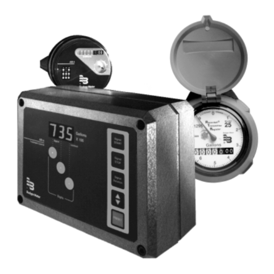
Model AR/e – AR/t
& RTR
BadgerMeter,Inc.
®
Water Treatment Control System
IMPORTANT !!!! Read this manual before
attempting any installation, wiring or operation.
Service Information (File manual for future reference and service.)
Serial Number
Service Line
Installation &
Operation Manual
Date Installed
/
Operator
/
IOM-034-12
Part No. 53400-034
7-01
Advertisement
Table of Contents
Troubleshooting

Related Manuals for Badger Meter AR/e


Summary of Contents for Badger Meter AR/e
- Page 1 Installation & Model AR/e – AR/t Water Treatment Control System & RTR Operation Manual IMPORTANT !!!! Read this manual before attempting any installation, wiring or operation. Service Information (File manual for future reference and service.) Serial Number Date Installed Service Line...
- Page 2 This manual contains information concerning the installation, To avoid damage in transit, Badger prod- operation and maintenance of the AR/e with AR/t or RTR Water ucts are shipped to the customer in spe- Conditioning Control System. To ensure proper performance cial shipping containers.
- Page 3 INSTALL BATTERY ON CIRCUIT BOARD ONLY AFTER WIRING IS COMPLETED. POWER INPUT The AR/e is designed to work with a 110 VAC power supply. In case of power failure, the unit will retain all programmed values and continue to count down (without display or output) for several hours.
- Page 4 PULSE INPUT (AR/t) In the Automatic mode, the relay will be energized at the end The AR/t transmitter sends pulse signals to the AR/e controller. of the batch for the amount of seconds programmed via the Each pulse represents a specific quantity of water for a SIGNAL DURATION procedure (see page 6).
- Page 5 GENERAL PROGRAMMING PROCEDURE In addition to the LED display and the digit keys, the front panel of the AR/e controller has two command keys (START and STOP) and three program keys (PRESET, SIGNAL DURA- TION and UP-DOWN COUNT).
- Page 6 TROUBLESHOOTING Most problems encountered when applying the AR/e control are due to wiring errors, improperly set functions or faulty transmitter connections. This section provides guidelines for the detection and correction of these and other problems. However, should the problem persist, contact our nearest representative or the factory for further assistance.
- Page 7 2. Unit is defective. 2. Replace unit. Test procedure does not work. 1. Unit is defective. 1. Replace unit. Memory does not function 1. Battery is defective. 1. Replace battery. during power outage. AR/e Circuit Board...
- Page 8 P.O. Box 245036, Milwaukee, WI 53224-9536 Telephone: (414) 355-0400 / (877) 243-1010 Fax: (414) 355-7499 / (866) 613-9305 ® www.badgermeter.com Copyright © Badger Meter, Inc. 2001. All rights reserved, all data subject to change without notice.
Need help?
Do you have a question about the AR/e and is the answer not in the manual?
Questions and answers