
Related Manuals for Aaeon AEC-6821

Summary of Contents for Aaeon AEC-6821
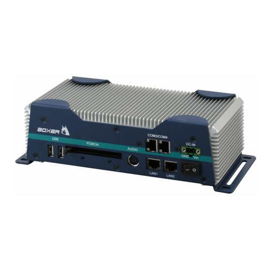
- Page 1 E m b e d d e d C o n t r o l l e r A E C - 6 8 2 1 AEC-6821 Fanless Embedded Controller AMD Geode LX800 Processor Dual 10/100Base-TX Ethernet 4 COM/ Audio/ 4 USB AEC-6821 Manual 1st Ed. October 2009...
- Page 2 AAEON assumes no liabilities resulting from errors or omissions in this document, or from the use of the information contained herein. AAEON reserves the right to make changes in the product design without notice to its users.
- Page 3 E m b e d d e d C o n t r o l l e r A E C - 6 8 2 1 Acknowledgments • Award is a trademark of Award Software International, Inc. • ™ CompactFlash is a trademark of the Compact Flash Association.
- Page 4 A E C - 6 8 2 1 Packing List Before you begin operating your PC, please make sure that the following materials have been shipped: AEC-6821 Embedded Controller Keyboard & mouse cable Phoenix Power Connector Wallmount Brackets RJ-45 to DB-9 Cables...
- Page 5 E m b e d d e d C o n t r o l l e r A E C - 6 8 2 1 Safety & Warranty 1. Read these safety instructions carefully. 2. Keep this user's manual for later reference. 3.
- Page 6 E m b e d d e d C o n t r o l l e r A E C - 6 8 2 1 The equipment does not work well, or you cannot get it to work according to the user’s manual. The equipment has been dropped and damaged.
- Page 7 E m b e d d e d C o n t r o l l e r A E C - 6 8 2 1 Below Table for China RoHS Requirements 产品中有毒有害物质或元素名称及含量 AAEON Boxer/ Industrial System 有毒有害物质或元素 部件名称 铅...
-
Page 8: Table Of Contents
2.4 Wallmount Installation ..........2-11 2.5 DIN Rail Installation........... 2-12 2.6 CompactFlash Card Installation (Version B)..... 2-13 2.7 Jumper Setting of AEC-6821 ........2-14 Chapter 3 Award BIOS Setup 3.1 System Test and Initialization........3-2 3.2 Award BIOS Setup ............ 3-3 Chapter 4 Driver Installation 4.1 Software Drivers............ - Page 9 4.7 Ethernet Software Configuration ....... 4-7 4.8 Installing LAN 82551er Driver ........4-8 4.9 Installing Audio Driver ..........4-9 4.10 Installing RAID Driver (for AEC-6821 Rev.A only) .. 4-10 Appendix A Programming The Watchdog Timer A.1 Programming for AEC-6821 Rev.A......A-2 A.2 ITE8712 Watchdog Timer Initial Program....A-6...
-
Page 10: Chapter 1 General Information
E m b e d d e d C o n t r o l l e r A E C - 6 8 2 1 Chapter General Information 1- 1 Chapter 1 General Information... -
Page 11: Introduction
AEC-6821 to be installed in a rugged transportation environment despite high ambient vibration. In addition to the fanless CPU, the AEC-6821 was use the AMD LX800 500MHz CPU, features one PCMCIA expansion slots for devices expansion. A DC power supply is commonly used in most vehicles and factory equipments. -
Page 12: Features
E m b e d d e d C o n t r o l l e r A E C - 6 8 2 1 1.2 Features • Fanless Design with AMD Geode LX800 500MHz Processor • 1 PCMCIA Slot for Expansion •... -
Page 13: Specifications
E m b e d d e d C o n t r o l l e r A E C - 6 8 2 1 1.3 Specifications System • CPU: AMD Geode LX800 500MHz • Memory: DDR SDRAM SODIMM x 1, Max. -
Page 14: Dimension
E m b e d d e d C o n t r o l l e r A E C - 6 8 2 1 (Optional) • System Control: Power on / off switch x 1;Reset button x 1 •... - Page 15 E m b e d d e d C o n t r o l l e r A E C - 6 8 2 1 Front Side Rear Side Rev. A Rev. B Chapter 1 General Information...
- Page 16 E m b e d d e d C o n t r o l l e r A E C - 6 8 2 1 Chapter Hardware Installation Chapter 2 Hardware Installation...
- Page 17 E m b e d d e d C o n t r o l l e r A E C - 6 8 2 1 2.1 Dimension Units: mm 2 - 2 Chapter 2 Hardware Installation...
-
Page 18: Hdd Module Installation
E m b e d d e d C o n t r o l l e r A E C - 6 8 2 1 2.2 HDD Module Installation Step 1: Open the HDD cover by loosening the screws on the bottom of the chassis. - Page 19 E m b e d d e d C o n t r o l l e r A E C - 6 8 2 1 Step 2: Open the bottom cover of the AEC-6821 and loosening the four screws...
- Page 20 E m b e d d e d C o n t r o l l e r A E C - 6 8 2 1 Step 4: Loosening the front panel of AEC-6821 Step 5: Connect IDE or SATA cable and SATA power...
- Page 21 E m b e d d e d C o n t r o l l e r A E C - 6 8 2 1 Connect the SATA cable and SATA power Step 6: Insert the Cable to the bottom of the chassis as the illustration below.
- Page 22 E m b e d d e d C o n t r o l l e r A E C - 6 8 2 1 SATA and Power Cables Step 7: Connect the IDE/ SATA and power cables to the Hard Disk Drive kit 2 - 7 Chapter 2 Hardware Installation...
- Page 23 E m b e d d e d C o n t r o l l e r A E C - 6 8 2 1 2 - 8 Chapter 2 Hardware Installation...
-
Page 24: Built-In Hdd Module Installation
A E C - 6 8 2 1 2.3 Built-in HDD Module Installation Step 1: Get the built-in HDD kit ready Step 2: Fasten the four screws with the bottom cover of AEC-6821 2 - 9 Chapter 2 Hardware Installation... - Page 25 E m b e d d e d C o n t r o l l e r A E C - 6 8 2 1 Step 3: Connect the IDE cable of AEC-6821 to the HDD kit 2 - 10...
-
Page 26: Wallmount Installation
E m b e d d e d C o n t r o l l e r A E C - 6 8 2 1 2.4 Wallmount Installation Fasten the brackets by screws. Bracket 2 - 11 Chapter 2 Hardware Installation... -
Page 27: Din Rail Installation
E m b e d d e d C o n t r o l l e r A E C - 6 8 2 1 2.5 DIN Rail Installation Step 1: Fix the DIN Rail kit with the screws on the chassis as the illustration shown. -
Page 28: Chapter 3 Award Bios Setup
E m b e d d e d C o n t r o l l e r A E C - 6 8 2 1 Chapter Award BIOS Setup Chapter 3 Award BIOS Setup 3-1... - Page 29 3. The CMOS memory has lost power and the configuration information has been erased. The AEC-6821 CMOS memory has an integral lithium battery backup for data retention. However, you will need to replace the complete unit when it finally runs down.
- Page 30 E m b e d d e d C o n t r o l l e r A E C - 6 8 2 1 3.2 Award BIOS Setup Awards BIOS ROM has a built-in Setup program that allows users to modify the basic system configuration.
- Page 31 Save CMOS value changes to CMOS and exit setup. Exit Without Saving Abandon all CMOS value changes and exit setup. You can refer to the "AAEON BIOS Item Description.pdf" file in the CD for the meaning of each setting in this chapter. Chapter 3 Award BIOS Setup 3-4...
-
Page 32: Chapter 4 Driver Installation
E m b e d d e d C o n t r o l l e r A E C - 6 8 2 1 Chapter Driver Installation Chapter 4 Driver Installation... -
Page 33: Software Drivers
E m b e d d e d C o n t r o l l e r A E C - 6 8 2 1 4.1 Software Drivers This chapter describes the operation and installation of the display drivers supplied on the Supporting CD-ROM that are shipped with your product. -
Page 34: Necessary To Know
E m b e d d e d C o n t r o l l e r A E C - 6 8 2 1 4.2 Necessary to Know The instructions in this manual assume that you understand elementary concepts of MS-DOS and the IBM Personal Computer. Before you attempt to install any driver from the Supporting CD-ROM, you should: Know how to copy files from a CD-ROM to a directory on the... -
Page 35: Installing Vga Driver
E m b e d d e d C o n t r o l l e r A E C - 6 8 2 1 4.3 Installing VGA Driver Win XP / Win XPe VGA Place the Driver CD-ROM into your CD-ROM drive and follow the steps below to install. -
Page 36: Installing Aes Driver
E m b e d d e d C o n t r o l l e r A E C - 6 8 2 1 4.4 Installing AES Driver Win XP / Win XPe AES Place the Driver CD-ROM into your CD-ROM drive and follow the steps below to install. -
Page 37: Installing Pci To Isa Bridge Driver
E m b e d d e d C o n t r o l l e r A E C - 6 8 2 1 4.5 Installing PCI to ISA Bridge Driver Win XP / Win XPe System Place the Driver CD-ROM into your CD-ROM drive and follow the following steps to install. -
Page 38: Installing Ethernet Driver
E m b e d d e d C o n t r o l l e r A E C - 6 8 2 1 4.6 Installing Ethernet Driver 1. Click on the Step 4 –lan folder 2. Double click on the Setup file located in the folder 3. -
Page 39: Installing Lan 82551Er Driver
E m b e d d e d C o n t r o l l e r A E C - 6 8 2 1 After you have made your selections and the configuration is what you want, press <ESC>. A prompt will appear asking if you want to save the configuration. -
Page 40: Installing Audio Driver
E m b e d d e d C o n t r o l l e r A E C - 6 8 2 1 9. Click on Next 10. Select Search for a suitable driver..., then click on Next 11. -
Page 41: Installing Raid Driver (For Aec-6821 Rev.a Only)
VT6421 and treat it as a third-part driver. Please follow below steps to install the driver with Operating System. 1. Creating a Drive Disk: copy the SATA driver from AAEON CD to floppy disk before install OS. Click on Step 7-VIA_RAID_V580C... - Page 42 E m b e d d e d C o n t r o l l e r A E C - 6 8 2 1 Click on DriverDiskPrep.exe (see below picture) 4-11 Chapter 4 Driver Installation...
- Page 43 E m b e d d e d C o n t r o l l e r A E C - 6 8 2 1 Click on the OS what you are going to install. Install Floppy or USB Floppy 4-12 Chapter 4 Driver Installation...
- Page 44 E m b e d d e d C o n t r o l l e r A E C - 6 8 2 1 Finish: driver disk ready. 2. Following are the raid configuration steps. Press <Tab> key to enter Raid BIOS setup (Raid BIOS only enable when SATA HDD connected) 4-13 Chapter 4 Driver Installation...
- Page 45 E m b e d d e d C o n t r o l l e r A E C - 6 8 2 1 Create Array 4-14 Chapter 4 Driver Installation...
- Page 46 E m b e d d e d C o n t r o l l e r A E C - 6 8 2 1 After Raid has been created, set this array bootable. 4-15 Chapter 4 Driver Installation...
- Page 47 E m b e d d e d C o n t r o l l e r A E C - 6 8 2 1 4-16 Chapter 4 Driver Installation...
- Page 48 E m b e d d e d C o n t r o l l e r A E C - 6 8 2 1 Now the Raid Array is ready for OS installation 3. Insert your Windows CD, and then restart the computer 4.
- Page 49 E m b e d d e d C o n t r o l l e r A E C - 6 8 2 1 Note: When F6 is active, a prompt appears at the bottom of the screen for only 5 seconds. If you miss your chance to press F6, restart your computer.
- Page 50 E m b e d d e d C o n t r o l l e r A E C - 6 8 2 1 8. The computer reads the disk 9. When the SATA driver is found, press Enter. 4-19 Chapter 4 Driver Installation...
- Page 51 E m b e d d e d C o n t r o l l e r A E C - 6 8 2 1 10. Follow the on-screen instructions to complete the installation. After finish installing OS, you have to install VIA Raid management Utility.
- Page 52 E m b e d d e d C o n t r o l l e r A E C - 6 8 2 1 4-21 Chapter 4 Driver Installation...
-
Page 53: Appendix A Programming The Watchdog Timer
E m b e d d e d C o n t r o l l e r A E C - 6 8 2 1 Appendix Programming the Watchdog Timer Appendix A Programming the Watchdog Timer... -
Page 54: Programming For Aec-6821 Rev.a
E m b e d d e d C o n t r o l l e r A E C - 6 8 2 1 A.1 Programming for AEC-6821 Rev.A AEC-6821 Rev.A utilizes ITE 8712 chipset as its watchdog timer controller. Below are the procedures to complete its configuration and the AAEON intial watchdog timer program is also attached based on which you can develop customized program to fit your application. - Page 55 E m b e d d e d C o n t r o l l e r A E C - 6 8 2 1 There are three steps to complete the configuration setup: (1) Enter the MB PnP Mode; (2) Modify the data of configuration registers; (3) Exit the MB PnP Mode.
- Page 56 E m b e d d e d C o n t r o l l e r A E C - 6 8 2 1 WatchDog Timer Configuration Registers Configure Control (Index=02h) This register is write only. Its values are not sticky; that is to say, a hardware reset will automatically clear the bits, and does not require the software to clear them.
- Page 57 E m b e d d e d C o n t r o l l e r A E C - 6 8 2 1 WatchDog Timer Configuration Register (Index=72h, Default=00h) WatchDog Timer Time-out Value Register (Index=73h, Default=00h) Appendix A Programming the Watchdog Timer A-5...
-
Page 58: Ite8712 Watchdog Timer Initial Program
E m b e d d e d C o n t r o l l e r A E C - 6 8 2 1 A.2 ITE8712 Watchdog Timer Initial Program .MODEL SMALL .CODE Main: CALL Enter_Configuration_mode CALL Check_Chip mov cl, 7 call Set_Logic_Device ;time setting... - Page 59 E m b e d d e d C o n t r o l l e r A E C - 6 8 2 1 ; game port enable mov cl, 9 call Set_Logic_Device Initial_OK: CALL Exit_Configuration_mode MOV AH,4Ch INT 21h Enter_Configuration_Mode PROC NEAR MOV SI,WORD PTR CS:[Offset Cfg_Port]...
- Page 60 E m b e d d e d C o n t r o l l e r A E C - 6 8 2 1 Exit_Configuration_Mode ENDP Check_Chip PROC NEAR MOV AL,20h CALL Read_Configuration_Data CMP AL,87h JNE Not_Initial MOV AL,21h CALL Read_Configuration_Data CMP AL,12h JNE Not_Initial...
- Page 61 E m b e d d e d C o n t r o l l e r A E C - 6 8 2 1 MOV DX,WORD PTR CS:[Cfg_Port+06h] IN AL,DX Read_Configuration_Data ENDP Write_Configuration_Data PROC NEAR MOV DX,WORD PTR CS:[Cfg_Port+04h] OUT DX,AL XCHG AL,AH MOV DX,WORD PTR CS:[Cfg_Port+06h]...
- Page 62 E m b e d d e d C o n t r o l l e r A E C - 6 8 2 1 push ax push cx xchg al,cl mov cl,07h call Superio_Set_Reg pop cx pop ax Set_Logic_Device endp ;Select 02Eh->Index Port, 02Fh->Data Port Cfg_Port DB 087h,001h,055h,055h...
-
Page 63: Programming For Aec-6821 Rev.b
AEC-6821 Rev.B utilizes W83627EHG chipset as its watchdog timer controller. Below are the procedures to complete its configuration and the AAEON intial watchdog timer program is also attached based on which you can develop customized program to fit your application. Configuring Sequence Description... - Page 64 E m b e d d e d C o n t r o l l e r A E C - 6 8 2 1 (3) Exit the W83627EHG config Mode. Undesired result may occur if the config Mode is not exited normally. (1) Enter the W83627EHG config Mode To enter the W83627EHG config Mode, two special I/O write operations are to be performed during Wait for Key state.
- Page 65 E m b e d d e d C o n t r o l l e r A E C - 6 8 2 1 = 10 Power LED pin is a 1Hz toggle pulse with 50 duty cycle. = 11 Power LED pin is a 1/4Hz toggle pulse with 50 duty cycle.
- Page 66 E m b e d d e d C o n t r o l l e r A E C - 6 8 2 1 WatchDog Timer Register III (Index=F7h, Default=00h) Bit 7 : Mouse interrupt reset Enable or Disable Watchdog Timer is reset upon a Mouse interrupt Watchdog Timer is not affected by...
-
Page 67: W83627Ehg Watchdog Timer Initial Program
E m b e d d e d C o n t r o l l e r A E C - 6 8 2 1 A.4 W83627EHG Watchdog Timer Initial Program Example: Setting 10 sec. as Watchdog timeout interval ;/////////////////////////////////////////////////////////////////////////////////////////////// Mov dx,2eh ;Enter W83627EHG config mode... - Page 68 E m b e d d e d C o n t r o l l e r A E C - 6 8 2 1 ;/////////////////////////////////////////////////////////////////////////////////////////////// Dec dx Mov al,0f5h ;CRF5 (PLED mode register) Out dx,al Inc dx In al,dx And al,not 08h ;Set second as counting unit Out dx,al...
-
Page 69: Appendix B I/O Information
E m b e d d e d C o n t r o l l e r A E C - 6 8 2 1 Appendix I/O Information B - 1 Appendix B I/O Information... -
Page 70: I/O Address Map
E m b e d d e d C o n t r o l l e r A E C - 6 8 2 1 B.1 I/O Address Map AEC-6821 Rev.A B - 2 Appendix B I/O Information... - Page 71 E m b e d d e d C o n t r o l l e r A E C - 6 8 2 1 AEC-6821 Rev.B B - 3 Appendix B I/O Information...
-
Page 72: St Mb Memory Address Map
E m b e d d e d C o n t r o l l e r A E C - 6 8 2 1 B.2 1 MB Memory Address Map AEC-6821 Rev.A B - 4 Appendix B I/O Information... - Page 73 E m b e d d e d C o n t r o l l e r A E C - 6 8 2 1 AEC-6821 Rev.B B - 5 Appendix B I/O Information...
-
Page 74: Irq Mapping Chart
E m b e d d e d C o n t r o l l e r A E C - 6 8 2 1 B.3 IRQ Mapping Chart AEC-6821 Rev.A AEC-6821 Rev.B B - 6 Appendix B I/O Information... -
Page 75: Dma Channel Assignments
E m b e d d e d C o n t r o l l e r A E C - 6 8 2 1 B.4 DMA Channel Assignments AEC-6821 Rev.A AEC-6821 Rev.B B - 7 Appendix B I/O Information...
Need help?
Do you have a question about the AEC-6821 and is the answer not in the manual?
Questions and answers