Entrematic EM PSL150 Installation And Service Manual
Hide thumbs
Also See for EM PSL150:
- Quick start (4 pages) ,
- User manual (22 pages) ,
- User manual (26 pages)

Related Manuals for Entrematic EM PSL150


Summary of Contents for Entrematic EM PSL150
- Page 1 Sliding Door Operator EM PSL150 Installation and Service Manual Original instructions 1016248-EMEI-2.0 Issue 2017-03-13...
- Page 2 © All rights in and to this material are the sole property of Entrematic Nordic AB. Copying, scanning, alterations or modifications are expressly forbidden without the prior written consent of Entrematic Nordic AB. Rights reserved for changes without prior notice.
-
Page 3: Table Of Contents
Hanging and mounting the door leaves ..........................11.9 Height adjustment ..................................11.10 Installation of Entrematic Nordic floor guides (frame doors by others) ..............11.11 Depth adjustment of the door leaves ............................. 11.12 Installation of components and electrical wiring ....................... 11.13 Installation of tension wheel assembly .......................... - Page 4 12.2.2 Drive unit (HDD/DD) ..............................12.2.3 Main control unit (MCU/MCU-ER) .......................... 12.2.4 Additional electronic units can be connected for extra functionality ............12.2.4.1 Battery unit 12 V (EEU 12) ........................12.2.4.2 Battery unit 24 V (EEU 24) ........................12.2.4.3 I/O unit (IOU) ............................. 12.2.5 Connection of electrical units ..........................
-
Page 5: Revision
1 Revision Revision Following pages have been revised: Page Revision 1.0 → 2.0 Added warning about brands. Added parameters MCU 5F, MCU 4A, and MCU 3A. Changed parameters IOU 99 and MCU 70. Added parameters OMS b7, OMS b8, OMS C7, and OMS C8. Changed parameters OMS b0 and OMS C0. -
Page 6: Instructions For Safe Operation
2 Instructions for safe operation Instructions for safe operation • Failure to observe the information in this manual may result in personal injury or damage to equipment. • To reduce the risk of injury of persons - use this operator only with pedestrian doors. -
Page 7: Important Information
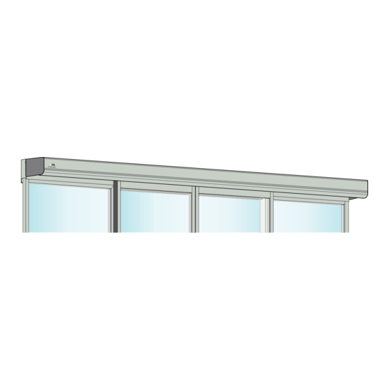
The EM PSL150 is designed to be surface-mounted to the wall or a beam. It is easy to install for both new construction and retrofit application, and it can be adapted to a wide range of door require- ments. -
Page 8: Electronic Equipment Reception Interference
Environmental requirements Entrematic Nordic products are equipped with electronics and may also be equipped with batteries containing materials which are hazardous to the environment. Disconnect power before removing electronics and battery and make sure it is disposed of properly according to local regulations (how and where) as was done with the packaging material. -
Page 9: About This Manual
4 About this manual About this manual This manual describes functions of the EM PSL150 Sliding Door Operator and for software release 3.2. Software releases with included software versions Release Versions SW 3.0 7.4.9.2 8.4.9.2 1.1.9.2 3.5.9.2 4.2.9.2 SW 3.1 8.4.12.2... -
Page 10: Technical Specification
For low energy movement: 150 kg/leaf Clear opening: Bi-parting: EM PSL150-2: 1000 3000 mm Single Slide: EM PSL150-R/L: 800 3000 mm Opening and closing Variable up to approx. (EM PSL150-2): speed: High performance 1.4 m/s Exceptional performance 1.7 m/s Hold open time:... -
Page 11: Door Weight In Relation To Performance Level
5 Technical specification Door weight in relation to performance level Plastic wheels Main control Sealing type Door weight [kg] Performance level Single Bi-parting Escape Normal seal 1 x 90 2 x 90 Tight seal 1 x 75 2 x 75 High performance Non-escape Normal seal... -
Page 12: Classification To Din 18650-1
5 Technical specification Classification to DIN 18650-1 Classification to DIN 18650-1 Digit 1 Digit 2 Digit 3 Digit 4 Digit 5 Digit 6 Digit 7 Digit 8 1,2,3 1,2,4 Type of drive, digit 1. sliding door drive Drive durability, digit 2. 1 000 000 test cycles, at 4 000 cycles/day Type of door leaf, digit 3. -
Page 13: Design And Function Description
Emergency escape The EM PSL150 can be combined with an emergency unit that automatically opens or closes the doors in the event of a power failure and can also be interfaced with the fire alarm or smoke detector. -
Page 14: Models
Models Two main models are available: • EM PSL150 2; for bi-parting doors, consisting of a pair of door leaves which are sliding away from each other to form a common door opening. • EM PSL150 1; for single sliding doors with one right or left opening door leaf. -
Page 15: Part Identification
8 Part identification Part identification 9 10 Description Description Mains connection Tooth belt Power supply unit (PSU 75/PSU 150) Tension wheel Drive unit (HDD/DD) Door stop Main control unit (MCU/MCU-ER) Cover I/O Unit (IOU) Operation mode selector (OMS) Battery (EEU 12/EEU 24) Support beam Door carriage Lock... -
Page 16: Space Required
9 Space required Space required Frame doors by others EM Slim System COH = Clear opening height DH = Door height (incl. door adapter) FFL = Finished floor level Max. 260 Max. 111 Issue 2017-03-13 1016248-EMEI-2.0... -
Page 17: Pre-Installation
10 Pre-installation Pre-installation 10.1 General tips/Safety concerns In all instances, where work is being done, the area is to be secured from ped- estrian traffic, and the power removed to prevent injury. • If there are sharp edges after drilling the cable outlets, chamfer the edges to avoid damage to the cables. -
Page 18: Mechanical Installation
Check that the fixing material and the upper part of the door leaf have the necessary reinforcements and that the floor is level and smooth. The beam/wall used to fix the support beam must be flat and smooth. If necessary use Entrematic Nordic mounting spacers behind the support beam to keep its straightness. -
Page 19: Installation Examples To Consider During Installation
11 Mechanical installation 11.2 Installation examples to consider during installation Note! See the local building regulations for each country, with regards to the permissible minimum opening width, that shall be followed. Recommended installation (EM PS) To reduce the risk for shearing of finger the jamb is used as door stop for closing and labyrinth sealings are used between door leaf (1) and fixed screen (2). - Page 20 11 Mechanical installation The safety distances measured between the secondary closing edge (4) and surrounding fixed parts (5) are shown in the illustrations below. If the distance between the door and wall/side light is 100 mm or less, there shall be at least 200 mm between the door and a opposing surface when the door is in full open position.
-
Page 21: Installing/Removing The Cover, Standard Cover Lock
11 Mechanical installation 11.3 Installing/removing the cover, standard cover lock Open cover Secure and unsecure cover Secure and unsecure the open cover as shown below. Figure 1: Old detachment guard Figure 2: New detachment guard 1016248-EMEI-2.0 Issue 2017-03-13... - Page 22 11 Mechanical installation Close cover New cover latch In the illustrations above the old cover latch is used. The illustration below shows the new cover latch and how it is attached. Issue 2017-03-13 1016248-EMEI-2.0...
-
Page 23: Installing/Removing The Cover, Optional Cover Lock
11 Mechanical installation 11.4 Installing/removing the cover, optional cover lock Open cover 1016248-EMEI-2.0 Issue 2017-03-13... - Page 24 11 Mechanical installation Close cover Issue 2017-03-13 1016248-EMEI-2.0...
-
Page 25: Installing The Door Adapter On Top Of The Door Leaf (Frame Doors By Others)
11.5 Installing the door adapter on top of the door leaf (frame doors by others) For Entrematic Nordic doors the door adapters and door holders are factory-mounted, proceed to page 26. a If necessary cut the door adapter (1) to correspond with the door leaf width. -
Page 26: Installation Of Support Beam
11 Mechanical installation 11.6 Installation of support beam Marking and fixing Determine the installation height from the highest point of the finished floor: a Measure the door leaf height inclusive the door adapter. b Add 108 mm or 113 mm if break-out unit PSB with 8 mm surface mounted threshold/floor guide track is installed. - Page 27 11 Mechanical installation Bi-parting Single sliding 250 250 500 250 250 500 LAP+50 Installation height DH + 108 (or DH + 113 for PSB) ø7 SBL = Support beam length FFL = Finished floor level LAP = Overlap (profile width) Without threshold Threshold on floor Threshold in floor...
-
Page 28: Installing The Door Holders On The Door Adapter (Frame Doors By Others)
11 Mechanical installation 11.7 Installing the door holders on the door adapter (frame doors by others) a Remove the height adjustment fastening screw (1) and the height adjustment cam (2). Remove the wheel holder (4) from the door holder (3). Height adjustment fastening screw Height adjustment... - Page 29 11 Mechanical installation c Fasten the door holder (3a) at a distance A from the trailing edge of door leaf (6), see picture below. Bi-parting door: Fasten the door holder (3b) at a distance B from the estimated centre line between the doors.
- Page 30 11 Mechanical installation Part identification door carrier Height adjustment fastening screw Carriage wheel Height adjustment cam Anti-riser device Door holder • left illustration, Engaged Depth adjustment • right illustration, Disengaged Door holder fastening screw Secondary bogie 2-Wheel holder Clips, single wheel 2-Wheel holder, short Clips, bogie wheels 4-Wheel holder...
-
Page 31: Hanging And Mounting The Door Leaves
11 Mechanical installation 11.8 Hanging and mounting the door leaves a Loosen and remove the height adjustment fastening screw (1) and the height adjustment cam (2) from the wheel holders (5) that are already installed in the support beam. The anti-riser devices shall be engaged when the wheels are placed in the beam (4), see page 30. -
Page 32: Height Adjustment
11 Mechanical installation 11.9 Height adjustment The door can be height adjusted +/- 8 mm by turning the height adjustment cam (2). a Indication on the cam show what height the door is adjusted to (in mm). Note! The illustration below shows a zero adjusted cam. b Check that the door(s) is hanging horizontally. -
Page 33: Installation Of Entrematic Nordic Floor Guides (Frame Doors By Others)
11 Mechanical installation 11.10 Installation of Entrematic Nordic floor guides (frame doors by others) The floor guides can be adjusted depthwise about ± 4 mm after being installed, using the eccentric nut underneath the plastic block. Note! Before installing the floor guide make sure that the plastic block is adjusted to the middle position to ensure full adjustability (±4 mm). -
Page 34: Depth Adjustment Of The Door Leaves
11 Mechanical installation 11.11 Depth adjustment of the door leaves a The distance A, between the top of the door leaf and the fixed screen, is to be adjusted by loosening the two screws connecting the door holder (1) to the door adapter (2). b The holes in the door holder (1) are slotted and the door leaf/adapter (2) can be adjusted ±7 c The distance A shall be 22 mm for third party doors and 20 mm for EM Slim System. -
Page 35: Installation Of Components And Electrical Wiring
11 Mechanical installation 11.12 Installation of components and electrical wiring a Start from the left side of the operator, loosen and slide the mains connection and the power supply sideways to obtain 65 mm from the left side of the support beam to the left side of the power supply. - Page 36 11 Mechanical installation c Install the drive unit with its outgoing shaft 350 mm from the left side of the support beam. Tighten the screws (5) with a force of 10 Nm. Start with the right screw and ensure that the drive unit is fixed in the beam. Continue with the left screw and visually ensure that this screw also is securely tightened in the beam.
-
Page 37: Installation Of Tension Wheel Assembly
11 Mechanical installation 11.13 Installation of tension wheel assembly a Tighten the nuts (1) on the belt tension by hand. No space between the nut (1), plastic washer (2), screw (3) and the tension frame (4). Top view Plastic washer Screw Tension frame b Starting position of the adjustment screw (6). -
Page 38: Placement Of The Transmission Bracket
11 Mechanical installation 11.14 Placement of the transmission bracket For bi-parting and single left opening doors The upper transmission bracket shall be attached to the carriage wheel holder on the leading edge of the right door. The lower transmission bracket shall be attached to the carriage wheel holder on the leading edge of the left door. -
Page 39: Attachment Of Tooth Belt Fitting
11 Mechanical installation 11.15 Attachment of tooth belt fitting a The tooth belt (1) is delivered separately and is pre-cut to the right length. Route the belt (1) around the drive unit pulley (2) and around the tension wheel (3). b For bi-parting and single right opening doors the belt ends are joined with the belt clamp (4) in the upper part of the belt. -
Page 40: Checking And Adjusting The Belt Tension
11 Mechanical installation 11.16 Checking and adjusting the belt tension If the belt tension has to be corrected, proceed as follows: a Remove the slack reducer, if fitted. b Loosen the fixing screw (1) in the middle of the tension wheel (5) without removing it. c Screw the adjustment screw (2) to its outmost position. -
Page 41: Bi-Parting Operators
11 Mechanical installation 11.17 Bi-parting operators a Put doors in fully closed position. Make sure that the doors trailing edge is align with the side light. b Put the belt clamp (4) centered over the lower transmission bracket (5). c When centered snap the belt clamp (4) in place. d Check door panels for proper centering in the fully closed and opened positions. -
Page 42: Adjustment Of The Door Stop
11 Mechanical installation 11.18 Adjustment of the door stop a Push the doors by hand to the desired opening. b For third party doors the door leaf can be fully open. For single doors, shearing of finger is reduced by using a jamb as a door stop in closed position. Labyrinth sealing is used between the trailing edge on the door leaf and the fixed side screen to prevent a finger trap. -
Page 43: Route The Cables And Attach The Plastic Cable Holders, See Illustrations Below
11 Mechanical installation 11.19 Route the cables and attach the plastic cable holders, see illustrations below Cable holder 1016248-EMEI-2.0 Issue 2017-03-13... -
Page 44: Attachment Of Slack Reducer
11 Mechanical installation 11.20 Attachment of slack reducer Attach the slack reducer between the eighth and ninth belt tooth on each side of the low transmis- sion bracket. If two slack reducers are needed put the second slack reducer in the same way under the upper transmissions bracket. -
Page 45: Attachment Of Product Label
11 Mechanical installation 11.21 Attachment of product label When properly installed and adjusted, attach the local product label on the right side of the lower part of the operator cover. XXXXXXXXXX XX XXXXXXXXX XXXXXXX Service XXX XXX XXX ID No. Year 1016248-EMEI-2.0 Issue 2017-03-13... -
Page 46: Electrical Connections
12 Electrical connections Electrical connections Note! During any work with the electrical connections the mains power and the electrical emer- gency unit must be disconnected. • Place the electric switch easily accessible from the operator. If a plug contact is used in the in- stallation the wall socket shall be placed easily accessible from the operator. -
Page 47: Electrical Units
12 Electrical connections The mains connection (5) must remain isolated until the wiring is completed. Then connect to the supply unit (6). Connection cable Power supply unit 12.2 Electrical units 12.2.1 Power supply unit (PSU 75/PSU 150) Two different main power supplies are available, 75 W and 150 W. PSU 75 PSU 150 (Marked with yellow label) -
Page 48: Main Control Unit (Mcu/Mcu-Er)
12 Electrical connections 12.2.3 Main control unit (MCU/MCU-ER) The main control unit has the connection for the power supply, drive unit, operation mode selector, activation units, electromechanical lock and batteries. An installer interface with a two digit display and four push buttons is used for function selection, adjustments and for troubleshooting. See page 57 for details. -
Page 49: Additional Electronic Units Can Be Connected For Extra Functionality
12 Electrical connections 12.2.4 Additional electronic units can be connected for extra functionality Battery unit 12 V (EEU 12) For emergency opening or for fire closing a 12 V battery can be connected that automatically opens or closes the door in the event of a power failure. For higher speed, the 24 V battery below is recom- mended and is also a demand to conform with authority demands for escape routes. -
Page 50: I/O Unit (Iou)
12 Electrical connections I/O unit (IOU) The IOU has two labels, a Hardware label (3) and a Software label (4). The hardware label states revision of the IOU and applies to PCB or hardware changes. The software label states the software version. Note! Newer IOU's will not have the software version stated. -
Page 51: Connection Of Electrical Units
12 Electrical connections 12.2.5 Connection of electrical units 1016248-EMEI-2.0 Issue 2017-03-13... - Page 52 Battery wake up Sustainable drive mode OFF Emergency open Open/Close impulse/Interlock OFF 12 Electrical connections Nurse impulse/LDE down Close impulse/LDE up MCU/MCU-ER Lock delay LD belt lock only Lock delay LD belt lock only Lock Lock (+) Lock (+) Lock (+) 24 V DC (+) 24 V DC Inner impulse...
-
Page 53: Connection Of Activation And Safety Units
12 Electrical connections 12.3 Connection of activation and safety units See sensor manuals for mounting and adjustments. Protective device shall comply with EN 12978. * EMSC32-M * EMSC53-M EMSA11 EMSA51 *EMSC31-E *EMSC53-E EMSA12 *EMSC31-M 0 1 C 1 2 3 4 5 NO NC A I G F B E C H A F G J C E B H... -
Page 54: Connection Of Presence Activation Units
12 Electrical connections 12.4 Connection of presence activation units * SBK-111 * EMSP56-M * EMSP32-M EMSP31 NPN/R (NO) NPN/N (NC) Blue sleeve Blue sleeve Red sleeve sleeve A B C A A B C A B C D C I G B I G F B E C H 8 8 14 8 8 8 13... -
Page 55: Connection Of Accessories
12 Electrical connections 12.5 Connection of accessories Emergency Lock Lock Secondary inner impulse monitoring Fire impulse opening Repeated fire closing New version (fireman’s EMSC31-E EMSC53-E opening) Old version [non-locking Current output button] Relay output E J A B C F N G I A F J B A G C D E F J H M B A C G D I E F... -
Page 56: Start-Up
13 Start-Up Start-Up Start-up and adjustment must be carried out in the following order when the operator is installed. a Connect the mains plug to the control unit. b Push and hold the learn button for 2 seconds before making any connection into the terminals. Release the learn button when there is a flashing "L"... -
Page 57: Adjustments And Selection Of Special Operating Functions
13 Start-Up 13.1 Adjustments and selection of special operating functions The main control unit has a two-digit display that shows text and/or digits. On the right side of the display are four push buttons. The display can show 4 different modes: a Parameter mode. - Page 58 13 Start-Up E1 = flashing letter E followed by a digit displays an active error (1-9). The digit shows the main type of error. The display switches between this main error and a two digit number to specify the error. If several errors are active they are displayed in a sequence.
-
Page 59: The Learn Function Can Be One Of Three Different Types
13 Start-Up 13.2 The Learn function can be one of three different types 1 Push and hold the Learn/Exit button for more than one and less than two seconds, then each connected electronic module is recognized. 2 Push and hold the Learn/Exit button for more than two seconds and the display flashes L. A complete Learn cycle will start after 2 seconds when the Learn/Exit button is released. -
Page 60: Display Test And Configuring Of Parameters
13 Start-Up 13.3 Display test and configuring of parameters a When the display shows "on", push the Select button and each of the two display windows make a rotating test pattern. b Verify that all seven segments of the two display windows are lit during the test. If not there is a risk of misjudgment of the digits shown in a defective display. -
Page 61: Status Indication On The Display
13 Start-Up 13.4 Status indication on the display Select status indication by setting parameter 5E = 01. The display shows the different impulses that are active. The status viewing starts with showing St as for Status, then one or many numbers representing the different active impulses in to the oper- ator. -
Page 62: Configuration Parameters (Sorted After Functionality)
13 Start-Up 13.5 Configuration parameters (sorted after functionality) Note! Some of the parameters below are not accessible, depending of different options installed. For further explanations of parameters below, see page 67. FUNCTION parameters Param. Description Range MCU 5B Robbery function. Off(00) / On(01) 00-01 MCU 5E Status indication. - Page 63 13 Start-Up DRIVE parameters Param. Description Range MCU 15 Run Program. Smooth(01) to Max Performance(05) 01-05 MCU 49 Opening Max Force 02-19 N x10 MCU 4A Close Kick Force 00-19 N x10 MCU 50 Closing Max Force 02-19 N x10 MCU 64 Power Supply Type.
- Page 64 13 Start-Up OPERATION MODE SELECTOR parameters Param. Description Range OMS B0 Operation Mode Selector Variant, OMS-1. 01-04 3 buttons with EXIT(01) / 3 buttons with AUTO(02) / 4 buttons(03) / 5 buttons(04) OMS B1 Operation Mode Selector Key Lock, OMS-1. Off(00) / Hold for two 00-02 sec(01) / Four pushes(02) OMS B2...
- Page 65 13 Start-Up ELECTROMECHANICAL LOCK parameters Param. Description Range MCU 05 Lock Configuration (main control). No lock(00) / LDP(01) / LD(02) / 00-05 LDP Low Energy(03) / LD Low Energy(04) / Not to be used(05) MCU 06 Lock Release. Off(00) / On(01) 00-01 MCU 42 Remain Locked at Stop.
- Page 66 13 Start-Up SPEED parameters Param. Description Range MCU 00 High Speed Opening 10-70 cm/sec MCU 01 Low Speed 05-70 cm/sec MCU 02 High Speed Closing 10-70 cm/sec POSITION parameters Param. Description Range MCU 5C Pharmacy open 1 position 00-99 cm MCU 5D Pharmacy open 2 position 00-99 cm...
-
Page 67: Description Of Parameters
13 Start-Up 13.6 Description of parameters Main control board parameters Parameter Name Value Description High Speed Opening Sets the maximum opening speed. Unit cm/s. Low Speed The low speed is self adjusting to optimal operation if this parameter is set to max. Depending on authority or installa- tion requirements the low speed, low speed distance opening and/or closing can be further reduced. - Page 68 13 Start-Up Main control board parameters Parameter Name Value Description Presence Impulse Monitoring Presence impulse monitoring is a demand to be activated according to EN 16005 or DIN 18650 if the door travels faster than adjusted according to PRA-0004. No monitoring of precense impulse Set to “00”...
- Page 69 13 Start-Up Main control board parameters Parameter Name Value Description Run Program 01-05 Performance adjustment. Sets how fast or slow the door shall accelerate or break. Smooth For light doors. Max Performance For heavy doors. Inner Impulse (motion) Monitoring 00-01 According to EN 16005 or DIN 18650 it is a demand to have Inner impulse monitoring = On in escape routes.
- Page 70 13 Start-Up Main control board parameters Parameter Name Value Description Presence Hold Open Time 00-60 Hold open time for Presence impulses 1 & 2. At least 2 sec to meet ANSI demand. Unit seconds. Side Presence Input 1 Configuration 00-01 Parity of side presence sensor.
- Page 71 13 Start-Up Main control board parameters Parameter Name Value Description Hold Force in EXIT and OFF Mode 00-01 With an electromechanical lock this hold force can be unne- Selection cessary. Toggle Operation Mode Selector 00-01 In operation mode selection OFF the mode must be changed after Stop before normal operation after a Stop impulse.
- Page 72 13 Start-Up Main control board parameters Parameter Name Value Description Battery Type 00-02 What type of battery that is mounted in the operator is identified during the Learn. No battery Remain Locked at Stop 00-01 The parameter sets how the lock shall act when Stop impulse is activated (for example break-out).
- Page 73 13 Start-Up Main control board parameters Parameter Name Value Description Push & Close 00-01 When this parameter is set to On (01) the motor will in oper- ation mode selections OFF or EXIT try to close the door with the force selected by parameter 50 “Closing Max Force”, if someone tries to open it manually.
- Page 74 13 Start-Up Main control board parameters Parameter Name Value Description Pharmacy open 1 position 00-99 Lock for pharmacy functionality is not yet available. The door will open the configured distance when a Pharmacy impulse 1 is given. The distance is calculated on one door leaf.
- Page 75 13 Start-Up Main control board parameters Parameter Name Value Description Power Supply Type 01-02 150 / 75 W power supply depending on desired performance and installed power supply. See also parameters 49 Opening Max Force, 50 Closing Max Force, and 71 Max Motor Power. 150W Sustainable Drive Mode 00-01...
- Page 76 13 Start-Up Main control board parameters Parameter Name Value Description Synchronizing Function 00-01 Interconnection cable needed. Interconnection of operators MCU-1 MCU-2 Maximum cable length 500 m. Length over 30 m, use a straight-through shielded twisted pair (STP/FTP) cable, see page 86. External Bus Device ID 01-99 In a chain of interconnected operators one of them has to...
- Page 77 13 Start-Up I/O Board parameters Parameter Name Value Description Function Select IOU-TB:3 00-03 No function Nurse function The door will open to partial opening in operation mode se- lections EXIT, AUTO and AUTO PARTIAL. LDE up Espagnolette lock. Sets input to LDE lock up. Interlock out When configuring for interlock also set parameter 6A = 01 Function Select IOU-TB:4...
- Page 78 13 Start-Up I/O Board parameters Parameter Name Value Description Lock Configuration 00-04 LDB = locked with power and bistable, LDE = espagnolette lock. No lock No lock Bi-stable lock LDB = locked with power and bistable Espagnolette lock LDE = espagnolette lock Function Select IOU-TB:6 Possibility to disable Sustainable drive mode or to disable Mode Selector with this function through I/O...
- Page 79 13 Start-Up Operation mode selector parameters Parameter Name Value Description Operation Mode Selector Variant, 01-04 Europe = 5 buttons (04). OMS-1 3 buttons with EXIT 3 buttons with AUTO 4 buttons 5 buttons Operation Mode Selector Key Lock, 00-02 Four pushes = OMS-1 Parameters configured automatically by the operator are locked when changed through the MMI.
- Page 80 13 Start-Up Operation mode selector parameters Parameter Name Value Description Choose Terminal mode of the oper- 00-02 ation mode selector, OMS-1 The buttons on OMS are disabled The OMS-1 adapts to system mode The OMS-1 is setting the operation mode Mode Selector, Self Service Indica- 00-01 Orange flashing service LED.
- Page 81 13 Start-Up Operation mode selector parameters Parameter Name Value Description Choose Priority of the operation 25-99 Selectable between 25 - 99 mode selector, OMS-2 The lower the number the higher the priority. Choose group of the operation 00-10 Selectable between 00 - 10 mode selector, OMS-2 This controls which MCU that looks at which OMS.
-
Page 82: Signage
European directives and equivalent national legislation outside the European Union. Product label: Mandatory Emergency break-out: Mandatory, if approved for escape route. Entrematic Nordic door sticker: Mandatory according to Entrematic Nordic brand instructions, European directives and equivalent national legislation outside the European Union, to highlight the presence of the glass. -
Page 83: Accessories
15 Accessories Accessories 15.1 Interconnection of operators 15.1.1 Interconnection cable Interconnection cable is used for controlling several operators with one or more operation mode selectors (OMS) and for interlocking or synchronization. Operators can communicate with each other by connecting an interconnection cable between the operators. -
Page 84: Hardware Configuration For Interconnection
15 Accessories MCU-1 MCU-2 15.1.2 Hardware configuration for interconnection When interconnecting more than two units (MCU and/or operation mode selectors (OMS)) to the external bus, only the two end units must be terminated. To make this, the jumper JMP shall be removed from the middle MCU(s). -
Page 85: Interlock
15 Accessories 15.2 Interlock When operators are interlocked only one door can open at the time. The open door must close before the other door can open. For instance from the start: both doors are closed. If door 1 gets an impulse this door opens. -
Page 86: Synchronization
15 Accessories a Follow the instructions in chapter 84 on page 15.1.3. MCU-1 MCU-2 6A = 01 Interlock 6A = 01 Interlock Set this function if needed: 6F = 02 Group for MCU-2. OMS-2 and MCU-2 are now grouped together. 91 = 02 Interlock disable function enabled (only valid in alternative 1) C4 = 02 OMS-2 Group setting. -
Page 87: Operation Mode Selectors (Oms)
15 Accessories 15.4 Operation mode selectors (OMS) 15.4.1 Types For the basic mode selector there are a couple of alternatives: • A narrow version, WxH 40x80 mm. • Two square versions, WxH 80x80 or 55x55 mm with 5 selections. • PS-6, a 2-wire analog mode selector connected to the MCU. The operation mode selectors (OMS) can be flush mounted in profiles or in electrical wall boxes. -
Page 88: Configuration Of Mode Selectors
15 Accessories 15.4.2 Configuration of mode selectors One or two operation mode selectors can be used. When connecting one operation mode selector to a MCU this mode selector (OMS-1) gets the parameters B0 - B6 on the main MCU. If a second operation mode selector (OMS-2) is to be connected the jumper has to be cut, see picture. -
Page 89: Operation Mode Selector (Oms) Functionality
15 Accessories 15.4.3 Operation mode selector (OMS) functionality Check how to install interconnected units before configuring the operation mode selector (OMS). See section 15.1.1 on page 83. All functionality is programmed through the MMI on the main MCU-1. There are mainly three (3) different types of configurations for MCU and OMS. But there are a lot of different choices and combinations that are possible. - Page 90 15 Accessories Single control with display and I/O unit override One MCU with I/O unit and two OMS. OMS-1 controls the MCU if I/O unit is in AUTO. OMS-2 shows the active mode selection. AUTO not AUTO OMS-2 is flashing once every 5 second to show that it is remotely controlled.
- Page 91 15 Accessories CM-No. Done Date 12-586 SEJOB Operation of operation mode selector (OMS) The different operation modes are selected by pushing the arrow symbols pointing upwards or downwards. When a button is pushed a buzzer will sound. The present selection is indicated by a blue light to the left of the function symbol.
- Page 92 15 Accessories CM-No. Done Date 12-586 SEJOB The operation mode selectors are available with 5 selections (plus RESET). With 5 selections OPEN, AUTO PARTIAL, AUTO, EXIT and OFF functions can be obtained. Symbol Text Function OPEN The door is permanently open. The door can be moved by hand e.g.
-
Page 93: Lock
15 Accessories 15.5 Lock Electromechanical lock There are 4 different types of locks to the operator. Locked with power (LDP), fail safe, locked without power (LD) , fail secure or bistable lock (LDB) and espagnolette lock (LDE). Note! The espagnolette lock is at the moment not allowed to mount in escape routs. 15.5.1 Installing the lock (LD, LDP, LDB) x 1 (Single) - Page 94 15 Accessories b Place the lock (2) on the plastic track (1) in the beam at the leading edge of the door/doors. Plastic track Lock c Push the door/doors to closed position. Tighten the outer screws (3) gently on the lock. Lock Outer screw Spring latch...
-
Page 95: Connection Of Ld, Ldp, Ldb
15 Accessories Adjustment washer (8) is used for single door when the lock is used as a door stop. Place one or two adjustment washers to adjust the gap in the lock. Adjustment washer 15.5.2 Connection of LD, LDP, LDB Big coil on LD, LDP, LDB, connects to;... -
Page 96: Installing The Espagnolette Lock (Lde) (The Espagnolette Lock Is At The Moment Not Allowed To Mount In Escape Routs)
15 Accessories 15.5.3 Installing the Espagnolette lock (LDE) (The Espagnolette lock is at the moment not allowed to mount in escape routs) a Close the doors. b Mount the lock in the C-track, so the locking pin (3) is centered over the rod (4) in the door leaf. -
Page 97: Motion Sensors
15 Accessories 15.7 Motion sensors Motion and presence sensors, see separate manuals or installation drawings on pages 53, 54 and 15.8 Manual Opening Lock device, MOLD For manual unlocking of the electrical lock (LD), locked without power (fail safe). Supplementary lock release Bending protection Lock release kit Compression spring... -
Page 98: Limit Switch Kit, Lsk
15 Accessories 15.9 Limit switch kit, LSK For indication of door and lock position. Old version of LSK. Bracket Micro switch Screw Washer Screw Activating bracket LDI/LSK Attach the micro switch kit, as the illustration below shows. New version of LSK. For more information, see installation drawing 1013640. - Page 99 15 Accessories Activator Holder Micro Switch Screw Put the lock indication switch (LIS) (11) into position on top of the lock (12) with a click. Lock indication switch (LIS) Lock 1016248-EMEI-2.0 Issue 2017-03-13...
-
Page 100: Locked Door Indicator, Ldi
15 Accessories 15.10 Locked door indicator, LDI For indication of locked lock and closed door for connection to alarm system. Old version of LDI. Magnet mounting a Screw the bottom plate (1) to the bracket (2). b Put the magnet (3) in the bottom plate (1). c Snap on cover (4). -
Page 101: Cover Latch, Alternative
15 Accessories New version of LDI. See separate installation drawing 1013640. Holder Screw Magnetic switch Magnet Activator 15.11 Cover latch, alternative The alternative cover latch is available as a spare part, 331011545 (one piece). 1016248-EMEI-2.0 Issue 2017-03-13... -
Page 102: Electrical Emergency Unit With Batteries
15 Accessories 15.12 Electrical emergency unit with batteries Used if a door is required to be opened or closed by means of a rechargeable battery unit and remain in this position in the event of power failure. Authorities can demand that the emergency units are monitored on a regular time basis. -
Page 103: Upgrades
15 Accessories 15.20 Upgrades Exceptional performance: - Install 150 W power supply Escape route according to EN16005 and DIN 18650: Requires: MCU-ER board and 24 V battery. Monitored presence sensors, and inner impulse monitoring. For DIN 18650 countries also Double motor Configure parameters: 9 = 2 Monitored presence impulse 10 = 2 Monitored emergency unit... -
Page 104: Troubleshooting
16 Troubleshooting Troubleshooting Before starting the troubleshooting, check that the operation mode selector (OMS) setting is correct. Start the troubleshooting by checking the mechanical and electrical parts of the operator in the order listed below. The electromechanical parts are fixed in the support beam. To replace these components, the complete unit has to be loosened and replaced. - Page 105 16 Troubleshooting c If the belt is making noise against the beam or cover check that there is the right belt tension. On the Tension wheel assembly, measure the distance between the adjustment screw and the nut. The distance shall be 47 mm. Remove the slack reducers and release the fixing nut in the center of the tension wheel and check that the distance is 1-2mm between the nut and the adjacent plate.
- Page 106 16 Troubleshooting Main error: Power Supply Detailed error Reason Remedy There is not enough power to the MCU. Check that the power does not drop from the PSU, check cables. Not enough power Replace the PSU. Main error: E1 Sensor Error Detailed error Reason Remedy...
- Page 107 16 Troubleshooting Main error: E3 Electronic Unit Error Detailed error Reason Remedy Ambient temperature measurement is wrong. RESET, and if the problem remains, replace the main control unit. Ambient Temperature Error Not possible to activate brake chopper. RESET, and if the problem remains, replace the main control unit.
- Page 108 16 Troubleshooting Main error: E5 Lock Error Detailed error Reason Remedy The lock or something else was preventing the door Make sure that the lock is operating without friction. from opening the first 14 mm from closed position. Lock Failure Make sure that Hold Force and Lock Release para- meters are set correctly.
-
Page 109: After Remedy Or Replacement The Operator Has To Be Checked As Follows
16 Troubleshooting Main error: E8 Non-critical Error Detailed error Reason Remedy The main control unit cannot write error log or RESET, and if the problem remains, replace the main event log information to the EEPROM memory. control unit if it is important to read logged inform- EEPROM Non-critical ation. -
Page 110: Service/Maintenance
Service/Maintenance Regular inspections shall be made according to national regulations and product documentation by an Entrematic Nordic-trained and qualified technician. The number of service occasions should be in accordance with national requirements and product documentation. This is especially im- portant when the installation concerns a fire-approved door or a door with an emergency opening function. -
Page 111: Service
17 Service/Maintenance 17.1 Service a Remove dust and dirt from the operator. Dirt on the sliding track should be removed with methylated spirits. If necessary replace the sliding track. b None of the parts need lubrication. c The tooth belt must be kept dry and clean. Check the belt tension. d Check that all nuts and bolts are tightened well. - Page 112 Entrematic Nordic AB, Lodjursgatan 10, SE-261 44 Landskrona, Sweden Tel: +46 10 47 48 300 www.entrematic.com • info.em@entrematic.com...
Need help?
Do you have a question about the EM PSL150 and is the answer not in the manual?
Questions and answers