Table of Contents
Advertisement
Advertisement
Table of Contents

Related Manuals for KYORITSU KEW6205


Summary of Contents for KYORITSU KEW6205
- Page 1 INSTRUCTION MANUAL PORTABLE APPLIANCE TESTER KEW6205...
-
Page 3: Table Of Contents
CONTENTS 1. Safe testing ................. 3 2. Product summary and explanation ..........6 2.1 Product summary ..............6 2.2 Test Function................. 6 2.3 Features ................6 2.4 Tester layout ................7 2.4.1 Function Switches ............7 2.4.2 LCD indications ............9 2.4.3 Connector .............. -
Page 4: Safe Testing
The Tester must only be used by a competent and trained person and operated in strict accordance with these instructions. KYORITSU will not accept liability for any damage or injury caused by misuse or non-compliance with the instructions or with the safety procedures. - Page 5 # DANGER ● Since a high voltage 250V or 500V is being output continuously, when measuring insulation resistance, the user may get an electrical shock. Any capacitors in the appliance under test may become charged during testing and may contain hazardous voltages do not touch them.
- Page 6 Measurement Category To ensure safe operation of measuring instruments, IEC 61010 establishes safety standards for various electrical environments, categorized as O to CAT IV, and called measurement categories. Higher-numbered categories correspond to electrical environments with greater momentary energy, so a measuring instrument designed for CAT III environments can endure greater momentary energy than one designed for CAT II.
-
Page 7: Product Summary And Explanation
2. Product summary and explanation 2.1 Product summary KEW6205 (Tester) is a hand-held portable appliance tester and can test electrical safety of Class I and Class II appliances. The Tester performs test and indicates PASS/ FAIL result complying with the criteria of judgement defined in AS/NZS3760. -
Page 8: Tester Layout
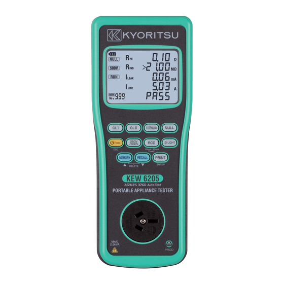
2.4 Tester layout Connector Display(LCD) Switches Connector 2.4.1 Function Switches Switch Details Short press: Starts CLI test. (Continuity test: 1 sec.) switch Long press: Starts CLI test. (Continuity test: 5 sec.) CLII Starts CLII test. switch Short press: Starts Extension lead test. Extension (Continuity test: 1 sec.) switch... - Page 9 Switch Details Short press: Works as ESC switch. Returns Power to the stand-by screen when switch a test is halted by “FAIL” result. Long press: Turns on/ off the Tester. Switches output voltage for insulation 250V resistance test between 250 V and 500 /500V V.
-
Page 10: Lcd Indications
2.4.2 LCD indications <All symbols to be displayed on the LCD> Display symbols NULL value has been set. Rated voltage for insulation resistance test Leakage current test under actual working condition Rated current for RCD test Measurement in progress Protective conductor resistance Insulation resistance Insulation resistance between L-N (Extension Lead Test) - Page 11 Mains voltage Polarity test result Indicates items failed the test. RCD test range Prompts to check and turn on a DUT. Indicates the connection for RCD test is incorrect. Indicates the resistance between L-L (N-N) is less than 10 Ω and polarity is correct.
-
Page 12: Connector
2.4.3 Connector (1) Test socket Insert the mains plug of DUT to this socket for the polarity test of protective conductor resistance, insulation resistance and leakage current test. (2) Terminal for This terminal is connected to a mains mains lead supply via MODEL7277. -
Page 13: Accessories
2.5 Accessories (1) Mains lead MODEL7277 This mains lead can be connected to the mains supply so that the Tester supply power to the DUT. (2) Test Lead with safety alligator clip (MODEL7129A) and Probe with Blade type Prod(MODEL7161A). The probe and alligator clip are interchangeable. -
Page 14: Optional Accessories
2.6 Optional accessories (1) Printer cable MODEL7275 (2) USB cable with "KEW Report(Software)" MODEL8263-USB ̶ 13 ̶... -
Page 15: Specification
3. Specification 3.1 General specification, measuring range and accuracy Mains voltage indication: Display range 30 - 270 V Hi/ Lo indication < 30 V: No voltage indication > 270 V: >270 V Resolution Accuracy ±5 V * Voltage between L-N of mains lead terminal is measured and displayed at voltage test. - Page 16 Leakage current test under actual working condition: (Load current is also measured.) Item Load current Leakage current Mains voltage 100 - 253 V/ 50 Hz range Measuring range 0.10 - 10.00 A rms 0.10 - 20.00 mA rms Display range 0.00 - 12.00 A 0.00 - 21.00 mA Over-range...
-
Page 17: General Specification
3.2 General specification Reference conditions Specifications are based on the following conditions, except where otherwise stated: - (1) Ambient temperature: 23±5˚C (2) Relative humidity: 45 - 75% (3) Attitude: Horizontal (4) AC power supply: 230 V, 50Hz (5) Altitude: 2000m or less Battery type Six size AA alkaline batteries (LR6) -
Page 18: Threshold And Display
Symbols used on the Tester: Electrical circuits of equipment connected to an AC CAT II electrical outlet by a power cord. Double or reinforced insulation User must refer to the explanations in the instruction manual. Earth ATT (Anti-Trip Technology) The Tester uses mains voltage across L-N for PRCD testing.It enables PRCD testing without tripping the RCD of mains power. -
Page 19: Preparation Before A Measurement
4. Preparation before a measurement 4.1 Visual inspection Before starting a measurement, the user should undertake visual checks on the mains lead, case and that the correct type and rated fuse is fitted to the appliance under test. There should also be no evidence of damage of a nature that may impair the electrical safety of the appliance. -
Page 20: Voltage Setting For Insulation Resistance Measurement
(3) The screen switches to NULL screen, and NULL measurement starts. The LCD shows blinking “MEAS” mark and measured value during a measurement. The measured value is saved and subtracted from the further measured values. (4) If the measured value is less than 3 Ω, previous NULL value is cleared and a new value is saved. -
Page 21: Measuring Method
5. Measuring method 5.1 Class I Test The purpose of the test carried out for Class I appliances is to check the resistance of earth continuity from exposed metal parts and the plug is below a certain level and the insulation resistance between live and neutral connected together and earth is 1MΩ... - Page 22 CL I Test Flow Stand-by Press to halt a (1sec.) measurement in progress. Tester performs next Voltage value is displayed test when CL I switch while the Tester is connected is pressed while a test to an outlet. is halted with “FAIL” Press CLI to start a test.
- Page 23 Rins≧1MΩ = PASS Rins<1MΩ = FAIL (Red backlight blinks.) Check screen for RUN leakage test. Buzzer sounds and blue backlight blinks. CLⅠ RUN Leak/ Load current test ILEAK≦5mA = PASS ILEAK>5mA= FAIL (Green backlight blinks.) (Red backlight blinks.) ̶ 22 ̶...
-
Page 24: Class Ll Test
# WARNING ● When conducting a leakage test the appliance will automatically power on and will operate in its normal manner. It is imperative that the appliance is secured safely before the test is carried out. Extra care needs to be taken with appliances which have heating elements and rotating parts. - Page 25 Connect to exposed metal parts but not rotating parts or heating elements. Switch ON the power. RUN leak test: Connect Tester to outlet Press CLII switch to perform Class II test. 1. Insulation Between LINE, NEUTRAL test and EARTH. 2. Leakage RUN Leak test: current test Connect Tester to outlet.
- Page 26 CL II Test Flow Stand-by state Press to halt a (1sec.) measurement in progress. Tester performs next Voltage value is displayed test when CL II switch while the Tester is connected to an outlet. is pressed while a test is halted with “FAIL” indication.
- Page 27 Rins≧1 MΩ = PASS Rins<1 MΩ = FAIL (Red backlight blinks.) Check screen for RUN leakage test. Buzzer sounds and blue backlight blinks. CLⅡ RUN Leak/ Load current test ILEAK≦1mA = PASS ILEAK>1mA = FAIL (Red backlight blinks.) (Green backlight blinks.) ̶...
- Page 28 # CAUTION ● Where DUT ON Check function detects the DUT is off, blinking ” OFF?” appears in the LCD and the test is stopped. Turn on the DUT; then the Tester automatically resumes the test. Depending on DUTs, even they are turned on, blinking ”...
-
Page 29: Extension Leads Test
5.3 Extension Leads Test This test is for extension leads, and checks for; ● Protective conductor resistance between accessible conductive parts and connection of protective earth. ● Insulation resistance between L/N and PE. ● Insulation test between L-N ● Polarity check of the Line and Neutral terminal of plug and socket ●... - Page 30 Extension Lead test flow Stand-by Press to halt a (1sec.) measurement in progress. Tester performs next test when Extension switch is pressed Extension while a test is halted Press to start a test. Short press: 1 sec of continuity test with “FAIL”...
- Page 31 Polarity check Polarity of L and N is Break in L or N Polarity of L and N is correct. reversed. (Cross) (Open) (Pass) (Red backlight blinks.) (Red backlight blinks.) Check screen for RUN leakage test. Buzzer sounds and blue backlight blinks. EXTENSION RUN Leak test ILEAK≦1mA =...
- Page 32 # CAUTION ● Follow the procedure described in 4.3.1 and do Null setting before a measurement, but use the short MODEL7276 lead instead of the MODEL 7129A test lead, by plugging the MODEL 7276 into the Extension Lead Adaptor terminal and the AU socket on the front of the unit.
-
Page 33: Rcd Test
5.4 RCD TEST (1) PRCD test This test is to test and confirm a PRCD (Portable Residual Current Device) trips within the rated time by applying specified current. The Tester incorporates a circuit to test PRCD with Rated Tripping Current (IΔn) of 10 mA or 30 mA. PRCD trip time is measured in sequence: ×1(0°)→×1(180°)→×5(0°)→×5(180°). - Page 34 RCD Test Flow Press to halt a (1sec.) Stand-by measurement in progress. Long press switches I∆n: 10 mA and 30 mA RCD test stand-by screen 10mA 30mA ×1(0°) test ×1( 0°) test result Reset the tripped RCD. ̶ 33 ̶...
- Page 35 ×1(180°) test ×1( 180°) test result Reset the tripped RCD. ×5(0°) test ×5( 0°) test result Reset the tripped RCD. ×5(180°) test Test results are all "PASS": If any one of test results is "FAIL": "PASS" is displayed. "FAIL" is displayed. (Green backlight blinks.) (Red backlight blinks.) ̶...
- Page 36 S- type, should be taken into consideration. ● ATT (Anti-Trip Technology) The KEW6205 uses mains voltage across L-N for PRCD testing. It enables PRCD testing without tripping the RCD of mains power. It works with the connection for "(1) PRCD test" as shown above;...
-
Page 37: Memory/ Recall Function
6. Memory/ Recall function 6.1 Memory function Test results on each function can be saved with this function. Press the Memory switch to save the displayed result. (Max: 999). Hold down the Memory switch for a while to edit the data no., site no. and device no. -
Page 38: Recall Function
6.2 Recall function This function is to recall and display the saved data on LCD. To see the date, site no. or device no., recall the saved data on the LCD and then press the RCD switch. The data recalled with this function can also be printed out. -
Page 39: Delete The Saved Data
6.3 Delete the saved data Hold down the Memory and Recall switch simultaneously while the saved data is displayed on the LCD by using Recall function. (Data won’ t be cleared at this moment.) Select to delete just one result or all results. -
Page 40: Print Function
7. Print function Test results displayed on the LCD can be transferred to a printer by pressing the PRINT switch. Use the optional printer cable MODEL7275 to connect a printer and the instrument. Long press of the PRINT switch can toggle and change the site no. or device no. for print. - Compatible printer: TLP2824PLUS (Zebra) The table below shows the communication specs. - Page 41 Data can be printed out according to the following sequence. Screen showing the measured/ recalled result PRINT(Long press) POWER(ESC) [ Site No. edit screen ] [Site No./ Device No. edit screen ] Press MEMORY switch to increase the number by 1. Blink Press RECALL switch to decrease the number by 1.
-
Page 42: Usb Communication
8. USB communication This instrument has USB communication to transfer the internal data to a PC. Data can be edited by using the special application KEW Report. Use the optional USB cable MODEL8263 to connect the instrument and a PC. The table below shows the USB communication specs. -
Page 43: Clock Mode
9. Clock mode A long press of backlight switch on any screen shows the current time. To adjust the time, press the PRINT switch while the time is being displayed. The time can be adjusted according to the following sequence. On any screen LIGHT(Long press) POWER(ESC) -
Page 44: Backlight
10. Backlight Press the backlight switch to turn on the backlight. Press the switch again to turn off the backlight. The backlight automatically turns off if there is no activity for about 2 min. 11. Battery / Fuse replacement # DANGER Never open the Battery cover during a measurement. -
Page 45: Fuse Replacement
11.2 Fuse Replacement (1) Disconnect the test probe from the Tester. (2) Unscrew the captive and open the battery compartment cover to replace the fuse. Fuse type: 10A/250V(F) Fast acting type ceramic fuse Φ 5 x 20mm. (3) Screw the battery cover back on before using the Tester. -
Page 46: Maintenance
(3) Pass the strap belt down through the buckle from the top, and up. Adjust the strap for length and secure. 13. Maintenance Use a very slightly damp cloth for cleaning the Tester. Do not use abrasives or solvents. ̶ 45 ̶... - Page 48 DISTRIBUTOR Kyoritsu reserves the rights to change specifications or designs described in this manual without notice and without obligations. 02-18 92-2304...
Need help?
Do you have a question about the KEW6205 and is the answer not in the manual?
Questions and answers