
Related Manuals for KYORITSU KEW 2413F


Summary of Contents for KYORITSU KEW 2413F
- Page 1 INSTRUCTION MANUAL DIGITAL CLAMP METER KEW SNAP Series KEW 2413F KYORITSU ELECTRICAL INSTRUMENTS WORKS, LTD.
-
Page 2: Table Of Contents
Contents 1.Safety Warnings ………………………………………………………1 2.Features ………………………………………………………………4 3.Specifications … ………………………………………………………5 4.Instrument Layout ……………………………………………………9 5.Operation 5−1 Preparation ……………………………………………………11 5−2 AC Current Measurement ……………………………………11 5−3 How to Use Peak Hold Function ……………………………14 5−4 How to Use The Frequency Selector Switch ………………16 5−5 How to Use Data Hold Function ……………………………17 5−6 Analogue Output How to Use Model 7073 Output Cord …17 6.Battery Replacement …………………………………………………19 7.Cleaning ………………………………………………………………20 8.Before Sending For Repair …………………………………………21... -
Page 3: 1.Safety Warnings
● S ave and keep the manual handy to enable quick reference whenever necessary. ● T he instrument is to be used only in its intended applications. ● U nderstand and follow all the safety instructions contained in the manual. F ailure to follow the instructions may cause injury, instrument damage and/or damage to equipment under test. Kyoritsu is by no means liable for any damage resulting from the instrument in contradiction to this cautionary note. ̶ 1 ̶... - Page 4 ● D o not install substitute parts or make any modification to the instrument Return the instrument to Kyoritsu or your distributor for repair or re-calibration. ● D o not try to replace the battery if the surface of the instrument is wet. ̶ 2 ̶...
- Page 5 CAUTION ● D o not expose the instrument to the direct sun, extreme temperatures or dew fall. ● B e sure to set the function selector switch to the OFF position after use. When the instrument will not be use for a long period of time, place it in storage after removing the battery. T his is to avoid damage to the instrument by possible leakage from the battery. ● ...
-
Page 6: 2.Features
2.Features KEW 2413F is a unique digital clamp meter for both very low current and high current measurements. Its shielded transformers jaws minimizes the effect of external stray magnetic field, enabling leakage current measurements. ● M easures from 0.1mA to 1000A AC and provides frequency response higher than 1kHz on all measuring ranges. M easurements also possible with approximately − 7% accuracy at 20 kHz on 200mA range. -
Page 7: 3.Specifications
3.Specifications Measuring Ranges and Accuracy ●AC Current Accuracy Time Limit for Ranges Frequency Range Response Measurements WIDE 50/60Hz 200mA 0〜199.9mA ±1.0%rdg±2dgt (50/60Hz) 2A 0〜1.999A ±1.5%rdg±2dgt ±3.0%rdg±2dgt (40〜1kHz) 20A 0〜19.99A ±1.5%rdg±2dgt (50/60Hz) ±2.0%rdg±2dgt Continuous 200A 0〜199.9A ±3.5%rdg±2dgt (40〜1kHz) ±1.5%rdg±2dgt (50/60Hz) 0〜500A ±2.0%rdg±2dgt ±3.5%rdg±2dgt (40〜1kHz) 1000A ±5%rdg (50/60Hz)... - Page 8 Analogue Output (Output impedance: Approx. 1k Ω ) ●AC Output Range Measuring Range AC Output Voltage Accuracy 200mA 0〜200mA 0〜2A ±2%rdg 0〜200mV 0〜20A 200A 0〜200A ±2.5%rdg 0〜500A 0〜50mV ±3%rdg 1000A 501A〜1000A 50〜100mV ±5%rdg * V oltage proportional to the current under test is output with WIDE frequency ...
- Page 9 ●DC Output Accuracy (Frequency Range) AC Input DC Output Freq. Selector Freq. Selector Ranges Current Voltage Switch at Switch at 50/60Hz WIDE position Position 200mA 0〜200mA 0〜2A ±3%rdg ±3.5%rdg 0〜200mV 0〜20A 200A 0〜200A ±3.5%rdg ±4.0%rdg 0〜500A 0〜50mV ±5%rdg ±5.5%rdg 1000A 501A〜1000A 50〜100mV ±7%rdg ±7.5%rdg * D C voltage is output in proportion to the display reading, which reflects ...
- Page 10 Power Source :One 6 F22 or equivalent battery Low Battery Warning : B symbol is shown on the display. Current Consumption :Approx. 5mA max. Standard(Safety) :IEC61010-1 IEC61010-2-032 CAT. Ⅲ ,AC300V,Pollution degree 2 (EMC) :IEC61326-1 Environmental Standards :EU RoHS Directive compliant Overload Protection :1500A AC max for 1 minute Withstand Voltage : 3 470V AC for 5 seconds between electrical circuit and housing cases Insulation Resistance ...
-
Page 11: 4.Instrument Layout
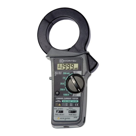
4.Instrument Layout Fig.2 ̶ 9 ̶... - Page 12 ① LCD F ield effect liquid crystal display with maximum indication of 1999. F unction symbol (mA, A) and decimal point automatically appear as the function / range switch is turned. B is displayed on the lower left corner for low battery warning and 1 is displayed only at the highest digit for overrange indication. ② Data Hold Button A llows for easy reading in dimly lit or hard-to-reach-locations. The display can be observed away from the conductor after pushing in ...
-
Page 13: 5.Operation 5−1 Preparation
5.Operation 5−1 Preparation (1) T o Check battery set the function/range switch (5) To the desired position. If the display is clear without symbol B showing, battery voltage is sufficient. If the display blanks or B is indicated, replace the battery in accordance with the battery replacement procedures as described in section 6. Note: B a l s o a p p e a r s o n t h e d i s p l a y w h e n t h e b a t t e r y becomes exhausted during use. Replace with a new battery. - Page 14 CAUTION ● T ransformers jaws , especially their tips, have been precisely adjusted to obtain maximum accuracy. Take sufficient care to avoid shock, vibration or excessive force when handing the instrument. ● W hen a foreign substance is stick in the jaw tips or they cannot properly engage, the transformer jaws do not fully close. In such a case, do not release the jaw trigger suddenly or attempt to close the transformer jaws by applying external force. Make sure ...
- Page 15 Note: W hen measuring large current, observe the time limit specified in section 3, Specifications. Otherwise, the transformers jaws may overheat, resulting in damage to the instrument. ̶ 13 ̶...
-
Page 16: 5−3 How To Use Peak Hold Function
5−3 How to Use Peak Hold Function 10ms or 100ms response time can be selected for peak hold measurement. Make selection according to your application needs. (1) W ith the transformer jaws clamped onto the conductor under test, slide the peak hold switch from the OFF position to the desired peak response time position. - Page 17 Note 2: I f it is necessary to read the display away from the conductor in a peak hold measurement, press the data hold switch (2) first and then remove the instrument from the conductor. Otherwise, the peak hold reading may be higher than the actual value due to the electrical noise caused by the opening and closing of the transformer jaws. Press the data hold switch again for a reset. (4) D ifference between 10ms and 100ms Peak Response Time T he peak hold circuit in this instrument charges the peak-hold capacitor after rectifying the input waveform. The time for the voltage ...
-
Page 18: 5−4 How To Use The Frequency Selector Switch
5−4 How to Use The Frequency Selector Switch KEW 2413F has a very good frequency response because of the electromagnetic property of its transformers jaws. Therefore, it measured, AC current not only of fundamental frequency of 50Hz or 60Hz, but of high frequencies and harmonics superimposed on the fundamental ... -
Page 19: 5−5 How To Use Data Hold Function
5−5 How to Use Data Hold Function Push in the Data Hold button to freeze the reading. This is especially useful for taking a reading in a dimly lit or hard-to-reach locations. The display can be observed away from the conductor. Push the button again to release the reading. 5−6 Analogue Output: How to Use Model 7073 Output Cord AC ... - Page 20 ̶ 18 ̶...
-
Page 21: 6.Battery Replacement
6.Battery Replacement Replace the battery when B symbol appears on the LCD display. (1) Set the function/range switch to the OFF position. (2) U nscrew and remove the battery compartment cover from the rear of the case. (3) I nstall a new 9V battery of type 6F22 or equivalent observing correct polarity. (4) Screw the battery compartment cover. WARNING Never replace the battery during measurement. ̶ 19 ̶... -
Page 22: 7.Cleaning
7.Cleaning Use a damp cloth detergent for cleaning the body of the instrument. To avoid possible deforming or discoloring, do not use solutions containing solvent. CAUTION ● N ever use paint thinner, benzene or other solutions containing solvent for cleaning the instrument. Otherwise, deforming or discoloring of the instrument body may result. ● H andle the instrument with care and follow the instructions in order to maintain it in good condition for a long period of time. ̶ 20 ̶... -
Page 23: 8.Before Sending For Repair
8.Before Sending for Repair Use the following troubleshooting guide for hints on problems with instrument operation. Condition Possible Cause Remedy Display blanks after power- B a t t e r y i s i m p r o p e r l y Install the battery correctly. - Page 24 DISTRIBUTOR Kyoritsu reserves the rights to change specifications or designs described in this manual without notice and without obligations. 6̶22 92̶1943A...
Need help?
Do you have a question about the KEW 2413F and is the answer not in the manual?
Questions and answers