
Subscribe to Our Youtube Channel
Related Manuals for Morris WFOD-26133


Summary of Contents for Morris WFOD-26133
- Page 1 WFIN-26132/WFOD-26133 √ WFIN-35132/WFOD-35133 √ WFIN-50132/WFOD-50133 √ WFIN-70132/WFOD-70133 √ Split type Inverter Air Condi oner USER MANUAL...
-
Page 2: Table Of Contents
CONTENTS I N T R O D U C T I O N T O REFRIGERANTS R32/R290 ......1 .......2 SAFETY PRECAUTIONS ..........5 NAMES OF PARTS ........6 INDOOR UNIT DISPLAY EMERGENCY FUNCTION & AUTO-RESTART FUNCTION .......7 REMOTE CONTROLLER ........8 ......11 OPERATING INSTRUCTIONS ........18 INSTALLATION MANUAL MAINTENANCE... -
Page 3: Introduction To Refrigerants R32&R290
INTRODUCTION TO REFRIGERANTS R32&R290 Introduction to Refrigerants R32 & R290 The refrigerants used for air conditioners are environmentally friendly hydrocarbons R32 and R290. The two kinds of refrigerants are combustible and odorless. Moreover, they can burn and explode under certain condition. However, there will be no risk of burning and explosion if you comply with the following table to install your air conditioner in a room with an appropriate area Compared with ordinary refrigerants, Refrigerants R32 &... -
Page 4: Safety Precautions
SAFETY RULES AND RECOMMENDATIONS FOR THE INSTALLER Read this guide before installing and using the appliance. During the installation of the indoor and outdoor units the access to the working area should be forbidden to children. Unforeseeable accidents could happen. Make sure that the base of the outdoor unit is firmly fixed. - Page 5 SAFETY RULES AND RECOMMENDATIONS FOR THE USER Do not try to install the conditioner alone; always contact specialized technical personnel. Cleaning and maintenance must be carried out by specialised technical personnel. In any case disconnect the appliance from the mains electricity supply before carrying out any cleaning or maintenance.
- Page 6 SAFETY RULES AND PROHIBITIONS Do not bend, tug or compress the power cord since this could damage it. Electrical shocks or fire are probably due to a damaged power cord. Specialised technical personnel only must replace a damaged power cord. Do not use extensions or gang modules.
-
Page 7: Names Of Parts
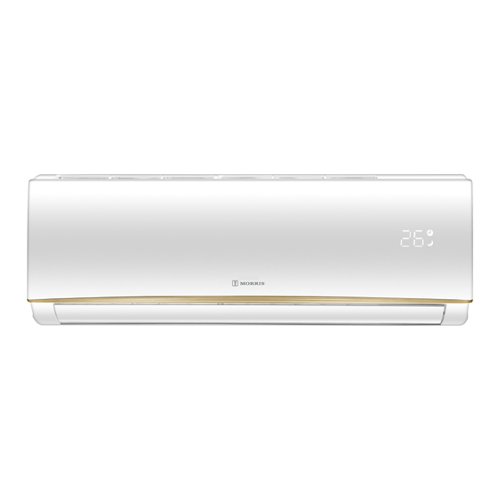
NAMES OF PARTS INDOOR UNIT INDOOR UNIT Description Front panel Air filter Optional filter (if installed) LED Display Signal receiver Terminal block cover Ionizer generator (if installed) Deflectors Emergency button Indoor unit rating label ( S ck posi on op onal Airflow direction louver Remote controller OUTDOOR UNIT... -
Page 8: Indoor Unit Display
INDOOR UNIT DISPLAY Function SLEEP mode SLEEP (1) Lights up during Timer operation when Temperature display (if present) the air conditioner is operational /Error code (2)Displays the malfunction code when fault occurs. TIMER Lights up during Timer operation. The shape and position of switches and indicators may be different according to the model, but their function is the same. -
Page 9: Emergency Function & Auto-Restart Function
EMERGENCY FUNCTION & AUTO-RESTART FUNCTION AUTO-RESTART FUNCTION The appliance is preset auto - restart function by manufacturer. In case of a sudden power failure, the ON / OFF module memorizes the setting conditions before the power failure. when the power restores, the unit restarts automatically with all the previous settings preserved by the memory function. -
Page 10: Remote Controller
REMOTE CONTROLLER Buttor Function (TEMP UP) Press it to increase temperature / time setting. (TEMP DN) Press it to decrease temperature/ time setting. ON/OFF Press it to start or stop operation. To select the fan speed of auto/low/mid/high Press it to set auto-off timer. TIMER SLEEP To activate the function SLEEP... - Page 11 REMOTE CONTROLLER Remote controller DISPLAY Meaning of symbols on the liquid crystal display Symbols Meaning FEEL mode indicator COOLING indicator DEHUMIDIFYING indicator FAN ONLY OPERATION indicator HEATING indicator SIGNAL RECEPTION indicator TIMER OFF indicator TIMER ON indicator AUTO FAN indicator (FLASH) LOW FAN SPEED indicator MIDDLE FAN SPEED indicator...
- Page 12 REMOTE CONTROLLER Replacement of Batteries Remove the battery cover plate from the rear of the remote controller, by sliding it in the direction of the arrow. nstall the batteries according the direction (+and -)shown on the Remote Controller. Reinstall the battery cover by sliding it into place. Use 2 LRO 3 AAA (1.5V) batteries .
-
Page 13: Operating Instructions
OPERATING INSTRUCTIONS The air sucked by the fan enters from the grill and passes through the filter, then it is cooled/dehumidified Filter or heated through the heat exchanger. Heat Exchanger The direction of the air outlet is motorized up and down by flaps, and manually moved right and left by the vertical deflectors. - Page 14 OPERATING INSTRUCTIONS COOLING MODE The cooling function allows the air condit- COOL ioner to cool the room and at the same time reduces Air humidity. To activate the cooling function ( COOL ) , press the MODE button until the symbol ( COOL) appears on the display.
- Page 15 OPERATING INSTRUCTIONS TIMER MODE----TIMER ON To set the time of the air conditioner TIMER To program the automatical switching-on time, the appliance should be power off. Press TIMER at the fist time , set the temperature with MODE TIMER pressing the button SLEEP DISPLAY Press TIMER at the second time , set the rest time with...
- Page 16 OPERATING INSTRUCTIONS FAN MODE The conditioner works in only ventilation. To set the FAN mode , Press MODE untill ( FAN) appears in the display. Whith pressing button the speed changes in the following sequence: LOW/ MEDIUM/HIGH MODE TIMER /AUTO in FAN mode. The remote control also stores the speed that was set SLEEP DISPLAY...
- Page 17 OPERATING INSTRUCTIONS FEEL MODE Automatic mode. FEEL To activate the FEEL (automatic) mode of operation, press the MODE button on the remote controller until the symbol ( FEEL) appears on the display. In FEEL mode the fan speed and the temperature MODE TIMER are set automatically according to the room temperature...
- Page 18 OPERATING INSTRUCTIONS I SET func on In each mode of COOLING/HEATING/FAN/DRY, adjust the temperature(COOLING/HEATING), fan speed (COOLING/ HEATING/FAN)and swing as your favourite, then keep pressing "I SET" button over 3 seconds until "AU" appears on the display and the background of display change to lighting, the remote controller will run and remember these settings.
- Page 19 OPERATING INSTRUCTIONS Operating Temperature The air conditioner is programmed for comfortable and suitable living conditions as below if used outside the conditions, certain safety protection features might come into effect., MODE Cooling operating Heating operating Drying operating Temperature 17°C~32°C 0°C~30°C 10°C~32°C Room temperature Outdoor...
-
Page 20: Installation Manual
INSTALLATION MANUAL---Important considerations Important Considerations The air conditioner you buy must be installed by professional personnel and the ΅Installation manual΅ is used only for the professional installation personnel! The installation specifications should be subject to our after-sale service regulations. When filling the combustible refrigerant, any of your rude operations may cause serious injury or injuries to human body or bodies and object or objects. - Page 21 INSTALLATION MANUAL---Important considerations The maximum charge and the required minimum floor area m = (4 m ) x LFL , m = (26 m )) x LFL, m = (130 m )x LFL Where LFL is the lower flammable limit in kg/ m ,R290 LFL is 0.038 kg/ m ,R32 LFL is 0.038 kg/ m . For the appliances with a charge amount m <...
- Page 22 INSTALLATION MANUAL---Important considerations Installation Safety Principles 1. Site Safety Open Flames Prohibited Ventilation Necessary 2. Operation Safety Open Flames Prohibited Mind Static Electricity Must wear protective clothing and anti-static gloves Don`t use mobile phone 3. Installation Safety Refrigerant Leak Detector Appropriate Installation Location The left picture is the schematic diagram of a refrigerant leak detector.
- Page 23 INSTALLATION MANUAL---Important considerations Special Tools Tool Name Requirement(s) for Use It should be an explosion-proof vacuum pump; can ensure certain precision and its Mini Vacuum Pump vacuum degree should be lower than 10Pa. It should be a special explosion-proof filling device; have certain precision and its Filling Device filling deviation should be less than 5g.
- Page 24 INSTALLATION MANUAL---Selecting the Installation Place INDOOR UNIT – Install the indoor unit on a strong wall that is not subject Mounting plate to vibrations. – The in let and outlet ports should not be obstructed:the air should be able to blow all over the room. –...
- Page 25 INSTALLATION MANUAL---Installation of the Indoor unit Before starting installation, decide on the position of the indoor and outdoor units, taking into account the minim- um space reserved around the units Do not install your air conditioner in a wet room such as a bathroom or laundry etc The installation site should be 250cm or more above the floor.
- Page 26 INSTALLATION MANUAL---Installation of the Indoor unit Refrigerant piping connection The piping can be run in the 3 directions indicated by numbers in the picture . When the piping is run in direction 1or3, cut a notch along the groove on the side of the indoor unit with a cutter.
- Page 27 INSTALLATION MANUAL---Installation of the Indoor unit INSTALLATION OF THE INDOOR UNIT After having connected the pipe according to the instruc- Covered by vinyl tape tions, install the connection cables. Now install the drain refrigerant insulation pipe. After connection,lag the pipe, cables and drain pipe pipe sleeve connection...
- Page 28 INSTALLATION MANUAL---Installation of the outdoor unit ELECTRICAL CONNECTIONS wiring diagram on the back of the cover 1. Remove the handle on the right side plate of outdoor unit. 2. Connect the power connection cord to the terminal board. Wiring should fit that of indoor unit. 3.
- Page 29 INSTALLATION MANUAL---Installation of the outdoor unit BLEEDING The air and humidity left inside the refrigerant circulat- 3-way valve diagram ion can cause compressor malfunction. After having co- connect to indoor unit nnected the indoor and outdoor units, bleed the air and humidity from the refrigerant circulation using a va- open position cuum pump.
- Page 30 INSTALLATION MANUAL---Information for the installer MODEL capacity (Btu/h) 18k/24k 9k/12k Lenght of pipe with standard charge Maximum distance between indoor and outdoor unit Additional refrigerant charge 15g/m 25g/m Max. diff. in level between indoor and outdoor unit Type of refrigerant(1) R32/R290 R32/R290 (1) Refer to the data rating label sticked on the outdoor unit.
- Page 31 INSTALLATION MANUAL---Information for the installer WIRING DIAGRAM For different models, the wiring diagram may be different. Please refer to the wiring diagrams pasted on the indoor unit and outdoor unit respectively. On indoor unit, the wiring diagram is pasted under the front panel; On outdoor unit, the wiring diagram is pasted on the backside of the outdoor handle cover.
- Page 32 INSTALLATION MANUAL---Information for the installer CABLE WIRES SPECIFICATION 18/22k INVERTER TYPE MODEL capacity (Btu/h) sectional area 1,5mm 1,5mm 2,5mm 2,5mm Power supply cable 1,5mm 1,5mm 2,5mm 2,5mm 1,5mm 1,5mm 2,5mm 2,5mm 1,5mm 1,5mm 2,5mm 1,5mm 1,5mm 1,5mm 2,5mm 1,5mm Connection supply cable 1,5mm 1,5mm 2,5mm...
-
Page 33: Maintenance
MAINTENANCE Periodic maintenance is essential for keeping your air conditioner efficient. Before carrying out any maintenance , disconnect the power supply by taking the plug out from the socket. INDOOR UNIT ANTIDUST FILTERS 1. Open the front panel following the direction of the arrow 2. -
Page 34: Troubleshooting
TROUBLESHOOTING MALFUNCTION POSSIBLE CAUSES Power failure/plug pulled out Damaged indoor/outdoor unit fan motor Faulty compressor thermomagnetic circuit breaker The appliance does not Faulty protective device or fuses. operate Loose connections or plug pulled out It sometimes stops operating to protect the appliance. Voltage higher or lower than the voltage range Active TIMER-ON function Damaged electronic control board... - Page 35 EMC-Directive: 14 / 30 / EU Low Voltage Directive: 14/ 35 / EU ErP Directive 09 / 125 / EC CE Marking: 93 / 68 / EEC RoHS Directive: 11 / 65 / EU The detailed declaration of conformity can be found at www.morris.gr...
- Page 36 EXCLUSIVE DISTRIBUTOR Amiridis - Savidis S.A. 87A, 17th November str. 55535, Pylea, Thessaloniki Tel. 2310 944944 Fax. 2316 006650 www.morris.gr...
Need help?
Do you have a question about the WFOD-26133 and is the answer not in the manual?
Questions and answers