Table of Contents
Advertisement
Quick Links
- 1 Table of Contents
- 2 The Detergent Circuit Has Not Been Loaded before Starting the Boiler
- 3 Poor or Missing Detergent Delivery Page
- 4 The Detergent Pump Is Damaged or Clogged or the Circuit Is Damaged or Has Leaks
- 5 Water Level Sensors that Determine the Level of Water for Dust Filtering into the Vacuum Tank, Are Intervened
- 6 Vacuum Turbine Not Working or the Suction Is Poor Page
- 7 Limestone Cleaning Procedure Page
- Download this manual
Advertisement
Table of Contents

Related Manuals for IPC SG-30 P 5510 M


Summary of Contents for IPC SG-30 P 5510 M
- Page 1 Service Manual Rev.1.0 February 2015 SG-30 P 5510 M...
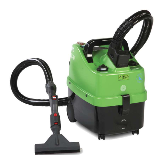
- Page 2 SG-30 outer layout Standard accessories kit (steam + vacuum) Standard handle (steam + vacuum) – length 2,5 m Water lack red lamp Steam ready green lamp Steam pressure gauge Steam flow adjustment Vacuum plug Water tank refill cap Electric controls plug Handle Detergent tank refill cap Not used...
- Page 3 SG-30 outer layout & handgrip Power supply cord Airflow exhaust silencer Electric controls plug Recovery tank hinges Recovery tank with water for air filtration Data plate Vacuum switch Chemical injection button Steam switch Pag. 3...
- Page 4 SG-30 functioning principle SG-30 is a steam generator suitable for professional continuous usage and provided with self-refill of water to the steam boiler, vacuum system to collect the dirt moisture and chemical injection combined with the steam stream. Water self-refill scheme Pag.
- Page 5 The heart of SG-30 is the steam boiler that is a stainless steel pressure vessel with heating elements inside to generate the steam. The steam generation follows physical rules and particularly the enthalpy rule that puts in direct relation the steam pressure and the steam temperature. Any steam generator, to achieve a certain temperature to the steam [°C], has a correspondent pressure [bar] as below.
- Page 6 SG-30 inner layout & components functionality description Steam flow adjusting valve Control switches Vacuum turbine Steam outlet line Chemical injection line Water pump to refill the boiler Steam electro valve Water tank with water level sensors (electrodes) Chemical tank with level sensors (electrode) Steam boiler with thermal insulation cover Chemical pump to ignite the chemical Vacuum pipe...
- Page 7 Water tank – the water tank has a capacity of 1,5 liters and is provided with electrodes that thanks to the water conductivity, detect the water level into the tank. The electrodes sensor is connected to the electronic board and in case the tank is empty, the water pump that refills the boiler is deactivated and the red lamp on the machine (water lack) is on.
- Page 8 Thermal insulation to prevent temperature dissipation and avoid temperature transmission to the other machine components. Boiler water feeding. Pressure control switch 5,5 bar that determines the Electrode to detect the water level inside of pressure and the the boiler temperature inside of the boiler.
- Page 9 Service Manual Ip Cleaning S.p.A. Viale Treviso, 63 – 30026 Summaga di Portogruaro – VENICE – ITALY Tel. +39 0421 205511 (r.a.) – Fax +39 0421 204227 Internet address: www.ipcportotecnica.com e-mail address: infoipcportotecnica@ipcleaning.com INDEX Topics 1. The machine doesn’t produce steam Page 1a No electrical connection or differential switch intervenes 1b No electrical supply to the heating elements of boiler, or...
-
Page 10: Table Of Contents
4. Poor or missing detergent delivery Page 4a The detergent circuit has not been loaded before starting the boiler 4b The detergent tank is empty 4c The detergent pump is damaged or clogged or the circuit is damaged or has leaks. 4d Electronic card burnt or damaged. - Page 11 1. The machine doesn’t produce steam 1) TROUBLE: Activating the “main power switch” and then one or both the switches “heating elements”, the pressure into the boiler doesn’t increase, neither after several minutes, since for this model the “steam ready” requires about 20’ until the heating elements generate the steam. Heating element 2, power switch Heating element 1, power switch Main power switch...
- Page 12 If the voltage is over or lower than the before mentioned tolerance, the machine electric components may damaged. Pay maximum attention while checking electric component: danger of electric shocks. If at the power socket there is a differential switch, be sure that the switch is on and not tripped out suddenly just after activating the machine power switches.
- Page 13 Vacuum socket removed and disconnected With the help of a pin or a screwdriver, push into the machine, the central pin of the plastic rivets that secure the two plastic cover shells. Pull to slide out the remaining part of the Detail of the plastic rivet without the central rivet that now is free to slide In case of difficulties, pull out the rivet using...
- Page 14 Remove the chemical tank cap and the bracelet that hold the cap to the tank Press the tanks down and pull up at the same time the cover until the cover shells are separated Pag. 14...
- Page 15 Levering with a screwdriver in order to remove the pressure gauge from the cover In order to facilitate the reassembling, secure Disconnect the capillary pipe from the pressure with a band the capillary pipe of the pressure gauge gauge Now the top shell can be completely removed Pag.
- Page 16 Check the main switch with a multimiter. At this stage, in order to check the thermal – amperometric fuse, is necessary to disconnect and remove completely the boiler from its frame; proceed as following described: Remove the plastic cap at the boiler top The wires light blue color are connecter to the fuse placed under the boiler Unscrew the outlet fitting and disconnect the pipe...
- Page 17 Disconnect the wire from the water level sensor Unscrew the drain cup at the Boiler disconnected boiler bottom Check the fuse using a Unscrew the nut that secure the Lift up the boiler to check multimeter boiler to the frame the fuse If the boiler is cold, but the thermal amperometric sensor is open (off), is necessary to replace it with a new sensor.
- Page 18 1b Pay maximum attention: danger of electric shocks. Disconnect the machine from the power supply before opening the shells, hence: Check, using a multimeter, the conductivity of the "heating elements" switches that are the two switches placed to the control panel that have the red button. Check the continuity of the safety thermostat that is place as in the following picture.
- Page 19 1c If the feeding water pump not supply water into the boiler, can be a problem to the pump itself, so is necessary to check it the pump is powered. Check using a multimeter the voltage at the pump. Check the voltage to the water pump and if the pump is out of order, replace it with a new...
- Page 20 If the above mentioned checks do not highlight any problem, can be a failure of the electronic card the cause of the water pump that not functioning. Remove the electronic card and replace it with a new card. Remove the water pump Cut the bands that secure the water pump Remove the insulation sponge Unscrew the screw of the electronic board...
- Page 21 Pull firmly to slide out the electronic board, hence disconnect the plugs and replace the electronic card with a new one. 1d If the electronic card may be burnt or damaged, follow the instruction at the point 1c to remove and replace it. Pag.
- Page 22 Electric diagram On which : • L – N – PE = Power supply line • TF = Thermal fuse • IC = Boiler switch • R1 = Switch to activate the full heating power • IA = Main switch that activate all controls •...
- Page 23 1e If the pressure switch does not function and blocked in position off, the boiler doesn’t heat and do not generates the steam. Remove the pressure switch and replace it with a new part. Disconnect the wires connected to the pressure switch, unscrew it and replace with a new part.
- Page 24 The machine produce steam into the boiler, but is not streamed at the lance. 2) TROUBLE: The green lamp “steam ready” is on but the steam is not streamed at the lance. CAUSES: 2a Electro-valve clogged or burnt 2b Outlet circuit clogged by limestone 2c Steam stream adjusting tap clogged by limestone or completely closed 2d Hand grip electric controls not work 2e Plug that connects hose and machine is not electrically connected...
- Page 25 Perform the limestone removal procedure described in the following chapter 7. Open the adjusting tap rotating clockwise the knob. Steam adjusting tap 2d The electric controls on the hand grip, are used intensively and after a certain time, may have problems and is necessary to replace them. Open the handgrip with a screwdriver and by using a solderer, disconnect and replace the defective one with a new part.
- Page 26 2g If the main switch is not closing, check it and replaced if necessary. Follow the instructions explained at the point 1a. Check the main switch with a multimiter. Pag. 26...
- Page 27 The steam delivery at the lance is very poor or extremely wet 3) TROUBLE: The stream of steam at the lance is very poor or is extremely wet and condenses too much on the cleaning surface. CAUSES: 3a Steam circuit clogged by limestone 3b Water level sensor not working or boiler fully filled with water 3c Electro-valve not opening completely (partially clogged) 3d Steam stream adjusting tap in position closed or clogged...
- Page 28 3c If the electro-valve do not opens completely (partially clogged), follow the instruction as per point 2a. 3d If the steam stream adjusting tap is in position closed or clogged, follow the instructions as per point 2e. 3e Sometime can happen that the steam leakages are inside the machine circuit or inside the accessories.
-
Page 29: Poor Or Missing Detergent Delivery Page
4. Poor or missing detergent delivery 4) TRUBLE: Poor detergent delivery CAUSES: 4a The detergent circuit has not been loaded before starting the boiler 4b The detergent tank is empty 4c The detergent pump is damaged or clogged or the circuit is damaged or has leaks. -
Page 30: The Detergent Pump Is Damaged Or Clogged Or The Circuit Is Damaged Or Has Leaks
4b If the detergent tank is empty, the sensor detects non detergent, so the detergent pump will not be activated. Refill the detergent tank with detergent or water. 4c The detergent pump is damaged or clogged or the circuit is damaged or has leaks. Check the voltage to the detergent pump when activated, in case of voltage, but the pump not working, replace it with a new pump. -
Page 31: Electronic Card Burnt Or Damaged
5. Vacuum turbine not working or the suction is poor 5) TROUBLE: Activated the vacuum motor, the vacuum to the accessory is very poor or the turbine do not function at all. CAUSES: 5a Vacuum motor/turbine burnt or damaged 5b Handgrip vacuum control switch not working 5c Plug that connects hose and machine is not electrically connected 5d Electronic card burnt or damaged. - Page 32 5c If the plug that connects hose and machine is not electrically connected the steam cannot be sprayed from the lance. Check both the plug and the socket and restore the electrical connections. 5d If the electronic card may be burnt or damaged, follow the instruction at the point 1c to remove and replace it.
-
Page 33: Steam Electro-Valve Defective Or Locked In Position Open
The steam delivery or the vacuum system are working continuously and cannot stop. 6) TROUBLE: Switched off the control switches on the handgrip, the steam stream do not stops. CAUSES: 6a Steam electro-valve defective or locked in position open 6b Switches placed on the handgrip defective or wires wired into the hose that are damaged and in short circuit. -
Page 34: Limestone Cleaning Procedure Page
Limestone cleaning procedure. On average, this operation should be carried out after every 100 hours of operation. If the appliance is used with especially hard water (>30°Fr), carry out maintenance more frequently. Important: all the operations described below must only be performed when the machine is cold, disconnected and out of service for at least 4 hours. - Page 35 3. Empty the water and residual limestone from the boiler 4. Close the drain cap located underneath the machine after having drained the boiler. It is advised to replace the o-ring of the cap (see spare parts manual). Pag. 35...
- Page 36 5. Open the machine cover and remove the level sensor located above the boiler 6. Fill the boiler with two liters of normal alimentary white vinegar 7. Clean and reinstall the level sensor 8. Connect the machine to the power supply 9.
- Page 37 Periodical maintenance Every day Every 50h Every 100h Every year Check the power cord and the steam couplings. Limestone cleaning procedure Check and adjust of the safety devices or components Lubricate the accessories coupling with silicone grease Pag. 37...
Need help?
Do you have a question about the SG-30 P 5510 M and is the answer not in the manual?
Questions and answers
Не прирывный писк, что значит?