Technica Engineering 1000Base-T1 SPY mini User Manual
1000base-t1 – standard ethernet
Hide thumbs
Also See for 1000Base-T1 SPY mini:
- User manual (13 pages) ,
- User manual (35 pages) ,
- User manual (23 pages)

Related Manuals for Technica Engineering 1000Base-T1 SPY mini


Summary of Contents for Technica Engineering 1000Base-T1 SPY mini
- Page 1 1000Base-T1 – Standard Ethernet 1000Base-T1_SPY_mini User Manual Version 1.1 August 2018 Technica Engineering GmbH Email: info@technica-engineering.de Leopoldstr. 236 80807 München Web: www.technica-engineering.de...
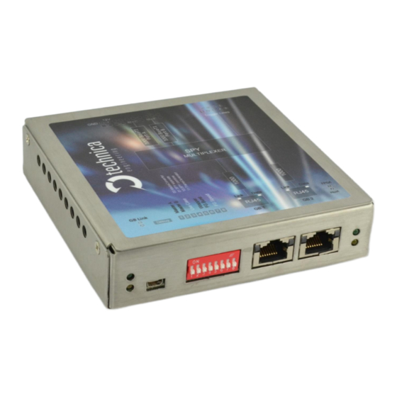
- Page 2 Note: This User Manual is related to the 1000Base-T1_SPY_mini FW 1.2.1. Figure 1: 1000BASE-T1_SPY_mini device age 2 of 21...
-
Page 3: Table Of Contents
Dual Media Converter Mode ...................10 Spy Mode Independent ..................11 Spy Mode Combined ....................12 Spy Mode with wrapper ..................13 6.4.1 1000Base-T1 SPY mini LUA Dissector Installation Guide ......14 802.1 AS Synchronization ..................16 6.5.1 802.1 AS Protocol ...................16 6.5.2 802.1 AS in 1000Base-T1 SPY Mini ..............17 Frequently Asked Questions –... -
Page 4: Feature List
1 Feature List The Technica Engineering 1000Base-T1 SPY mini samples 1000Base-T1 Frames directly on the bus without influence of the original network. The data Frames are enhanced with addi- tional in-formation as an exact timestamp and the bus port which the data was originally sent on. -
Page 5: Warranty And Safety Information
2 Warranty and Safety Information Before operating the device, read this manual thoroughly and retain it for your reference. Use the device only as described in this manual. Use only in dry conditions. Do not apply power to a damaged device. Do not open the device. -
Page 6: Connectors And Pinning
3 Connectors and Pinning The pinning of the ECU connectors is listed on the label on top of the device, detail infor- mation see below. Figure 2: Sticker Topview of device Power and 1000BaseT1 connector Power supply for the device is supplied by Pin 18 (12 Volt) and Pin 20 (Ground). Warning: If you apply a voltage higher than 18 Volt, the device will be damaged! The Tyco Electronics (TE) Nano Micro Quad Lock System (NanoMQS) is used. - Page 7 http://www.te.com/usa-en/product-2141404-1.html http://www.te.com/usa-en/product-2-1703930-1.html http://www.te.com/usa-en/product-4-1579014-0.html http://de.farnell.com/te-connectivity/2-1703930-1/contact-socket-crimp/dp/2528666 Official Crimp Tool: TE CONNECTIVITY CS11K NANO-MQS, 0.13-0.35 SQ.M TE Internal Number: 4-1579014-0 Distributor: Börsig GmbH Siegmund-Loewe-Str. 5 74172 Neckarsulm www.boersig.com Figure 3: Crimp Tool Pinning of nanoMQS: Function Function 1000Base-T1 Port_1, Negative n.c. n.c. 1000Base-T1 Port_2, Positive n.c.
-
Page 8: Subd 9 Trigger Connector
SubD 9 Trigger Connector Standard SubD 9 Pos. female connector. This connector is used for digital input and output trigger functions. Function Digital Trigger Input / Output 1 Digital Trigger Input / Output 2 Signal Ground Reference Signal Ground Reference Signal Ground Reference Digital Trigger Input / Output 3 Digital Trigger Input / Output 4... -
Page 9: Status Leds And Pushbutton
On when link is detected Table 3: description LEDs 5 Configuration The 1000Base-T1 SPY mini is configured by 8 DIP Switches on the front of the device. DIP Switch 1: = 1000Base-T1 Port 1 is set to Master. OFF = 1000Base-T1 Port 1 is set to Slave. -
Page 10: Use Cases
The simplest Use Case is the double Media Converter, selected by setting the DIP switches 3 and 4 to “00” (both switches down). The 1000Base-T1 Spy mini will act similar to completely independent Media Converters from 1000Base-T1 to Gigabit Ethernet in full-duplex mode. -
Page 11: Spy Mode Independent
Spy Mode Independent The user can select this mode by setting the DIP switches 3 and 4 to “01” (DIP Switch 3 down and DIP Switch 4 up). In this mode the copied data from the two 1000Base-T1 Ports are logged independently through the 2 Ethernets ports. -
Page 12: Spy Mode Combined
Spy Mode Combined The user can select this mode by setting the DIP switches 3 and 4 to “10” (DIP Switch 3 up and DIP Switch 4 down). In this mode the copied data from the two 1000Base-T1 Mbit/s are logged into one 1000Mb/s stream and are sent on one Gigabit link. -
Page 13: Spy Mode With Wrapper
With this feature the user can record the exact time when the first byte in the preamble field of a frame was received on a 1000Base-T1 port of the 1000Base-T1 SPY mini. It is also possible to see the complete frame including the preamble and the CRC in Wireshark. Normally this information is re-moved by your network interface. -
Page 14: 1000Base-T1 Spy Mini Lua Dissector Installation Guide
6.4.1 1000Base-T1 SPY mini LUA Dissector Installation Guide In order to dissect the 1000Base-T1 SPY mini RAW Ethernet Frames, a LUA file for Wireshark is available on Technica Engineering website. To install the LUA file in Wireshark, the user has to do the following steps:... - Page 15 1. Close Wireshark in case that the program is running on PC. 2. Download the .ZIP file that contains all the LUA files, through this website: https://technica-engineering.de/produkt/1000base-t1-spy-mini/ https://technica-engineering.de/wp-content/uploads/2018/06/1000Ba- seT1_SPY_Mini_Wireshark_Dissector.zip 3. Extract the downloaded ZIP file. This file should contain the following LUA file: 1000BaseT1_SPY_Mini_ETH_wrapper.lua 4.
-
Page 16: 802.1 As Synchronization
802.1 AS Synchronization When the user selects the SPY Combined Mode -see Chapter 6.3- with the Wrapper enabled -see Chapter 6.4-, the 802.1AS Synchronization is automatically enabled. With this functionality, the device will be able to synchronize with any Master Device. In this case, the device will use the same TimeStamping as the Master Device, and this includes the maintenance of synchronized time during normal operation and following addition, re- moval, or failure of network components and network reconfiguration. -
Page 17: 802.1 As In 1000Base-T1 Spy Mini
6.5.2 802.1 AS in 1000Base-T1 SPY Mini The 1000Base-T1 SPY Mini device works only as a Slave device, sending Request messages to the Master de- vice through GB2 port. Connecting a Master Device to this port, the device will synchronize its in-... -
Page 18: Frequently Asked Questions - Faq
7 Frequently Asked Questions – FAQ Q: What is the delay time for Ethernet packets between two 1000Base-T1 ports? A: For the SPY mode -independent or combined-, the delay between two BroadR-Reach ports is around 1.19µs. The delay is independent of the Ethernet packet frame size. Q: Is AVB supported? A: The SPY is especially built for testing AVB. -
Page 19: Change-Log
8 Change-Log Version Chapter Description Date Other Generation of user manual 01.06.2018 6.4 table 4 Correction of ethertype 06.08.2018 Rework 06.08.2018 Added new FAQ rework of Connector description 06.08.2018 age 19 of 21... -
Page 20: Contact
9 Contact If you have any questions regarding this product, please feel free to contact us: Technica Engineering GmbH Leopoldstr. 236 80807 München Germany Technical support: support@technica-engineering.de General information: Info@technica-engineering.de Most current user manuals and product information: https://technica-engineering.de/ age 20 of 21... - Page 21 age 21 of 21...
Need help?
Do you have a question about the 1000Base-T1 SPY mini and is the answer not in the manual?
Questions and answers