
Related Manuals for Technica Engineering CM CAN Combo


Summary of Contents for Technica Engineering CM CAN Combo
- Page 1 IVN2Eth Capture Module: CM CAN Combo USER MANUAL June 2020 Manual-Version: 1.0 Firmware: v012.00x.020 Hardware: v1.0 up to v3.1...
- Page 2 General Information ..................20 4.3.2 IP addresses ....................21 Control Panel Tab ....................22 4.4.1 Restart target ....................23 4.4.2 Configuration ....................23 4.4.3 Prevent Standby and Prevent Sleep ............25 4.4.3.1 Staying alive conditions ............... 26 CM CAN Combo User Manual...
- Page 3 Transport of time-synchronization information ........52 4.8.2 Propagation delay measurement ............... 53 4.8.3 How to setup a synchronized network with CaptureModules ....54 How to use Advance Filter ................. 55 4.9.1 General information ..................55 CM CAN Combo User Manual...
- Page 4 Complete ethernet frame containing a TECMP frame ........62 TECMP header ....................62 Control Message from CaptureModule ............65 Status Messages from CaptureModule ............65 ADDITIONAL INFORMATION ..................66 LIST OF FIGURES ....................... 67 CHANGELOG ......................69 CONTACT ....................... 70 CM CAN Combo User Manual...
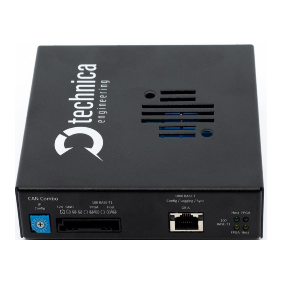
- Page 5 1.1 Functionality and Features of the CM_CAN_Combo Figure 1-1: Capture_Module_CAN_Combo The Technica Engineering Capture Module CAN Combo is used to capture the traffic from the conventional CAN busses, as well as CAN-FD, FlexRay and RS-232 can be captured without interfering the original networks.
- Page 6 133 x 130 x 33 mm Weight: 0.5 kg International Protection: IP 2 0 Operating temperature: -40°Celsius to 80°Celsius LINKS: The User can download the latest documentation for the CM_CAN_Combo here: https://technica-engineering.de/produkt/capture-module-can-combo/ For the latest firmware, please contact Support@technica-engineering.de CM CAN Combo User Manual...
- Page 7 Do not place the device near to highly flammable materials due to fire danger. Do not use the device above the specified operating temperature. The operating temperature is the ambient temperature of the installation space. CM CAN Combo User Manual...
- Page 8 This symbol is only valid in the European Union. If you wish to discard this product, please contact your local authorities or dealer and ask for the correct method of disposal. Technica Engineering GmbH is registered as manufacturer of the brand "Technica Engineering" and...
- Page 9 1.4 RoHS Cerificate of Compliance Figure 1-3: Copy of RoHS Certificate of Compliance CM CAN Combo User Manual...
- Page 10 Special version for high voltage networks Note: there are different software versions for the different hardware versions available. If a software update is needed, please see for more information HAPTER and which software is the correct one. CM CAN Combo User Manual...
- Page 11 CM_CAN_Combo Figure 2-1: Label of CM_CAN_Combo with pinning information Note: If you have a newer variant in black, you can see this information directly at the connectors on the front site or back site. CM CAN Combo User Manual...
- Page 12 Tyco, MQS Buchsengehäuse 10 Pol Black 1-929423-2 Tyco crimp contact 928999-1 Table 2-1: Parts of black MQS connector Note: You can use the official Tyco tool for these crimp contacts. A cheap variant is the crimp tool for “PSK” contacts. CM CAN Combo User Manual...
- Page 13 Advantage for using only 2 pins: there is no need to for a plugged CM_CAN_Combo while using the testsetup. Disadvantage for using 2 pins: The stub to the CAN-bus is as long as your cable. CM CAN Combo User Manual...
- Page 14 CAN-FD C Plus CAN-FD C Plus CAN-FD B Minus CAN-FD B Minus CAN-FD B Plus CAN-FD B Plus CAN-FD A Minus CAN-FD A Minus CAN-FD A Plus CAN-FD A Plus Table 2-4: Pinning of Tyco MQS Connector CM CAN Combo User Manual...
- Page 15 FlexRay A Plus FlexRay A Plus n.c. n.c. RS232 A RXD RS232 B RXD RS232 A Reference GND RS232 B Reference GND RS232 A TXD RS232 B TXD Table 2-6: Pinning of Tyco MQS Connector CM CAN Combo User Manual...
- Page 16 “F”. There will be no software reset. A power reset is needed. But if there is a power reset in this Rotary switch status, the CM_CAN_Combo will be reset to out of the box status. Complete configuration will be lost and set to default. CM CAN Combo User Manual...
- Page 17 These LEDs show the status of the connected devices to the 100BASE-T1-Port LED H: Connection to the Host/Microprocessor (1) LED F: Connection to the FPGA (2) LED “on” (static) indicates LinkUp LED blinking means communication on 100BASE-T1 Port CM CAN Combo User Manual...
- Page 18 2. Enter the IP Address in your standard web browser. For more information about the IP addresses see 2.2.1 4.3. HAPTER HAPTER Note: Chrome or Firefox are recommended. 3. The following website should appear Figure 3-1: Home Screen CM_CAN_Combo CM CAN Combo User Manual...
- Page 19 After the restart, all changes are applied. 4.2 Home Screen Figure 4-2: CM_CAN_Combo Home Screen By the first access to the website you will get the home screen. Please select one of the tabs for further configuration. CM CAN Combo User Manual...
- Page 20 The version of your MAX10 Software of the CM_CAN_Combo is displayed here. FPGA version: The version of your FPGA Software of the CM_CAN_Combo is displayed here. Application Software version: The current firmware version of your CM_CAN_Combo is displayed here. CM CAN Combo User Manual...
- Page 21 This is the IP address you get access to the Webserver by the 100BASE-T1 port (Host). This IP address can be changed here. Please type the new IP address in the field. After leaving the focus of this field or pressing “Enter” you can save the changes. CM CAN Combo User Manual...
- Page 22 “Enter” you can save the changes. 4.4 Control Panel Tab On this tabulator you can import/export the configuration and make general settings of the configuration. Figure 4-5: Control Panel CM CAN Combo User Manual...
- Page 23 Configuration name: You can change the name of the configuration from to “Default” to any other name. Spaces, numbers and + - _ ; : . are allowed. After saving the new name is applied. CM CAN Combo User Manual...
- Page 24 Then press the button “Submit Query”, Apply the changes by saving the configuration. Please check the box for restart. Default: This button resets the CM_CAN_Combo to default configuration, but not the default IP addresses! CM CAN Combo User Manual...
- Page 25 The CM_CAN_Combo works at full capacity as long as there is communication on supervised ports. If there is no communication for defined time in field Sleep Timeout, the CM_CAN_Combo falls asleep. The boxes must be checked like this: Prevent standby Prevent sleep CM CAN Combo User Manual...
- Page 26 (kind of loop through). It provides power as long as there is a reason to stay awake. WakeUp Line 1 Actuator: If this box is unchecked, this wakeup line is only input and wakes up the device when supplied. CM CAN Combo User Manual...
- Page 27 Here you define the time in seconds, which has to go by before the actuator of the wakeup lines is set to ground. The starting point of time counter is the same time as there is no reason anymore to be awake of the CM_CAN_Combo itself. Default value is 10 seconds. CM CAN Combo User Manual...
- Page 28 By this field you can set the time of the Capture Module in shown format for the timestamp in the TECMP-protocol. Just type the date and time in the format as follows: YYYY-MM-DDThh:mm:ss After typing please press CM CAN Combo User Manual...
- Page 29 This is an overview of all ports. A blue bar indicates the linkup status on this port. If you select a port or any other part of the CM_CAN_Combo, it is shown by blue text of the selected part. CM CAN Combo User Manual...
- Page 30 [0x99FE]: The header of each logged frame gets the ethertype 0x99FE and the header is a TECMP header Legacy Mode [0x2090]: The header gets the ethertype 0x2090. The protocol is very similar. Some fields have a different name but in general, the functionality is the same. CM CAN Combo User Manual...
- Page 31 Values for Timeout [ms] can be between 100ms and 65535ms. 4.5.1.5 Logging Ports for Packetization Here you define, which port is using packetization. GB-A is using packetization GB-A is using no packetization Note: Only one port can use packetization at the same time. CM CAN Combo User Manual...
- Page 32 There is a hint in red text on the website of the CaptureModule. And this information can be found in the status messages CM CAN Combo User Manual...
- Page 33 (in current picture no filter shown). These basic filters can be edited by the button Edit Table. The button Edit Advance Filter opens an editable list of Advance Filter. CM CAN Combo User Manual...
- Page 34 Add new entry: adds a new line in the table Apply: This Button at the bottom will apply the Filter Entries. For saving them permanently, please save the configuration and restart the device. CM CAN Combo User Manual...
- Page 35 Value: One value in defined format must be typed in this field CAN_ID: Hexadecimal, e.g. “1FB” Action: only one action is available DROP: Each message that matches the Filter Entry will not be mirrored to the logging port. It will be dropped. CM CAN Combo User Manual...
- Page 36 Edit Advance Filter (Figure 4-16) you can apply different advance filters for the captured data. 4-19 shows the user interface: IGURE Figure 4-19: User interface Advance Filter A maximum of 24 (0-23) rules is possible. CM CAN Combo User Manual...
- Page 37 Payload: Here you can define which payload of a CAN-message the filter has affect to Value: Here you define the value of your Field. Allowed values depend on the chosen Field. How to use Advance Filter: Please see HAPTER CM CAN Combo User Manual...
- Page 38 This port is supervised. If on this port is communication, CM_CAN_Combo can’t fall asleep or change into standby mode This port is not supervised. The Capture Module can fall asleep even there is communication on this port. CM CAN Combo User Manual...
- Page 39 This port is not supervised. The Capture Module can fall asleep even there is communication on this port. Working as Config-port (Default: GB-A): You can configure the Capture Module when connected on this port with your configuration PC and you get access to the webserver on this port. CM CAN Combo User Manual...
- Page 40 This is a table which shows all CAN, Flexray and RS232 ports and if the logging of each port is forwarded to this 100BASE-T1-port. CAN-A: CAN-A sends its logged information to this 100BASE-T1-port CAN-A: CAN-A does not send its logged information to this 100BASE-T1-port CM CAN Combo User Manual...
- Page 41 You can’t configure the Capture Module connected on this port with your configuration PC. There is no access to the webserver, except no other port is configured as config-port The status messages of the Capture Module are not transmitted on this port. CM CAN Combo User Manual...
- Page 42 This is a table which shows all CAN, Flexray and RS232 ports and if the logging- configuration of each port is linked to this 100BASE-T1-port. CAN-A: CAN-A sends its logged information to this 100BASE-T1-port CAN-A: CAN-A does not send its logged information to this 100BASE-T1-port CM CAN Combo User Manual...
- Page 43 • CAN 2.0 • Non ISO CAN-FD • ISO CAN FD Mode: Choose the CAN mode: • Passive Node (No ACK) • Active Node (ACK) rate: Choose the bit rate which depends on the CAN-Bus. CM CAN Combo User Manual...
- Page 44 [ns] (starting with epoch time, if no PTP master is connected) Messages Received: Counter for received messages on this port from the connected CAN-Bus Messages with Error: Counter for received messages on this port from the connected CAN-Bus containing an error. For example, CRC errors. CM CAN Combo User Manual...
- Page 45 If the device is in standby-mode and there is incoming traffic, the device will enter normal mode. For details see 4.4.3 HAPTER If the device is in sleep-mode and there is incoming traffic, the device will not enter normal mode and stay in standby-mode CM CAN Combo User Manual...
- Page 46 Here you can define the logging port of the incoming traffic on this port. None: no logging port defined => no logging possible 100Base-T1: 100Base-T1 port is defined as logging port (Not the Host!) GB-A: GB-A is defined as logging port CM CAN Combo User Manual...
- Page 47 TECMP-frame, which collects received messages on this port (one TECMP frame for more than one RS 232 message. For details see the TECMP-definition. Timeout: After this time the TECMP-frame is sent, even if the Max packet size is not reached. CM CAN Combo User Manual...
- Page 48 If there is anything already configured, after every software or hardware reset of the CM_CAN_Combo will start with XCP. Init: By clicking on this-Button, you can add new XCP requests. The following screen with two tables appears: CM CAN Combo User Manual...
- Page 49 BusId: It is the BusId from the CAN-Port, the XCP is activated CanIdReq: CAN-Id of the request Offset/ Repetition: not supported => empty Address: it is the starting address of memory range in the XCP slave CM CAN Combo User Manual...
- Page 50 *.json-file: Figure 4-30: Example of XCP Entries Please press Apply save the configuration to store it permanent. Values: BusId: It is the BusId from the CAN-Port the XCP is activated CM CAN Combo User Manual...
- Page 51 Apply: Here you can apply made changes of Figure 4-32: How to edit User Event list the list. To make the changes permanent, please save the configuration. 4.7.2 Values of Control Message Entries Control Message-ID: Arbitrary decimal value from 1 to 255 CM CAN Combo User Manual...
- Page 52 CaptureModule („Time-aware system I”) implements additionally then the respective opposite sides of the communication, one slave port and one master port, as shown in the next image. CM CAN Combo User Manual...
- Page 53 For the correction adjust of the time reference transmitted by the Sync and Follow Up Packets, the delay between the initiator of the protocol „Time-aware system i-1“ and the first slave port of CaptureModule „Time-aware system i“, should be measured CM CAN Combo User Manual...
- Page 54 The available ports for this synchronization are only the GB-Port and the 100B-T1 port at the frontside of the CaptureModule Note: If there is already one port defined as Bridge-slave there is no more a Bridge- slave-port or 802.1AS Master-port possible. CM CAN Combo User Manual...
- Page 55 ➔ select the open bracket ➔ choose in Field “Payload” ➔ press the button ➔ type the value 0C83 and press ENTER ➔ select the close bracket ➔ press the button ➔ save the changes. ➔ finished CM CAN Combo User Manual...
- Page 56 ENTER ➔ select the open bracket ➔ choose in Field “CAN ID” ➔ press the button ➔ type the value and press ENTER ➔ select the close bracket ➔ press the button ➔ save the changes. ➔ finished CM CAN Combo User Manual...
- Page 57 Please follow this update instruction to avoid erroneous states of the device. Technica Engineering may charge support fees for repair service. Only upgrade to the latest firmware. And always bootloader and application Firewall must be deactivated, or Port 69 and Port 9000 must be open You need a stable 12 Volt DC power supply.
- Page 58 This option requires a 100BASE-T1 MediaConverter (MC) or a MediaGateway to get access to the device by the 100BASE-T1 Port. The photos below shows the connection of the devices in case of Media Gateway usage with our MediaGateway-Configuration- File. Figure 5-1: Schematic with MediaConverter CM CAN Combo User Manual...
- Page 59 Figure 5-2: Schematic with MediaGateway Figure 5-3: Example of MediaGateway and Capture Module (here: CM_Eth_Combo) assembly Connect the Ethernet Cable to the Converter or to the MediaGateway and that device to the CM_CAN_Combo. CM CAN Combo User Manual...
- Page 60 Figure 5-4: Power and BroadR-Reach Connector for Capture Module Figure 5-5: MediaGateway connection in detail Note: It is recommended to use our *.cfg-file for the MediaGateway configuration. With this configuration the Media Gateway forwards the data from the S2-P5 directly to the BR-S2-P0. CM CAN Combo User Manual...
- Page 61 6. Wait until “Press any key . . .“ appears in cmd-window. 7. Press any key 8. Do a power reset 9. Check the Host-LED if blinking in normal mode. 10. YES => check webserver by browser NO => redo from point 5. => Finished CM CAN Combo User Manual...
- Page 62 CRC checksum, calculated according to IEEE Standard 802.3 6.2 TECMP header NOTE: In general, all unspecified number types are UINT. The header structure is identical for all messages, that are logged via the capture module. CM CAN Combo User Manual...
- Page 63 The presentation should only represent the basic scheme. Field Name Data Description Type CM_ID UINT16 Each Capture Modul can be configured with a unique ID. This ID can be used to identify different Modules if they are used in one network. CM CAN Combo User Manual...
- Page 64 Timestamp is the time in past 1ns since Thursday, January 1, 1970, 00:00 UTC. The resolution is 1ns. Bit 63: → 1: time is asynchronous, synchronization with the timing master failed → 0: time is synchronous, synchronization with the timing master successful Bit 62: Reserved CM CAN Combo User Manual...
- Page 65 The TECMP_SourceStat refer to the messages transmitted on the IVN (100 / 1000BaseT1, FlexRay, CAN, CAN-FD, LIN). Source Data Data transferred from the vehicle IVN (source data). Table 6-4: Description of TECMP header 6.3 Control Message from CaptureModule 6.4 Status Messages from CaptureModule CM CAN Combo User Manual...
- Page 66 7 ADDITIONAL INFORMATION The CM_CAN_Combo is optimized for automotive use. The maximum cable length for 100BASE-T1 segments is limited to 15 meters. CM_CAN_Combo has no internal termination resistor CM CAN Combo User Manual...
- Page 67 Figure 4-30: Example of XCP Entries................50 Figure 4-31: UserEvent Triggers Tab ................51 Figure 4-32: How to edit User Event list ................51 Figure 4-33: 802.1AS PTP bridge ..................53 Figure 4-34: P-Delay ......................54 CM CAN Combo User Manual...
- Page 68 Figure 5-2: Schematic with MediaGateway ..............59 Figure 5-3: Example of MediaGateway and Capture Module (here: CM_Eth_Combo) assembly ........................... 59 Figure 5-4: Power and BroadR-Reach Connector for Capture Module ......60 Figure 5-5: MediaGateway connection in detail ............. 60 CM CAN Combo User Manual...
- Page 69 9 CHANGELOG Version Chapter Description Date First release Jun 2020 CM CAN Combo User Manual...
- Page 70 10 CONTACT If you have any questions regarding this product, please feel free to contact us: Technica Engineering GmbH Leopoldstr. 236 80807 München Germany Fax: +49-89-34290265 Info@technica-engineering.de www.technica-engineering.de CM CAN Combo User Manual...
Need help?
Do you have a question about the CM CAN Combo and is the answer not in the manual?
Questions and answers