
Related Manuals for Technica Engineering IVN2Eth


Summary of Contents for Technica Engineering IVN2Eth
- Page 1 IVN2Eth Capture Module: CM Eth Combo USER MANUAL January 2020 Manual-Version: 0.992 Firmware: v009.00x.060 Hardware: v1.0 up to v3.1...
-
Page 2: Table Of Contents
CONTENT GENERAL INFORMATION ................... 5 Functionality and Features of the CM_Eth_Combo ........... 5 Warranty and Safety Information ................ 7 Declaration of Conformity ..................8 Scope of Delivery ....................8 Different Hardware Versions ................9 HARDWARE INTERFACES ..................10 Connectors ......................10 2.1.1 Power Connector - Black MQS Connector Frontside (10 pins one row) . - Page 3 4.4.4 WakeUp Lines and Actuator ............... 25 4.4.5 WUP time to LOW ..................26 4.4.6 Sleep Timeout ....................26 4.4.7 Date and Time ....................27 Switch Status tab ....................28 4.5.1 Spy multiplexer .................... 29 4.5.1.1 Use PLP header ..................29 4.5.1.2 Enable Traffic Shaping and Traffic Bandwidth ........
- Page 4 ADDITIONAL INFORMATION ..................54 LIST OF FIGURES ....................... 55 CHANGELOG ......................56 CONTACT ........................57 CM Eth Combo User Manual...
-
Page 5: General Information
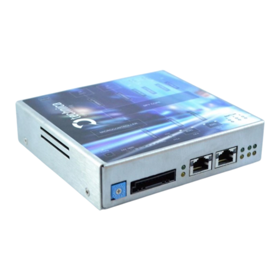
1.1 Functionality and Features of the CM_Eth_Combo Figure 1-1: Capture_Module_Eth_Combo The Technica Engineering Capture Module Eth Combo is used to capture the traffic from 1x 1000BASE-T1 line (between two DUTs) and 2x 100BASE-T1 lines, correspondingly. The traffic is captured without causing interference on the network and delivered with a 40 ns resolution hardware time stamp, thus making the analysis of AVB/TSN traffic possible. - Page 6 Source Timestamping with 40 ns resolution Rotary Switch for manual configuration of the device’s IP-Addresses (Gbit – RJ-45) Wakeup capable Robust stainless-steel case General Information: Power requirement: 8 to 18 Volt DC (nominal 12 Volt DC) Power consumption: 5,5 to 6,6 Watt Size: 137 x 129 x 33 mm Weight:...
-
Page 7: Warranty And Safety Information
Do not place the device near to highly flammable materials due to fire danger. If you wish to discard a CM_CAN_Combo from Technica Engineering GmbH, please contact your dealer or supplier for further information. This symbol is only valid in the European Union. If you wish to discard this product, please contact your local authorities or dealer and ask for the correct method of disposal. -
Page 8: Declaration Of Conformity
1.3 Declaration of Conformity Figure 1-2: Copy of Declaration of conformity 1.4 Scope of Delivery The delivery includes: 1x CM_Eth_Combo Cable-set can be ordered separately. 1x Cable-set o 1m Ethernet Cable, o connectors, o crimp contacts, o cables, CM Eth Combo User Manual... -
Page 9: Different Hardware Versions
o banana plugs 1.5 Different Hardware Versions Two hardware versions must be differentiated: First Second v1.0 - 2.4 (not available anymore) V3.0 and higher Advantages of second version: Better performance due to temperature issue Start up much faster More internal space for buffering. Note: there are different software versions for the different hardware versions available. -
Page 10: Hardware Interfaces
2 HARDWARE INTERFACES 2.1 Connectors On the label on top of the device you can see an overview about all HW-Interfaces of the CM_Eth_Combo. Figure 2-1: Label of CM_Eth_Combo with pinning information CM Eth Combo User Manual... -
Page 11: Power Connector - Black Mqs Connector Frontside (10 Pins One Row)
2.1.1 Power Connector - Black MQS Connector Frontside (10 pins one row) Figure 2-2: Power Connector Power supply for the device is supplied by Pin 1 (12Volt) and Pin 2 (Ground) Requirements for the device itself: 12 Volt DC up to 1 Ampere (typical 600mA). Warning: If you apply a voltage higher than 18 Volt, the device will be damaged! In this connector there are also two wakeup lines: As a digital input, each wake-up line consumes approx. -
Page 12: Rj45 Ethernet Connectors
Function Function Battery +12 Volt Input n.c. Power Ground n.c. WakeUP 1 n.c. WakeUP 2 100 BASE-T1 Plus n.c. 100 BASE-T1 Minus Table 2-2: Pinning of black MQS connector By the 100BASE-T1 port in this connector, you get access to the webserver by the default IP-address (192.168.0.49 if not changed). -
Page 13: Matenet Connectors Backside (2X)
Name Picture Part Number Tyco, MQS Abdeckkappe 2x6 Pol, White 2-967415-1 Tyco, MQS Buchsengehäuse 2x6 Pol, Black 965776-1 Tyco crimp contact 928999-1 Table 2-3: Parts of Tyco MQS Connector Note: You can use the official Tyco tool for these crimp contacts. A cheap variant is the crimp tool for “PSK”... -
Page 14: Usb Mini Connector
Name Picture Part Number Tyco 1-PORT MATENET HDR ASSY 90DEG 9-2304372-9 Tyco MATENET, FEMALE INSERT MODUL, 965776-1 BLACK Tyco Nano MQS crimp contact 1-1703930-2 Table 2-5: Parts of Tyco MATEnet Connector Note: You can use the official Tyco tool for these crimp contacts. Function Function 1000BASE-T1 3A/3B Minus... -
Page 15: Rotary-Switch In Status 0 To D
2.2.1.1 Rotary-Switch in status 0 to D The IP-addresses are not configurable by software or by any user interface and can only be changed by using the rotary switch. It is overtaken after 500ms by a software reset. The current IP-address is shown on the System Information tab. Access to the CM_Eth_Combo is given through the defined configuration port or 100BASE-T1 Port on the Frontside (Host). - Page 16 In the middle (1): LED F: The “FPGA” LED toggles (approx. 2 sec) during normal operation. If it is not blinking or blinking faster, FPGA is damaged and must be repaired LED H: The “Host” LED can toggle at two different speeds: Slow toggle (approx.
-
Page 17: Access By Webserver
3 ACCESS BY WEBSERVER You get access to the Webserver by connecting the device in default via the GB A Port (RJ-45) to your PC. The IP-address of the device is dependent on the status of the Rotary-Switch (see 2.2.1) HAPTER Or you get access to the Webserver by the 100BASE-T1 Port to the Microcontroller and the IP address 192.168.0.49 as default. -
Page 18: Configuration Of The Device
4 CONFIGURATION OF THE DEVICE 4.1 Save Changes If you change anything in the configuration the following hint appears: Figure 4-1: Save Configuration You don’t have to save every time when this hint appears. You can make all wished changes and save the configuration at the end. Please check the box “restart after saving”... -
Page 19: System Information Tab
4.3 System Information tab 4.3.1 General Information Figure 4-3: System Information tab On the “System Information“ tab some status information about the device is displayed. You can check the version number of the application firmware and the bootloader. You see the configured IP-addresses. The version number registers of the switch and PHY chips are displayed for information. -
Page 20: Ip-Addresses
Bootloader version: The current bootloader version of your CM_Eth_Combo is displayed here. Controller IP address: The Current configured IP-address of the 100BASE-T1 port on the Frontside is displayed here. HW-IP address: The current IP-address of the configuration port (RJ-45 Port) is displayed here. -
Page 21: Control Panel Tab
address in the field. After leaving the focus of this field or pressing “Enter” you can save the changes. HW-IP address: This is the current IP-address of the GB-port configured by the Rotary- Switch. It is not configurable except in Rotary-Switch status “E”. For more information please see 2.2.1. -
Page 22: Restart Target
4.4.1 Restart target If you press this button, the CM_Eth_Combo will be restarted. Figure 4-6: Restart device This is useful for discarding not saved changes. 4.4.2 Configuration Figure 4-7: handling of configuration files Change Configuration name: Here you can change the name of the configuration from “Default”... - Page 23 Export Configuration: Applied changes can be exported by pressing the button “Export”. You can choose between these two file-extensions: *.cfg and *.json: Note: Export as *.json-file: If the *.json-file is bigger than the system can handle at once, there will appear more than one download window (the picture is from CM_LIN_Combo, but is the same behavior): Figure 4-8: Download windows Import...
-
Page 24: Prevent Sleep
4.4.3 Prevent sleep Figure 4-9: Prevent standby The CM_Eth_Combo can work in two different operation modes: Prevent sleep: The CM_Eth_Combo works at full capacity and never falls into Sleep-mode. Prevent Sleep: The CM_Eth_Combo works at full capacity as long as there is communication on supervised ports. -
Page 25: Wakeup Lines And Actuator
Note: A hard power reset will not wake up the device from sleep mode if you wait less than 15 seconds. Only the WakeUP lines will wake it up immediately. 4.4.4 WakeUp Lines and Actuator Figure 4-10: WakeUp lines There are two WakeUp Lines. Both WakeUp lines can be input and output. WakeUp Line 1 Actuator: If this box is checked, this wakeup line provides the same voltage as the voltage on the powerline (kind of loop through). -
Page 26: Wup Time To Low
4.4.5 WUP time to LOW Figure 4-11: WUP time to LOW Here you define the time in seconds, which has to go by before the actuator of the wakeup lines is set to ground. The starting point of timecounter is the same time as there is no reason anymore to be awake of the CM_ETH_Combo itself. -
Page 27: Date And Time
4.4.7 Date and Time Figure 4-13: Date and Time By this field you can set the time of the CM_Eth_Combo in shown format for the timestamp in the PLP-protocol. Just type the date and time in the format as follows: YYYY-MM-DDThh:mm:ss After typing please press Note: If no time is set, the time starts from powerup with default value Note: If device is shut down by power reset or fell into status “Sleep”, “Date and... -
Page 28: Switch Status Tab
4.5 Switch Status tab Figure 4-14: Switch Status tab This is an overview of all ports. A blue bar indicates the linkup on this port. If you select a port or any other part of the CM_Eth_Combo, it is shown by blue text of the selected part. -
Page 29: Spy Multiplexer
4.5.1 Spy multiplexer You get access to the SPY multiplexer by clicking on Spy. Here you can set general logging parameters and get an overview of set filters on each port. Figure 4-15: Spy multiplexer Overview (no Filters set) 4.5.1.1 Use PLP header PLP-protocol is activated, and logged data is encapsulated in a new ethernet frame with the original captured ethernet frame as payload. -
Page 30: Keep Original Vlans In Header
Traffic Bandwith is calculated from the overall bandwidth of the input ports, for example: configured traffic bandwidth to 10% means the bit per second will be 100M for 1000Base-T1 and 10M for 100Base-T1 channels. Note: The average input shouldn’t be higher than the maximum bandwidth on the configured logging ports. -
Page 31: Logging Ports For Packetization
4.5.1.7 Logging Ports for packetization Here you define, which port is using packetization. GB-A/B is using packetization GB-A/B is using no packetization Note: Only one port can use packetization at the same time. 4.5.1.8 Delay for Logging By this function it is possible to define, when the CaptureModule starts sending logged data after power on or wakeup (from sleep mode and standby mode) on the configured logging ports. -
Page 32: Filters Table
4.5.1.9 Filters Table Figure 4-16: Overview Filters Table Filters Table shows an overview about the basic filters (in current picture no filter shown). These basic filters can be edited by the button Edit Table. The button Edit Advance Filter opens an editable list of Advance Filter. CM Eth Combo User Manual... -
Page 33: Edit Basic Filter
4.5.1.10 Edit Basic Filter When you press the button Edit Table (F 4-16) you can apply different filters for IGURE the captured data. 4-17 shows the user Interface. IGURE Figure 4-17: Filters Table Close Edit: Leave the Edit screen of Filters Table Clear table: this button deletes all Filter Entries. - Page 34 Figure 4-18: User interface basic filter (Add new entry) Bus: Here can be defined the OABR-Port, to which the filter is applied. “BR 1A” to “BR 2B”, “1000Base-T_A” and “1000Base-T_B”. Parameter to filter: Five different “Parameters to filter” can be set. IN_VLAN: inner VLAN ID OUT_VLAN: outer VLAN ID MAC_SRC: Source MAC Address...
-
Page 35: Edit Advance Filter
4.5.1.11 Edit Advance Filter When you press the button Edit Advance Filter. 4-16) you can apply different IGURE advance filters for the captured data. 4-19 shows the user Interface: IGURE Figure 4-19: User interface advanced filter A maximum of 24 (0-23) rules is possible. CM Eth Combo User Manual... - Page 36 Port: Please select the port, to which the filter will be applied Action: Here you can define, which filter you want to use: Drop: if you want to drop specific frames Mark: specific SPY-flag is set in PLP-header Log without PLP: not available Change BusSpecID: you can change the BusSpecID in PLP...
-
Page 37: Host Port
Field: Here you can define, what you want to filter: Field: no specific value, it must be changed Destination MAC: XX:XX:XX:XX:XX Source MAC: XX:XX:XX:XX:XX Outer VLAN: XXX[hex] Inner VLAN: XXX[hex] Ethernet Type: [2 bytes]: XXXX[hex] IP-Msg Src IPv4: XXX.XXX.XXX.XXX IP-Msg Dest IPv4: XXX.XXX.XXX.XXX Source UDP Port: XXXX[hex]... -
Page 38: Ports
Port name: Port name can be changed here BroadR-Reach® mode: You can change here the Master/Slave Configuration of Host Port Keep Awake Reason Bus: This port is supervised. If on this port is communication, CM_Eth_Combo can’t go asleep. This port is not supervised. The Capture Module can fall asleep even there is communication on this port. - Page 39 Working as Config-port: You can configure the Capture Module by this port with your configuration-PC. The status messages of the Capture Module are transmitted on this port. (for details have a look to the PLP-protocol). Port GB-A is default Config-Port. Port GB- A is also Config-port if no port is configured as Config-port.
-
Page 40: 100Base-T1 Ports
reply of the device connected to the BASE-T1 port (ARP-Target filter and IPv4 Destination filter). Please, activate the function Working as DLT-port, too. For further information please see 4.8. HAPTER 100/1000 BASE-T1 Inputs: This is a table which shows an overview of all BASE-T1- Ports. - Page 41 Keep Awake Reason Bus: This port is supervised. If on this port is communication, CM_Eth_Combo can’t go asleep. This port is not supervised. The Capture Module can fall asleep even there is communication on this port. Section: It is a hexadecimal number. E.G “1A8” It is a number assigned to any port separately.
-
Page 42: 1000Base-T1 Ports
4.5.5 1000BASE-T1 Ports Figure 4-23: 1000BASE-T1 Ports Port name: Port name of every 1000BASE-T1 Port can be changed. Base-T1 mode: You can change here the Master/Slave Configuration of the 1000BASE- T1 Port Port speed: Here you can choose compliance with 1000BASE-T1 and 100BASE-T1 Mode: Here you can choose compliance with IEEE or A0-Phys from Marvel IEEE: IEEE-compliant Legacy: Working in Configuration of A0-Phy from Marvel... - Page 43 Keep Awake Reason Bus: This port is supervised. If on this port is communication, CM_Eth_Combo can’t go asleep. This port is not supervised. The Capture Module can fall asleep even there is communication on this port. Section: It is a hexadecimal number. E.G “1A8” It is a number assigned to any port separately.
-
Page 44: Synchronisation Of Several Devices By Ptp (802.1As)
4.6 Synchronisation of several devices by PTP (802.1AS) 802.1AS is a protocol used between two or more devices to synchronize all of them through an Ethernet communication. This synchronization allows two or more devices (one master and one or multiple slaves) to transmit/receive time-critical information through a physical link and assures that all the devices will handle the same time reference. -
Page 45: Propagation Delay Measurement
“correction field” will be changed and this parameter will be used on reception side to adjust the reference time of the system considering the delay of the switch and the delay in the path „Time-aware system i-1“ to „Time-aware system i“. 4.6.2 Propagation delay measurement For the correction adjust of the time reference transmitted by the Sync and Follow Up... -
Page 46: How To Setup A Synchronized Network With Capturemodules
4.6.3 How to setup a synchronized network with CaptureModules TBD. The available ports for this synchronization are only the GB-Port and the Host port. Note: If there is already one port defined as Bridge-slave there is no more a Bridge- slave-port or 802.1AS Master-port possible. -
Page 47: Inject
Doing: Navigate to rule number by the buttons ➔ press button ➔ press the button ➔ select the Port BR1B ➔ select the action Drop ➔ select the open bracket ➔ choose in Field Outer VLAN ➔ press the button ➔... - Page 48 The GB-A-Port is configured as follows: The important point here is the field IP for Injection. Here must be the IP-Address of the injecting device. Also Working as DLT-port must be activated. Figure 4-28: Example for IP Injection The BR1B-port is configured as follows: Here, the important point is the field IP for Injection.
-
Page 49: Application And Firmware Update
Please follow this update instruction to avoid erroneous states of the device. Technica Engineering may charge support fees for repair service. Only upgrade to the latest firmware. And always bootloader and application Firewall must be deactivated, or Port 69 and Port 9000 must be open You need a stable 12 Volt DC power supply. -
Page 50: Update Via Gb-A Port
5.3 Update via GB-A Port 1. Power up the device. 2. Apply “0” to “D” to the rotary switch and adjust the batch-file for the update to the current set IP-address of the device. 3. Connect a Windows PC with a RJ45 cable directly to the GB-A-Port of the CM_Eth_Combo and make sure there is a link by checking the LEDs blinking. - Page 51 Figure 5-2: Schematic with MediaGateway Figure 5-3: Example of MediaGateway and Capture Module (CM_ETH_Combo) assembly Connect the Ethernet Cable to the Converter or to the MediaGateway 5-5) and IGURE that device to our CM device 5-4). IGURE CM Eth Combo User Manual...
- Page 52 Figure 5-4:Power and BroadR-Reach Connector for Capture Module Figure 5-5: MediaGateway connection in detail Note: It is recommended to use our *.cfg-file for the MediaGateway configuration. With this configuration the Media Gateway forwards the data from the S2-P5 directly to the BR-S2-P0. CM Eth Combo User Manual...
- Page 53 Now you are prepared to run the update: 1. Make sure your networkadapter is configured with correct IP-address 2. Apply “F” to the rotary switch 3. Power up the device. If you Power up the in rotary switch position “F”, the device gets always the default IP 192.168.0.49! 4.
-
Page 54: Additional Information
6 ADDITIONAL INFORMATION • The CM_Eth_Combo is optimized for automotive use. The maximum cable length for 100BASE-T1 segments is limited to 15 meters. • Hardware v2.4 requires at least firmware v003.001.020. CM Eth Combo User Manual... -
Page 55: List Of Figures
7 LIST OF FIGURES Figure 1-1: Capture_Module_Eth_Combo ................. 5 Figure 2-1: Label of CM_Eth_Combo with pinning information ........10 Figure 2-2: Power Connector ................... 11 Figure 2-3: MQS Connectors backside ................12 Figure 2-4: MATEnet Connectors backside ..............13 Figure 2-5: LED allotment on front of the device ............15 Figure 3-1: Home Screen CM_Eth_Combo .............. -
Page 56: Changelog
8 CHANGELOG Version Chapter Description Date 0.991 Draft-Version 12.2019 CM Eth Combo User Manual... -
Page 57: Contact
9 CONTACT If you have any questions regarding this product, please feel free to contact us: Technica Engineering GmbH Leopoldstr. 236 80807 München Germany Technical support: support@technica-engineering.de General information: Info@technica-engineering.de Most current user manuals and product information: https://technica-engineering.de/ CM Eth Combo User Manual...
Need help?
Do you have a question about the IVN2Eth and is the answer not in the manual?
Questions and answers