Table of Contents
Advertisement
Advertisement
Table of Contents

Related Manuals for FibroPool FH-020


Summary of Contents for FibroPool FH-020
- Page 1 Swimming Pool Heat Pump —Operation and Installation Manual— MODEL FH-020...
-
Page 2: Table Of Contents
CONTENTS INTRODUCTION …………………………………........……………………………..…………... Index... …………………………………………………………………………………………………………..The unit ..………………... SAFETY INSTRUCTIONS ………………………………………………………………………… ………………………………………………………………………………………….… 4 Electrical Installation Warning …. ……………………………………………………………………………………………………………… Location Warning CONTENTS OF THE BOX …………………………………………………………………………………………….…… OVERVIEW OF THE UNIT ……………………………………………………………………………………….……… EXPLODED VIEW…………………………………………………………………………………………….…………………. 8 INSTALLATION …………………………………………………………………………………………….…..….…….… 9,10 …………………………………………………………………………………………….…..…..…. Installation AREA ………………………………………………………………………….……………………... -
Page 3: Introduction
INTRODUCTION This manual includes all necessary information about the unit. Please read this manual carefully before you use and maintain pump. The unit The swimming pool heat pump is one of the most economical systems to heat swimming pools efficiently. Using the free, renewable energy from the air, it delivers up to 6.2 times more energy in heating than a traditional heating system such as a gas boiler or electric heater, saving 85% on energy costs. -
Page 4: Safety Instructions
Do not move/repair the unit yourself. Before proceeding with any maintenance, service or repair work, electrical lines must be DISCONNECTED. Only a licensed/competent technician should work on this unit. Use only Genuine FIBROPOOL® PARTS for replacement. All parts can be obtained from Fibropool, www.fibropool.com... -
Page 5: Location Warning
Do not install the unit in a place where there is a fire hazard: GAS LEAKS. If there is a gas leak and gas accumulates in the area surrounding the unit, it could cause an explosion. UNDER THE ROOF EAVES . Although the unit is weatherproof, a direct pour of water from the roof is likely to penetrate the shell and cause a shortage. -
Page 6: Contents Of The Box
CONTENTS OF THE PRODUCT BOX Before starting the installation, please make sure that all parts are found inside the box. The Unit Box Item Image *Swimming pool heat pump **Operation and Installation Manual ***Union set ****Drain adapter elbow ( inside the service panel) -
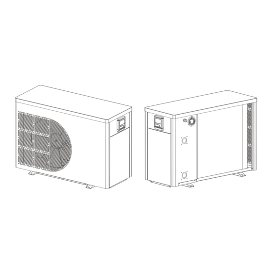
Page 7: Overview Of The Unit
OVERVIEW OF UNIT Unit Dimensions Required Clearance 1'-10” 12”- top A - Height 3'-0” 36” on service panel side, 12” on the far side B - Length 1'-3” 12 “ on both sides C - Width... -
Page 8: Exploded View
EXPLODED VIEW Cover Controller Chassis Fixed frame Fan motor Controller mounting board Front panel Compressor Four way valve Wire controller Evaporator Titanium heat exchanger Copper tube Motor bracket Support column Low pressure switch Left side panel Rear side panel High pressure switch Guide air circle Pressure gauge Copper tube... -
Page 9: Installation
INSTALLATION Installation area Install the unit on a flat, horizontal and stable surface. An HVAC equipment pad is ideal, although 4“ thick concrete blocks will work as well. To optimize installation Allow a minimum of 12” of clearance on all 3 sides, but ensure 36” in front of the service panel Water connection The heat pump can be connected to the filtration circuit by one of two methods: With a 3-valve... -
Page 10: Trial Running
Trial running After connecting water to the pool system perform a test run. Ensure that: Appliance is horizontal and on a firm base. Plumbing is firmly connected, using the approved type of pvc primer, glue or couplings. Electrical wire is firmly connected (all screws tightened correctly at terminals and intermediate circuit breaker), insulated and GROUNDED correctly. -
Page 11: Operating The Unit
OPERATING THE UNIT Operating the unit is done by the controller ONLY. There will be NO NEED to open the service panel for operations NEVER LET THE DIGITAL CONTROLLER GET WET. THIS MAY LEAD TO AN ELECTRICAL SHOCK OR FIRE. NEVER PRESS THE BUTTONS OF THE DIGITAL CONTROLLER WITH A HARD, POINTED OBJECT. -
Page 12: Buttons
Buttons Unit ON/OFF button USE THIS BUTTON TO TURN THE UNIT ON or OFF. Unit is ON when clock, running mode and timing state are displayed on screen. Mode button Press this button to select the running mode at any time. Each time this button is pressed, the HEATER will cycle between one of four modes IF AVAILABLE. -
Page 13: System Fault Table
SELF DIAGNOSTIC SYSTEM CODES AND ERRORS: Protection/ remote LED indicator Malfunction controller Standby Dark Normal operation Bright Lower tank water temp. ☆ PP 1 ● (1 flash 1 dark) sensor failure Upper tank water temp. ☆☆ PP 2 ● (2 flashes 1 dark) sensor failure Evaporator coil temp. -
Page 14: Parameter List
PARAMETER CHECK AND ADUSTMENT Parameter list Some parameters can be checked and adjusted by the controller. Below is the parameter list. Parameter Explanation Range Default Remarks value Cooling water cycle temperature 15-35℃(59~95℉) 82℉(24℃) Adjustable value heating water cycle temperature 15-40℃(59~104℉) 82℉(24℃)... -
Page 15: Maintenance
MAINTENANCE To protect the chassis, avoid placing objects on the device. External heat pump parts can be wiped with a damp cloth and household cleaner. (Note: Never use cleaning agents containing sand, soda, acid or chloride as these can damage the surface) To prevent malfunctions due to sediment in the titanium heat exchanger, ensure that the heat exchanger cannot be contaminated. -
Page 16: Troubleshooting
WHEN CARRYING OUT AN INSPECTION OF THE SWITCH BOX OF THE UNIT, ALWAYS ENSURE THE MAIN SWITCH OF THE UNIT IS SWITCHED ‘OFF’. The guidelines below may help to solve your problem. If you cannot solve the problem, consult your installer or local dealer. 1.877.FIBROPOOL 1.877 342-7676 support@fibropool.com The heat pump will not run. -
Page 17: Environmental Information
ENVIRONMENTAL INFORMATION This equipment contains fluorinated greenhouse gases covered by the Kyoto Protocol. It should only be serviced or dismantled by professional trained personnel. This equipment contains R410A refrigerant in the amount as stated in the specification. Do not vent R410A into the atmosphere: R410A, is a fluorinated greenhouse gas with a Global Warming Potential (GWP) = 1975. -
Page 18: Wiring Diagram
WIRING DIAGRAM Please refer to the wiring diagram on the electric box. MODEL:FH 020...
Need help?
Do you have a question about the FH-020 and is the answer not in the manual?
Questions and answers