
Related Manuals for Curtis G4 Omega Series


Summary of Contents for Curtis G4 Omega Series
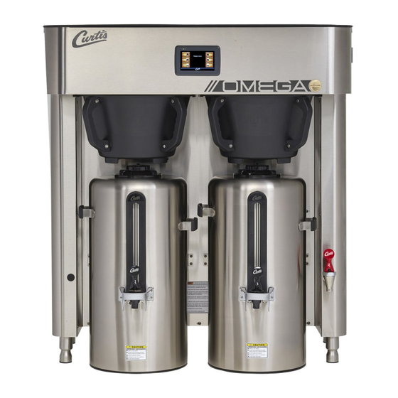
- Page 1 USER GUIDE G4 Omega Series 3.0/6.0 Gallon Coffee Brewing System READ AND SAVE THESE INSTRUCTIONS NOTICE TO INSTALLER: Please leave this booklet with the machine.
-
Page 2: Table Of Contents
...........................ES73 ........................ES74 ........................ES75 ........................................................................................................EC1 ..............................Contact Information Wilbur Curtis Co., Inc. 6913 Acco Street | Montebello, CA 90640 US Phone: 323-837-2300 | Toll Free: 800-421-6150 Email: csrassistance@wilburcurtis.com | Web: www.wilburcurtis.com . - 4:00 . PT Email: techsupport@wilburcurtis.com... -
Page 3: Fs37
KEY FEATURES/SPECIFICATIONS/SYSTEM REQUIREMENTS FS37 Key Features • High Volume Brewing – OMGT/OMGT10 brews 36 gallons of coffee per hour. OMGS brews 25 gallons of coffee per hour • High Volume Tank Capacity – 6.5 gallons (Single), 14.5 gallons (Twin) • High Volume Brew Basket –... -
Page 4: Is2
INSTRUCTIONS could result in personal injury or void the warranty. • This appliance is designed for commercial use. Any service other than cleaning and preventive maintenance should be performed by an authorized Wilbur Curtis service technician. • serviceable parts inside. - Page 5 IMPORTANT SAFEGUARDS CE Requirements • This appliance must be installed in locations where it can be overseen by trained personnel. • • • • This appliance must not be cleaned by water jet. • instruction concerning use of the appliance in a safe way and if they understand the hazards involved. •...
-
Page 6: Ii2
INSTALLATION INSTRUCTIONS WARNING: WARNING: properly grounded. NOTICE: SPECIFICATIONS section. IMPORTANT: Installation Instructions Installation Requirements • A secure surface capable of supporting the weight of the appliance. • For units without an attached cord set: Appropriately sized, UL listed, grounding type power cable to meet enough •... -
Page 7: Ii6
INSTALLATION INSTRUCTIONS Installation Requirements (cont.) • The brewer must maintain a minimum distance of 4 inches from the chassis to the walls on the left, right and back sides (see below). • The brewer must not have anything mounted above it or on top of it. Nothing on top of or above the brewer 4”... - Page 8 INSTALLATION INSTRUCTIONS Installation (cont.) Connect the Brewer Wiring WARNING: Turn off power to the junction box at the with model circuit breaker panel before connecting the power cable to the brewer. Remove the screws that hold the top panel in place and remove.
- Page 9 INSTALLATION INSTRUCTIONS 14 Go to the PROGRAMMING GUIDE section and program the brewer for the correct model and batch number. IMPORTANT: When operating the brewer at higher elevations, reduce the factory set operating temperature (200°F) by 2°F for each 1000 feet of elevation above 4000 feet.
-
Page 10: Oi30
OPERATING INSTRUCTIONS OI30 Brewing Instructions WARNING - TO AVOID SCALDING, AVOID SPLASHING. Keep body parts clear of the brewer during The G4 Omega Brewer is factory preset for optimal performance. Power switch The brewer should be ON. Center an empty dispenser under the brew basket. -
Page 11: Ci13
CLEANING INSTRUCTIONS CI13 WARNING: HOT SURFACES - To avoid injury, allow the brewer and dispenser(s) to cool before cleaning. NOTICE - Do not use cleaning liquids, compounds or powders containing chlorine (bleach) or corrosives. USE OF THESE PRODUCTS WILL VOID THE WARRANTY. -
Page 12: Ci14
CLEANING INSTRUCTIONS CI14 Cleaning the Brew Basket Handles (Weekly) Once a week clean the brew basket handles. Prepare a mild solution of dishwashing detergent and warm water. Remove the two handles from the brew basket. Use a slotted screwdriver to remove the four slotted screws that attach them. -
Page 13: Ci15
CLEANING INSTRUCTIONS CI15 Cleaning the 3.0 Gallon Thermal Dispensers (Daily) WARNING: DO NOT immerse thermal dispensers in water or any other liquid. Do not place the thermal dispensers in a dishwasher. Placing a thermal dispenser in a dishwasher will void the warranty. To avoid damage, DO NOT use a brush to clean the faucet or the inside of the dispenser shank (outlet). - Page 14 Control symbols - all symbols may not be present at the same time Return to Home Undo Curtis logo Scroll left/right previous Entering Programming Mode The ACCESS CODE screen will appear. The menu icons. The icons vary based on the model appear.
- Page 15 PROGRAMMING GUIDE Programming SELECTIONS FOR COFFEE BREWER MODELS Model Select Recipes Control Settings Brew Settings Settings Summary Exit Coffee ® Gemini Gemini IF ™ One Batch GEMX Single Gourmet Std Two Batch TP/TPX Twin Light Roast By Volume/Time Three Batch ™...
- Page 16 PROGRAMMING GUIDE USB - Easy Programming program each step individually using the touchscreen. This process also makes it easy to quickly standardize the IMPORTANT: completely Uploading the Software to the Flash Drive as desired. Downloading the Software to the Brewer from the Flash Drive Select the (identical) brewer you wish to make program changes to.
- Page 17 ROUGH-IN DRAWINGS RD43 Omega - Single Coffee Brewer 21.38 in [54.3 cm] 22.31 in 25.23 in [56.7 cm] 64.1 cm] 23.56 in 59.8 cm] 40.13 in [101.9 cm] 24.42 in [62.0 cm] 9.00 in 8.13 in [22.9 cm] [20.6 cm] 2.00 in 14.69 in [5.1 cm]...
- Page 18 ROUGH-IN DRAWINGS RD43 Omega - Twin Coffee Brewer 36.50 in [92.7 cm] 22.00 in [55.9 cm] 24.67 in [62.6 cm] 23.25 in [59.1 cm] 40.13 in [101.9 cm] 24.25 in [61.6 cm] 9.00 in [22.9 cm] 2.00 in 14.13 in [5.1 cm] [35.9 cm] 23.38 in...
- Page 19 ILLUSTRATED PARTS LIST IP68 Supplies and Accessories - All Models CAB-1 - Cleaning Brush OMGS[16] - Main Chassis - Exploded View Water tank assembly: See section IP70 OMEGA, ILLUSTRATED PARTS/RECOMMENDED PARTS 111617NC...
-
Page 20: Ip68
BRACKET, BREWCONE NOT ROTATE MOLEX CONNECTOR WC-2471 ELBOW, SILICONE OMEGA WC-2402P ELBOW, 3/8”FL x 3/8” NPT PLATE WC-390092 LABEL, FRONT OMEGA CURTIS LOGO WC-588 NOISE, EMI FILTER 250VAC/20A WC-3394 BREW BASKET, WIRE ASSEMBLY OMGT/OMGS WC-14045-101 CURRENT SENSOR ASSY G4 WC-43059 CLAMP, HOSE SNAP NYLON .616/.707... - Page 21 ILLUSTRATED PARTS/RECOMMENDED PARTS IP68 OMGT[10/16/30] - Main Chassis - Exploded View Water tank assemblies - Models OMGT, OMGT16, OMGT30 see section IP71 - Model OMGT10, see section IP72 OMEGA, ILLUSTRATED PARTS/RECOMMENDED PARTS 111617NC...
- Page 22 FUSE HOLDER, CLASS CC 30A 2P FOR WC-1520 WC-14045-101 CURRENT SENSOR ASSY G4 WC-172 1,2,3 SWITCH, 50 AMP ROCKER STYLE OMGT/ OMGS WC-390092 LABEL, FRONT OMEGA CURTIS LOGO SWITCH, TOGGLE NON-LIT SPST 15A 125/6A WC-3394 BREW BASKET, WIRE ASSEMBLY OMGT/OMGS WC-102 4 250VAC RESISTIVE WC-43059 CLAMP, HOSE SNAP NYLON .616/.707...
-
Page 23: Ip70
ILLUSTRATED PARTS LIST IP70 WC-62091 - Tank Assembly WC-62091 - Tank Assembly - Parts List ITEM # PART # DESCRIPTION ITEM # PART # DESCRIPTION WC-62091 TANK, COMPLETE 7.5KW 220VAC OMGS THERMOSTAT, HI LIMIT HEATER CONTROL WC-522 DPST 277V 40A WC-37008 KIT, TANK LID ROUND WC-43055... -
Page 24: Ip71
ILLUSTRATED PARTS LIST IP71 WC-54328 - Tank Assembly WC-54328 - Tank Assembly - Parts List ITEM # PART # DESCRIPTION ITEM # PART # DESCRIPTION WC-54328 TANK, COMPLETE 208V 12KW OMGT WC-37266 KIT, FITTING TANK OVERFLOW WC-61832 LID, TANK ASSY OMGT KIT, STRAIGHT PLASTIC FITTING AND BUSHING WC-37357 12MM... -
Page 25: Ip72
ILLUSTRATED PARTS LIST IP72 WC-54328-102 - Tank Assembly WC-54328-102 - Tank Assembly - Parts List ITEM # PART # DESCRIPTION ITEM # PART # DESCRIPTION WC-54328 TANK, COMPLETE 208V 12KW OMGT WC-37266 KIT, FITTING TANK OVERFLOW WC-61832 LID, TANK ASSY OMGT KIT, STRAIGHT PLASTIC FITTING AND BUSHING WC-37357 12MM... -
Page 26: Es70
ELECTRICAL SCHEMATICS ES70 OMGS OMGS, ELECTRICAL SCHEMATIC 042617NC... -
Page 27: Es71
ELECTRICAL SCHEMATICS ES71 OMGS16 OMGS16, ELECTRICAL SCHEMATIC 042617NC... -
Page 28: Es72
ELECTRICAL SCHEMATICS ES72 OMGT OMGT, ELECTRICAL SCHEMATIC 042617NC... -
Page 29: Es73
ELECTRICAL SCHEMATICS ES73 OMGT10 OMGT10, ELECTRICAL SCHEMATIC 042217NC... -
Page 30: Es74
ELECTRICAL SCHEMATICS ES74 OMGT16 OMGT16, ELECTRICAL SCHEMATIC 042617NC... -
Page 31: Es75
ELECTRICAL SCHEMATICS ES75 OMGT16 OMGT30, ELECTRICAL SCHEMATIC 060517NC... - Page 32 TROUBLESHOOTING GUIDE WARNING: Electric Shock Hazard - Scald and Burn Hazard - IMPORTANT: always check all Valve Test Procedure Troubleshooting Guidelines • • • • Valve Test Procedure in either direction Water Not Hot Enough replace the temperature sensor Water Heats More Slowly Than Usual During Brewing...
- Page 33 TROUBLESHOOTING GUIDE No Power - Display Not Lit Water Tank Does Not Fill Brewer Does Not Start When Brew Button is Pressed Brewing Brewing Sensor Error Message...
- Page 34 TROUBLESHOOTING GUIDE Water Tank Does Not Fill IMPORTANT: Coffee/Tea Too Strong Dispenser Not Filled To Normal Level During Brewing Dispenser Not Filled To Normal Level During Brewing sure that the spray head is correctly aligned and that the tubing is routed properly to allow for maximum water All Of The Time...
- Page 35 TROUBLESHOOTING GUIDE No Water/Tea Flows From Brewer During Brewing Water Tank Does Not Fill Low Water Flow Warning Water Level Error Message Water Level Error Message “Internal Error 1” Message on Display “Internal Error 2” Message on Display PROGRAMMING GUIDE...
- Page 36 TROUBLESHOOTING GUIDE Water Does Not Heat At All Check to see if the water level in the tank is in contact with the water level probe. If not, see Tank Does Not Fill. • The water will not heat unless it is in contact with the probe. If the water heats, but is not hot enough, see Water Not Hot Enough.
- Page 37 The G4 control module diagnostics can be used to detect electrical circuit failures in the brewer. When a circuit Using the Diagnostics The MAIN MENU Control Settings. Diagnostics Curtis logo Auto Test to test all circuits. If a button is highlighted green the DIAGNOSTICS Left Auto Test...
-
Page 38: Ec1
ERROR CODES Warning Messages - Allows Brewer to Continue Brewing MESSAGE DISPLAY WARNING DESCRIPTION CAUSE Brew count “Gallons Since Reset” exceeds programmed Maintenance Required Maintenance Required preventative maintenance period. If the Inlet valve remains on longer than XX seconds (during the brew cycle only) and repeats TWICE during that brew cycle. - Page 39 Return Merchandise Authorization (RMA): All returned equipment must be properly re-packaged in the original carton and received by Curtis within 45 days following the issuance of a RMA. NO UNITS OR PARTS WILL BE ACCEPTED WITHOUT A RETURN MERCHANDISE AUTHORIZATION (RMA).
Need help?
Do you have a question about the G4 Omega Series and is the answer not in the manual?
Questions and answers