Sign In
Upload
Download
Table of Contents
Contents
Add to my manuals
Delete from my manuals
Share
URL of this page:
HTML Link:
Bookmark this page
Add
Manual will be automatically added to "My Manuals"
Print this page
×
Bookmark added
×
Added to my manuals
Manuals
Brands
Curtis Manuals
Coffee Maker
G4 Omega Series
User manual
Curtis G4 Omega Series User Manual
3.0/6.0 gallon coffee brewing system
Hide thumbs
Also See for G4 Omega Series
:
Instructions manual
(39 pages)
1
Table Of Contents
2
3
4
5
6
7
8
9
10
11
12
13
14
15
16
17
18
19
20
21
22
23
24
25
26
27
28
29
30
31
32
33
34
35
36
37
38
39
40
41
42
43
page
of
43
Go
/
43
Contents
Table of Contents
Bookmarks
Table of Contents
Table of Contents
Fs37
Is2
Ii2
Ii6
Oi30
Ci13
Ci14
Ci15
Ip68
Ip70
Ip71
Ip72
Es70
Es71
Es72
Es73
Es74
Es75
Ec1
Advertisement
Quick Links
Download this manual
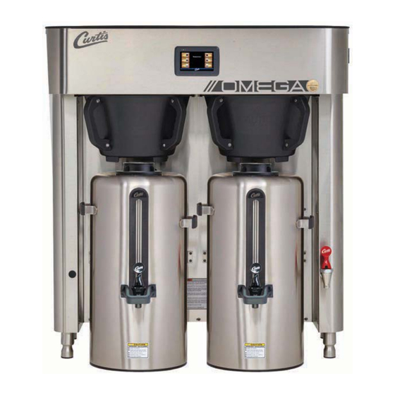
USER GUIDE
G4 Omega Series 3.0/6.0 Gallon
Coffee Brewing System
READ AND SAVE THESE INSTRUCTIONS
NOTICE TO INSTALLER: Please leave this booklet with the machine.
D
Table of
Contents
Previous
Page
Next
Page
1
2
3
4
5
Advertisement
Table of Contents
Need help?
Do you have a question about the G4 Omega Series and is the answer not in the manual?
Ask a question
Questions and answers
Related Manuals for Curtis G4 Omega Series
Brewing Systems Curtis G4 Omega Series Instructions Manual
3.0/6.0 gallon coffee brewing system (39 pages)
Coffee Maker Curtis OMGS 3PH Service Manual
(19 pages)
Coffee Maker Curtis G4 Gemini Twin Service Manual
(12 pages)
Coffee Maker Curtis G4GEMT Service Manual
G4 gemini twin coffee brewer (12 pages)
Coffee Maker Curtis G4GEMS Service Manual
G4 gem single head brewer (18 pages)
Coffee Maker Curtis G4GEMTIF Service Manual
G4 gemini intellifresh twin brewer (17 pages)
Coffee Maker Curtis ThermoPro G4 Service Manual
Twin brewer (12 pages)
Coffee Maker Curtis G4 CGC Series User Manual
Digital coffee brewing system (32 pages)
Coffee Maker Curtis G4TPX1S63A3100 User Manual
Coffee brewing system (40 pages)
Coffee Maker Curtis G4 TPX2 User Manual
1.5 gallon coffee brewing system (37 pages)
Coffee Maker Curtis G4TP1S63A3100 User Manual
1 gallon coffee brewing system (36 pages)
Coffee Maker Curtis IntelliFresh G4 GEMX User Manual
(54 pages)
Coffee Maker Curtis G4 ThermoPro Series User Manual
1 gallon coffee brewing system (37 pages)
Coffee Maker Curtis IntelliFresh G4GEMXN User Manual
Coffee brewing system (39 pages)
Coffee Maker Curtis G4 ThermoProX User Manual
(54 pages)
Coffee Maker Curtis G4 GEMX IntelliFresh G4GEMXSIFTR10A3026 User Manual
Coffee brewing system with dispenser detection (42 pages)
This manual is also suitable for:
Omgs
Omgs16
Omgs38
Omgt
Omgt10
Omgt16
...
Show all
Omgt30
Table of Contents
Print
Rename the bookmark
Delete bookmark?
Delete from my manuals?
Login
Sign In
OR
Sign in with Facebook
Sign in with Google
Upload manual
Upload from disk
Upload from URL


Need help?
Do you have a question about the G4 Omega Series and is the answer not in the manual?
Questions and answers