Table of Contents
Advertisement
Quick Links
Advertisement
Table of Contents
Troubleshooting

Related Manuals for Froling S3 Turbo 30


Summary of Contents for Froling S3 Turbo 30
- Page 1 Owner´s Manual S3 Turbo Read and follow the operating instructions and safety information! Subject to technical change! Froling Heizkessel- und Behälterbau Ges.m.b.H, Industriestraße 12, A-4710 Grieskirchen Tel +43 (0) 7248 606-0 Fax +43 (0) 7248 606-600 info@froeling.com www.froeling.com...
-
Page 2: Table Of Contents
Risks from flue gases, lubricants and other equipment What to do in the case of danger Staff requirements Personal protective equipment Replacement parts 2.10 Environmental protection 2.11 The operator's responsibilities Description of the boiler Front view Froling GesmbH | A-4710 Grieskirchen, Industriestraße 12 | www.froeling.com... - Page 3 Table of Contents Back view Cross-section Functional description Permitted fuels Non-permitted fuels Transport, Installation und Initial start-up Safety Conditions for initial start-up Heating the boiler Safety instructions for heating Operation via the boiler controller 5.2.1 Control keys and display Navigation keys Status LED Graphic display Function keys...
-
Page 4: Froling Gesmbh | A-4710 Grieskirchen, Industriestraße 12 | Www.froeling.com
Table of Contents Boiler faults Safety instructions for troubleshooting Troubleshooting table 7.2.1 Reset the high-limit thermostat. After troubleshooting Dismantling and disposal Technology Dimensions Components and connections Technical data Froling GesmbH | A-4710 Grieskirchen, Industriestraße 12 | www.froeling.com... - Page 5 Supplementary instructions Supplementary instructions These instructions ensure safe and efficient use of the S3 Turbo (hereinafter referred to as the “system"). These instructions are a component part of the system and must be kept next to the system and within the immediate reach of staff at all times. Staff must carefully read and understand these instructions before commencing all work.
-
Page 6: Overview
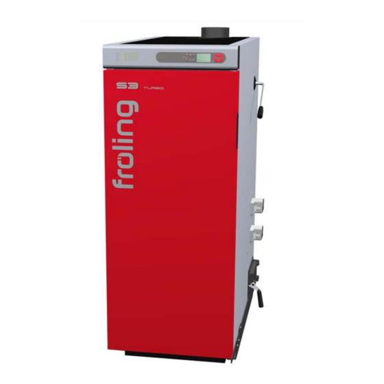
Overview Front view 1 Overview 1.1 Front view Boiler S3 Turbo Boiler controller control panel WOS lever Actuator of primary air flap Actuator of secondary air flap Heat exchanger cleaning door Froling GesmbH | A-4710 Grieskirchen, Industriestraße 12 | www.froeling.com... -
Page 7: Back View
Overview Back view 1.2 Back view Boiler flow connection Induced draft fan Thermal discharge safety device connection Drainage Boiler return connection Owner´s Manual S3 Turbo | B1390016_en-us... -
Page 8: Cross-Section
Insulated door Fuel-loading chamber door Pre-heating chamber door Combustion chamber door Fuel-loading chamber Combustion chamber Heat exchanger with spiral springs In flue gas nozzle: Flue gas temperature sensor and broadband lambda probe Froling GesmbH | A-4710 Grieskirchen, Industriestraße 12 | www.froeling.com... -
Page 9: Boiler Manufacture And Testing
Boiler manufacture and testing 1.4 Boiler manufacture and testing Your boiler was manufactured by Froling, a world leader on hot water (hydronic) heat‐ ing for over 50 years. The S3 Turbo boiler confirms to traditional high standards for quality and reliability. It offers modern fire wood boiler technology with operating effi‐... -
Page 10: Safety
Special safety information The following symbols are used to draw your attention to particular hazards Tips and recommendations Italics indicate useful tips and recommendations as well as information for efficient and smooth running. Froling GesmbH | A-4710 Grieskirchen, Industriestraße 12 | www.froeling.com... -
Page 11: Permitted Uses
Safety Permitted Uses Other markers The following markers are used in these instructions to highlight operating guidelines, results, lists, references, and other elements: Marker Explanation ❒ Step-by-step operating instructions ➥ Results of actions Lists without a specified order ▪ [Button] Operating elements (e.g. - Page 12 ROSION DURING THE SUMMER MONTHS. THE APPLIANCE, FLUE PIPE, AND CHIMNEY MUST BE IN GOOD CONDITION. THESE INSTRUCTIONS AL‐ SO APPLY TO A DRAFT INDUCER IF USED. ➥ Misuse of the boiler can create hazardous situations. Froling GesmbH | A-4710 Grieskirchen, Industriestraße 12 | www.froeling.com...
-
Page 13: Requirements At The Place Of Installation
Safety Requirements at the place of installation 2.3 Requirements at the place of installation 2.3.1 Approval for the heating system The appropriate supervisory authority (inspection agency) must always be informed when installing or modifying a heating system, and authorization must be obtained from the building authorities. -
Page 14: Requirements For Central Heating Water
You can add anti-freeze to the heating water, however, this can reduce the heating ef‐ ficiency. Always follow the manufacturer’s dosing instructions when using anti-freeze, as using the incorrect amount can cause corrosion. Check the concentration of the an‐ ti-freeze at regular intervals. Froling GesmbH | A-4710 Grieskirchen, Industriestraße 12 | www.froeling.com... -
Page 15: Ventilation Requirement For Boiler Room
Safety Requirements at the place of installation 2.3.4 Ventilation requirement for boiler room Introduction The external combustion air must meet certain requirements to ensure that adequate combustion air is supplied to the boiler and no by-products from the combustion get into the boiler room. -
Page 16: Combination With Thermal Storage
If the outside temperature is low, condensation water can freeze at the chimney outlet, which can result in inade‐ quate chimney escape, limited boiler output and a system breakdown. Froling GesmbH | A-4710 Grieskirchen, Industriestraße 12 | www.froeling.com... -
Page 17: Requirements For The Chimney Connection
Safety Requirements at the place of installation 2.3.9 Requirements for the chimney connection The chimney connection must be big enough to channel flue gases from the building. The whole flue gas system must be designed to prevent possible seepage, insufficient feed pressure and condensation. -
Page 18: Safety Markers
Securing the main switch Switch off the main switch and secure with a padlock when carrying out maintenance work to the boiler. Froling GesmbH | A-4710 Grieskirchen, Industriestraße 12 | www.froeling.com... -
Page 19: Prohibitions
Safety Safety markers 2.4.2 Prohibitions Unauthorized access prohibited Only persons authorized by the operator may enter the danger zone and fuel storage room. Keep children away! Keep the fuel storage room locked and keep the access key in a safe place. Protect the fuel from moisture. No fire, open flames or smoking Areas marked with this are at risk of fire or explosion. -
Page 20: Signage On The Boiler
This boiler is not for use with an automatic stoker Connection to an existing boiler system in combination with heat storage only! Use original spare parts only. Installation of non-licensed replacement parts will void the warranty! A 851 01 16 Froling GesmbH | A-4710 Grieskirchen, Industriestraße 12 | www.froeling.com... -
Page 21: Notice Of Risks During Operation
Safety Safety markers Notice of risks during operation S3 Turbo - WOOD FIRED GASIFICATION HYDRONIC FURNACE OPERATION HAZARDS NOTICE! Burn Wood only, max. length 21'' (51cm)! Load fuel carefully or damage will result! Build the wood fire directly on the boiler Fuel Loading Chamber refractory floor! Do not use small pieces or wood waste that could fall through the center slot in the refractory. -
Page 22: Notice Regarding Procedures In An Emergency
- When boiler temperature has dropped below 180°F (82°C), reverse the above steps. - In case Safety Temperature Limit Switch automatically has been activated please refer to Owner’s Manual. A 853 01 16 Froling GesmbH | A-4710 Grieskirchen, Industriestraße 12 | www.froeling.com... -
Page 23: Residual Risks
Safety Residual risks 2.5 Residual risks 2.5.1 Basic risks Incorrect operation Risk of injury from operating the system incorrectly! WARNING ❒ Modifications to the boiler controller must only be undertaken in consultation with the manufacturer. ➥ Modifying parameters on the boiler controller can cause malfunctions. 2.5.2 Risks from electricity Electric current Risk of death from electrocution! -
Page 24: Danger From Fire And Explosion
➥ If, in the event of a fire, the fire extinguisher is not fit for use or unsuitable for the specific fire class, this can result in serious injuries or even death and sig‐ nificant damage to property. Froling GesmbH | A-4710 Grieskirchen, Industriestraße 12 | www.froeling.com... -
Page 25: Danger From High Temperatures
Safety Residual risks Flue gas system Risk of injury and damage to property from obstructing the flue gas system! WARNING ❒ The chimney is only to be used as an outlet for one heating system. ❒ Optimum performance can only be guaranteed if the flue gas system is function‐ ing correctly. -
Page 26: Risks From Flue Gases, Lubricants And Other Equipment
➥ Dust deposits could catch fire or form an explosive compound if dispersed with the ambient air. This can result in serious and even fatal injuries. Froling GesmbH | A-4710 Grieskirchen, Industriestraße 12 | www.froeling.com... -
Page 27: What To Do In The Case Of Danger
If the system overheats, proceed as follows: ❒ Keep all the doors on the boiler closed. ❒ Open all mixing valves; switch on all pumps. The Froling heating circuit control takes on this function in automatic operation. ❒ Leave the boiler room and close the access door. -
Page 28: Staff Requirements
Froling customer service or an authorized partner The Froling customer service or its authorized partner is able to perform the tasks as‐ signed to it and recognize and avoid possible dangers thanks to its professional, prod‐ uct-related training, knowledge and experience as well as its knowledge of the rele‐... - Page 29 Safety Staff requirements Licensed electrician Thanks to his training, knowledge, experiences and knowledge of relevant standards and provisions the licensed electrician is capable of performing the following tasks on electrical systems professionally and according to safety requirements: ❒ Planning and connecting electrical systems based on circuit and current flow dia‐ grams ❒...
-
Page 30: Personal Protective Equipment
Danger of injury when using incorrect replacement parts! WARNING ❒ Use only original Froling replacement parts or spare parts approved by Froling. ❒ In case of doubt, always contact our customer service. ➥ Hazards for the staff can arise through the use of incorrect or faulty spare parts and cause damage, malfunction or total failure. -
Page 31: Environmental Protection
Safety Environmental protection 2.10 Environmental protection Danger to the environment resulting from incorrect handling of environmentally haz‐ NOTICE ardous substances! ❒ Always follow the instructions below when handling hazardous substances and their disposal. ❒ If hazardous substances are accidentally released into the environment, take ap‐ propriate measures immediately. - Page 32 ▪ The operator must ensure that the maintenance intervals described in these in‐ structions are respected. ▪ The operator must ensure that the safety devices are regularly checked for proper functioning and completeness. Froling GesmbH | A-4710 Grieskirchen, Industriestraße 12 | www.froeling.com...
-
Page 33: Description Of The Boiler
Description of the boiler Front view 3 Description of the boiler 3.1 Front view Boiler S3 Turbo Boiler controller control panel WOS lever Actuator of primary air flap Actuator of secondary air flap Heat exchanger cleaning door Owner´s Manual S3 Turbo | B1390016_en-us... -
Page 34: Back View
Description of the boiler Back view 3.2 Back view Boiler flow connection Induced draft fan Thermal discharge safety device connection Drainage Boiler return connection Froling GesmbH | A-4710 Grieskirchen, Industriestraße 12 | www.froeling.com... -
Page 35: Cross-Section
Description of the boiler Cross-section 3.3 Cross-section Insulated door Fuel-loading chamber door Pre-heating chamber door Combustion chamber door Fuel-loading chamber Combustion chamber Heat exchanger with spiral springs In flue gas nozzle: Flue gas temperature sensor and broadband lambda probe Owner´s Manual S3 Turbo | B1390016_en-us... -
Page 36: Functional Description
The ashes should be retained in the closed container until all cinders have thoroughly cooled. Froling GesmbH | A-4710 Grieskirchen, Industriestraße 12 | www.froeling.com... - Page 37 Description of the boiler Functional description The heat exchange tubes in the boiler will accumulate fly ash on their inner surface resulting in lowered boiler efficiency. These tubes should be cleaned daily by moving the tube cleaning lever on the side of the boiler back and forth several times. Ash should be removed as needed from the area below the heat exchange tubes via the small ash door.
-
Page 38: Permitted Fuels
Keep away from boiler while it is in operation! ❒ Do not use chemicals, gasoline, gasoline-type lantern fuel, kerosene, charcoal lighter fuel or similar liquids, or any other combustible fluids to start or rekindle the fire in this boiler. Froling GesmbH | A-4710 Grieskirchen, Industriestraße 12 | www.froeling.com... -
Page 39: Transport, Installation Und Initial Start-Up
Take the following precautions: ❒ Initial startup should be carried out with an authorized installer or with Froling cus‐ tomer services. The customer is responsible for ensuring the following prior to initial start-up of the system by Froling customer services or an authorized partner: ▪... -
Page 40: Heating The Boiler
This wood heater has a manufacturer-set minimum low burn rate that must not be al‐ WARNING tered. It is against federal regulations to alter this setting or otherwise this wood heat‐ er in a manner inconsistent with operating instructions in this manual. Froling GesmbH | A-4710 Grieskirchen, Industriestraße 12 | www.froeling.com... -
Page 41: Operation Via The Boiler Controller
Heating the boiler Operation via the boiler controller 5.2 Operation via the boiler controller 5.2.1 Control keys and display Navigation keys Navigation keys are used to move within the menu and to change parameter values. Function used for Navigation: move up a menu level Parameter change: Depending on how long the key is pressed: - Short: increases value... -
Page 42: Graphic Display
Shown when the DHW tank or return temperature control pump is active. Shown when the heating circuit or storage tank loading pump is ac‐ tive. Shows the status of the heating circuit mixer. Froling GesmbH | A-4710 Grieskirchen, Industriestraße 12 | www.froeling.com... -
Page 43: Function Keys
Heating the boiler Operation via the boiler controller Function keys The function keys of the S-Tronic Lambda have dual assignments. Short or long pressing of the keys can access different functions (see below): short keystroke …….. < 1 sec long keystroke …….. > 4 sec Standby key Keystroke Function... - Page 44 The function is indicated by the sun symbol Extraheating started in the status line. Caution: The external temperature heating limit set in the "Heating" menu is active and can prevent re‐ lease of the heating circuits. Froling GesmbH | A-4710 Grieskirchen, Industriestraße 12 | www.froeling.com...
-
Page 45: Setting Parameters
Heating the boiler Operation via the boiler controller Setback program key Keystroke Function shor To activate setback mode on the room console. Heating 08:02 Caution: Function only possible on the room con‐ Setback MODE is not possible in boiler display! sole! After an optional change to the setback tempera‐... -
Page 46: Before Heating Up The Boiler
100% charge status = 185 °F (85 °C) – 7 °F (4 °C) = 178 °F ( 81°C) When the insulated door is opened the boiler display shows the required fuel quantity to load the thermal storage to 100%. Values are shown in SI units. Conversion tables Froling GesmbH | A-4710 Grieskirchen, Industriestraße 12 | www.froeling.com... - Page 47 Heating the boiler Before heating up the boiler Calculation To calculate the energy required we use the formula Q = m x c x Δt. Q = energy required m = mass of the medium to be heated c = heat capacity of the medium to be heated (constant for water) Δt = temperature difference between start and end temperature The amount of fuel can be calculated from the energy required and the energy content of the fuel.
-
Page 48: Fuel Table
❒ If too much fuel is added, the boiler will drop below its minimum output limit and enter into the “Slumber” operating status (blower fan is switched off) ➥ During “Slumber”, the efficiency drops, emissions increase and tar may form in the boiler. Froling GesmbH | A-4710 Grieskirchen, Industriestraße 12 | www.froeling.com... -
Page 49: Heating Up The Boiler
(boiler water, combustion chamber) is not taken into consideration. ❒ Prepare the fuel quantity according to what is shown on the display. Fill level Weight at fill level S3 Turbo 30 S3 Turbo 50 Soft wood approx. 53 lbs (24 kg) approx. 86 lbs (39 kg) Hardwood approx. - Page 50 ❒ Add start-up fuel so that the amount is approximately 10% of the weight of the ex‐ pected firewood load; in other words, if you expect to load 100 pounds of firewood into the boiler, use ten pounds of start-up fuel. Froling GesmbH | A-4710 Grieskirchen, Industriestraße 12 | www.froeling.com...
- Page 51 Heating the boiler Heating up the boiler ❒ Once the kindling and start-up fuel is in place, add the amount of firewood re‐ quired to recharge your thermal storage. ❒ Close the fuel loading door and open the pre-heating chamber door. ❒...
- Page 52 ❒ If the flue gas temperature has reached a value of > 130°C (> 266°F), close the pre-heating chamber door and insulated door. NOTICE! Remain with the boiler during the entire lighting process! Froling GesmbH | A-4710 Grieskirchen, Industriestraße 12 | www.froeling.com...
-
Page 53: Add More Firewood During The Operation
Heating the boiler Add more firewood during the operation 5.5 Add more firewood during the operation When touching hot surfaces behind the insulated door: WARNING Hot surfaces can cause serious burns! By the nature of its operation, the surfaces and operating elements in the area behind the insulated door get hot! There is also a risk of injury from splinters when working with firewood. - Page 54 ➥ A firebed is “basic” when it reaches the top row of holes in the cladding. ❒ Open the fuel loading door, add the prepared fuel quantity, then close the fuel loading door and insulated door again. Froling GesmbH | A-4710 Grieskirchen, Industriestraße 12 | www.froeling.com...
-
Page 55: Remove Ash
Heating the boiler Remove ash 5.6 Remove ash ❒ Open the insulated door, pre-heating chamber door and the fuel loading chamber door ❒ Scrape the ash from the fuel loading chamber into the combustion chamber using the furnace tool. ➥ Ash should remain in the boiler up to the height between the lowest and middle rows of holes, about 3”... - Page 56 ❒ Clean the passage to the left and right of the combustion chamber with small brush and remove ash ❒ Shovel the ash into the container provided ➥ Fire-proof container with cover! ❒ Close all boiler doors again after removing the ash. Froling GesmbH | A-4710 Grieskirchen, Industriestraße 12 | www.froeling.com...
-
Page 57: Maintaining The Boiler
❒ Pay attention to order and cleanliness in the boiler room. ❒ Any maintenance work not permitted for the operator must be carried out exclu‐ sively by Froling customer service or an authorized partner. ❒ Always wear personal protective equipment for work (protective clothing, safety shoes, protective gloves). -
Page 58: Securing The System So That It Cannot Be Switched On Again
Cleaning the induced draft fan Froling customer service or an author‐ ized partner Clean the flue gas pipe and check the Chimney sweep chimney draft Checking the draft controller flap Chimney sweep Froling GesmbH | A-4710 Grieskirchen, Industriestraße 12 | www.froeling.com... -
Page 59: Maintenance Work
Maintaining the boiler Maintenance work 6.4 Maintenance work 6.4.1 Checking the safety equipment Checking the system pressure ❒ Check the system pressure on the pressure gauge. ➥ The value must be 20% greater than the preload pressure of the expansion tank. -
Page 60: Remove Ash
❒ Scrape the ash from the fuel loading chamber into the combustion chamber using the furnace tool. ❒ Open the combustion chamber door and remove ash with a round ash shovel ➥ Fire-proof container with cover. Froling GesmbH | A-4710 Grieskirchen, Industriestraße 12 | www.froeling.com... - Page 61 Maintaining the boiler Maintenance work ❒ Remove ash in the area in front of the combustion chamber with the furnace tool. ➥ Fire-proof container with cover. ❒ Clean the passage to the left and right of the combustion chamber with small brush and remove ash ❒...
-
Page 62: Cleaning The Grate
❒ Check the secondary air inlets and clean with an ash vacuum if necessary. ❒ Place the two halves of the grating back on the combustion chamber. ➥ Ensure that they are positioned correctly. ❒ Close all boiler doors after positioning the grating halves. Froling GesmbH | A-4710 Grieskirchen, Industriestraße 12 | www.froeling.com... -
Page 63: Cleaning The Flue Gas Temperature Sensor
Maintaining the boiler Maintenance work 6.4.4 Cleaning the flue gas temperature sensor ❒ Remove the back insulating cover and thermal insulation. ❒ Release the retaining screw and remove the flue gas temperature sensor from the flue gas pipe. ❒ Wipe the flue gas temperature sensor with a clean cloth. ❒... -
Page 64: Cleaning The Primary Air Openings
❒ Unhinge all aprons and remove from the fuel-loading chamber. ❒ Check the primary air openings (left and right) for unobstructed air flow and clean with a screwdriver if necessary. Froling GesmbH | A-4710 Grieskirchen, Industriestraße 12 | www.froeling.com... -
Page 65: Set And Check The Seal On The Doors
Maintaining the boiler Maintenance work ❒ Scrape off all the boiler walls behind the aprons with the furnace tool. ❒ After the primary air openings have been cleaned and the boiler walls scraped off, mount all aprons back in their previous position and close all the boiler doors. 6.4.7 Set and check the seal on the doors The example below shows how to set and check the seals on the fuel loading doors. - Page 66 Setting OK ➥ If the door cannot be closed with the usual force or must be forced closed: Push the locking plate toward the front ⇨ See "Adjusting the doors" [page 67] Froling GesmbH | A-4710 Grieskirchen, Industriestraße 12 | www.froeling.com...
-
Page 67: Adjusting The Doors
Maintaining the boiler Maintenance work Checking the seal: ❒ Open the door ❒ Insert a sheet of paper at both the top and the bottom area at the side of the door handle between the door and the boiler ❒ Close the door ❒... -
Page 68: Cleaning The Heat Exchanger Pipes
❒ Remove the ash above the pipes with an ash vacuum and the ash build-up in the pipes using the cleaning brush ➥ The cleaning brush must be pushed all the way through before pulling it up ➥ The bristles cannot be turned in the pipe Froling GesmbH | A-4710 Grieskirchen, Industriestraße 12 | www.froeling.com... - Page 69 Maintaining the boiler Maintenance work ❒ Hang the WOS turbolators on the linking plate of the stay tube ➥ Make sure that you fit the turbolators in the right position: ➥ Hold the linking plate with the edge toward the top ➥...
-
Page 70: Cleaning The Induced Draft Fan
❒ Remove dirt and deposits from the induced draft housing using a scraper ❒ Remove any ash which has gathered using an ash vacuum ❒ Fit the ID fan and the ID fan cover plates Froling GesmbH | A-4710 Grieskirchen, Industriestraße 12 | www.froeling.com... -
Page 71: Disposing Of Ash
Maintaining the boiler Maintenance work 6.4.10 Disposing of ash Staff: ❒ Operator Protective ❒ Protective workwear equipment: ❒ Protective goggles ❒ Protective gloves ❒ Safety shoes ❒ Dust mask Environmental damage due to improper disposal! NOTICE ❒ Collect ash in a metal container with a tight-fitting cover until its final disposal. ❒... -
Page 72: After Maintenance
❒ Clean the work area and remove any substances that may have leaked such as liquids, processing materials or similar. ❒ Make sure that all safety devices on the system are functioning properly. Froling GesmbH | A-4710 Grieskirchen, Industriestraße 12 | www.froeling.com... -
Page 73: Boiler Faults
❒ Do not acknowledge the fault until it is eliminated or its cause is resolved. ❒ In case of doubt contact Froling customer service. ❒ Before starting up again, please note the following: ➥... -
Page 74: Reset The High-Limit Thermostat
❒ Acknowledge the fault message at the boiler controller. ❒ Make sure that there is no one in the danger zone. ❒ Start the boiler according to the instructions in the “Heating the boiler” section. Froling GesmbH | A-4710 Grieskirchen, Industriestraße 12 | www.froeling.com... -
Page 75: Dismantling And Disposal
Dismantling and disposal 8 Dismantling and disposal Dismantling is carried out exclusively by the manufacturer or by staff authorized by the manufacturer. Risk of death from improper dismantling! WARNING ❒ Dismantling must be carried out exclusively by employees of the manufacturer or staff authorized by the manufacturer. -
Page 76: Technology
Height of flow connection 1280 1380 50 ½ 54 ⅓ Height of return connection 5 ½ 5 ½ Height of safety battery connection 38 ¼ Height of drainage connection 4 ¾ 4 ¾ Froling GesmbH | A-4710 Grieskirchen, Industriestraße 12 | www.froeling.com... -
Page 77: Components And Connections
Technology Components and connections 9.2 Components and connections Pos. Name Unit S3 Turbo Boiler flow connection inches Boiler return connection inches Drainage connection inches Safety battery connection inches Immersion sleeve for thermal discharge valve (sup‐ inches plied by the customer) Immersion sleeve for boiler sensor and STL inches Flue gas pipe connection... -
Page 78: Technical Data
– soft wood 2.8 - 3.9 2.7 - 4.0 1. Values specified for combustion time are guideline values at nominal load and will vary depending on water content (15-25%) and fill level (80-100%) Froling GesmbH | A-4710 Grieskirchen, Industriestraße 12 | www.froeling.com...
Need help?
Do you have a question about the S3 Turbo 30 and is the answer not in the manual?
Questions and answers