Table of Contents
Advertisement
Quick Links
Advertisement
Table of Contents

Related Manuals for Froling S4 Turbo 15


Summary of Contents for Froling S4 Turbo 15
-
Page 1: Assembly Instructions
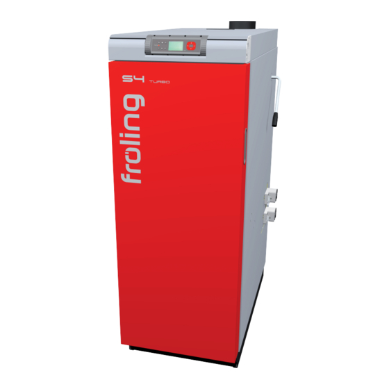
Assembly Instructions S4 Turbo Read and follow the assembly instructions and safety information. Subject to technical change. Fröling Heizkessel- und Behälterbau Ges.m.b.H, Industriestrasse 12, A-4710 Grieskirchen Tel +43 (0) 7248 606-0 Fax +43 (0) 7248 606-600 info@froeling.com www.froeling.com... -
Page 3: Guarantee Conditions
Introduction Dear customer, The FRÖLING S4 Turbo is a state-of-the-art design that conforms to all currently applicable standards and testing guidelines. Please read and follow the assembly instructions. They contain safety instructions and comprehensive information relating to transporting, setting up and assembling the boiler. The continuous development of our products means that there may be minor differences between the illustrations and other content of the document. -
Page 4: Table Of Contents
Boiler data relating to design of the flue gas system.......... 10 2 Technology 2.1 Components and connections 2.2 Dimensions 2.3 Performance data 2.3.1 S4 Turbo 15/22/28 ..................13 Test report data ................... 13 2.3.2 S4 Turbo 34/40 .................... 14 Test report data ................... 14 2.3.3 S4 Turbo 50/60 .................... 15 Test report data ................... - Page 5 Contents 3.5.6 Installing the actuators .................. 29 3.5.7 Installing the Lambda probe ................30 3.5.8 Installing the flue gas sensor ................31 3.5.9 Installing the control unit ................31 3.5.10 Installing the WOS lever................. 32 3.5.11 Install the insulating door ................34 3.5.12 Installing the insulating cover .................
-
Page 6: General Information
General Standards, Design, Assembly 1 General information CAUTION Assembly and installation by untrained personnel. Risk of personal injury and damage to property. The instructions and information provided in the manual must be observed. Assembly and installation must only be carried out by qualified personnel (heating installers or licensed electricians). -
Page 7: Design Information
General Standards, Design, Assembly 1.2 Design Information It is forbidden to carry out modifications to the boiler or to change or deactivate safety equipment. Always comply with all fire, building, and electrical regulations when installing or operating the boiler system, in addition to following the operating instructions and mandatory regulations that apply in the country in which the boiler is operated. -
Page 8: Ventilation Of Boiler Room
General Standards, Design, Assembly 1.2.3 Ventilation of boiler room The openings for the supply air and the exhaust air should be arranged as close to opposite each other as possible to achieve a good thermal draught effect. The supply air must be drawn in directly from outside. Exhaust air must be discharged directly outside. -
Page 9: Combination With Storage Tank
General Standards, Design, Assembly Combination with storage tank In accordance with the relevant Austrian laws governing energy technology, which are based on Art. 15a B-VG “Agreement on protective measures for small furnaces” dated November 1994, no buffer storage tank is required on manually fed biomass boilers that have been positively tested at both rated load and partial load (below 50% of rated load) to ensure they adhere to the emissions limits specified in that agreement. -
Page 10: Chimney Connection/Chimney System
General Standards, Design, Assembly Other guidelines are based on tank size, e.g..In Austria: Specific subsidy guidelines for Austrian states (e.g. Styrian state government guidelines: buffer storage tanks of at least 800 L) ... In Germany: “BAFA Förderung” guidelines on measures to promote a better use of renewable energies of the Federal Office of Economics and Export Control (BAFA): buffer storage tanks of at least 55 L/kW... -
Page 11: Technology
Technology Connections, dimensions and performance data 2 Technology 2.1 Components and connections S4 Turbo Item Description Unit 15/22/28 34/40 50/60 Boiler outfeed connection Boiler return feed connection Connection for filling/drainage cock 2 safety heat-exchanger connection sleeves for the thermal discharge safety device Inch Flue gas sensor connector Lambda probe connector... -
Page 12: Dimensions
Technology Connections, dimensions and performance data 2.2 Dimensions S4 Turbo Item Description Unit 15/22/28 34/40 50/60 Boiler height 1565 1565 1565 Total height, inc. flue gas pipe 1610 1610 Height of induced draught unit housing 1480 Height of flue gas pipe connection 1830 1830 Height of flue gas pipe connection... -
Page 13: Performance Data
Technology Connections, dimensions and performance data 2.3 Performance data 2.3.1 S4 Turbo 15/22/28 S4 Turbo Description Unit Rated heat output Fuel-heating efficiency at rated heat output 16.1 24.0 30.7 Boiler class Electrical connection 230 V / 50 Hz / fused 16 amps... -
Page 14: Test Report Data
Technology Technical specifications 2.3.2 S4 Turbo 34/40 S4 Turbo Description Unit Rated heat output Fuel-heating efficiency at rated heat output 37.2 43.8 Boiler class 230 V / 50 Hz / Electrical connection fused 16 A Electrical output Boiler weight Fuel loading door dimensions (width / height) 380 / 360 380 / 360 Fuel loading chamber capacity... -
Page 15: Test Report Data
Technology Connections, dimensions and performance data 2.3.3 S4 Turbo 50/60 S4 Turbo Description Unit Rated heat output Fuel-heating efficiency at rated heat output 54.9 65.9 Boiler class 230 V / 50 Hz / Electrical connection fused 16 A Electrical output Boiler weight Fuel loading door dimensions (width / height) 380 / 360... -
Page 16: Installation
Installation Transport and setup 3 Installation 3.1 Transport The boiler comes packed on a pallet. Move the boiler without jarring or jolting Follow the instructions on the packaging when moving the boiler 3.1.1 Positioning Use a fork-lift or similar lifting device to move the pallet and position the boiler or Attach a cable winch or similar lifting device to the eyelet on the boiler and position the boiler... -
Page 17: Setting Up In The Boiler Room
Distance between insulated door and wall 800 mm Distance between side of boiler and wall 300 mm Distance between rear of boiler and wall S4 Turbo 15-40 500 mm S4 Turbo 50-60 800 mm Fröling Heizkessel- und Behälterbau Ges.m.b.H, Industriestrasse 12, A-4710 Grieskirchen Page 17 Tel +43 (0) 7248 606-0 Fax +43 (0) 7248 606-600 info@froeling.com www.froeling.com... -
Page 18: Materials Supplied
Installation Materials supplied 3.3 Materials supplied Boiler Insulation Flue gas pipe nozzle (S4 Turbo 15-40) Induced draught unit housing (S4 Turbo 50-60) Induced draught fan Cardboard box containing small parts Rods for primary and secondary air Ash shovel Cleaning kit... -
Page 19: Before Installation
Installation Before installation 3.4 Before installation NOTICE The boiler doors are attached on the right hand side when delivered. Carry out the following assembly steps if the doors need to be attached on the left: 3.4.1 Fitting doors on the left Detach the doors Unscrew the hinge and back plate, swap them over and... - Page 20 Installation Before installation Additional steps for the fuel loading chamber door: Remove the radiation plate together with the seal Detach the insulating plate from the ceramic fibre seal Carefully lift out the insulating plate Turn the insulating plate by 180° and position it so that it lines up with the holes provided Re-install the radiation plate...
-
Page 21: Fitting The Door Handles
Installation Before installation 3.4.2 Fitting the door handles For the fuel loading chamber door: Position the door handle in the hole provided Insert flange bushing into door handle Fasten the door handle in place Repeat the above steps for the pre-heating chamber door and the combustion chamber door 3.4.3 Positioning doors... -
Page 22: Installation Of S4 Turbo
Installation S4 Turbo 15-40 3.5 Installation of S4 Turbo 15/22/28/34/40 NOTICE The following assembly steps are for installing the S4 Turbo in boiler sizes 15/22/28/34/40! The steps for boiler sizes 50/60 are on page 36, Installing the S4 Turbo 50/60 3.5.1 Fitting the induced draught fan... - Page 23 Installation S4 Turbo 15-40 Insert the turbulators into the linking plate as shown S4 Turbo 15-28 S4 Turbo 34-40 Remove the WOS cover Insert the turbulators at the heat exchanger pipes as shown above Fröling Heizkessel- und Behälterbau Ges.m.b.H, Industriestrasse 12, A-4710 Grieskirchen Page 23 Tel +43 (0) 7248 606-0 Fax +43 (0) 7248 606-600 info@froeling.com www.froeling.com...
-
Page 24: Installing The Air Flaps
Installation S4 Turbo 15-40 3.5.4 Installing the air flaps For both pneumatic rods: Remove the split pin opposite the spring and pull off one of the two air flaps. NOTICE CAUTION! If the actuators are mounted on the left, the left and right air boxes must be swapped over. -
Page 25: Air Flaps For Actuators Left
Installation S4 Turbo 15-40 Air flaps for actuators left Remove the air boxes on both sides Reinstall both the air boxes on the opposite side The stop bolts (2) are now at the top of the air box and on the left- hand side of the boiler. -
Page 26: Installing The Insulation
Installation S4 Turbo 15-40 3.5.5 Installing the insulation NOTICE The separate parts of the boiler insulation are fitted with a protective film. This must always be removed before installation. Insert the L-plate into the insulating side panel as shown and fix... - Page 27 Installation S4 Turbo 15-40 Attach the insulating wool pad to the back of the boiler Put the insulating back panel on above the induced draught fan and fix it once on each side to the side panel Put in the spacer plate between the...
- Page 28 Installation S4 Turbo 15-40 Do not leave a gap! Slide the complete insulation assembly towards the rear Align the insulating side panels by measuring the diagonal in the corner and tighten the nuts on the threaded bolts Put the top insulating wool mat on...
-
Page 29: Installing The Actuators
Installation S4 Turbo 15-40 3.5.6 Installing the actuators Using pliers, turn the pneumatic rods anti-clockwise until the left-hand limit stop is reached All 4 air flaps must be closed. Press the safety-release button (1) and turn the actuator anti-clockwise to the “0” position Turn the selector switch (2) to position “0”... -
Page 30: Installing The Lambda Probe
Installation S4 Turbo 15-40 Pull the cable upwards behind the insulating back panel Screw the insulating back panel into final position with the insulating side panels Push on the cable covers and fix in position using self-tapping screws Thread the actuator cables into the... -
Page 31: Installing The Flue Gas Sensor
Installation S4 Turbo 15-40 3.5.8 Installing the flue gas sensor Screw-in the brass bushing for the flue gas sensor Push in the flue gas sensor until about 20 mm of the sensor remains protruding from the bushing and fix lightly using the fixing screw 3.5.9 Installing the control unit... -
Page 32: Installing The Wos Lever
Installation S4 Turbo 15-40 For the S4 Turbo 34/40 also: Fit additional cover plate to the back of the control board When carrying this out, ensure that it fits between the guide plate and the insulating side panel. 3.5.10 Installing the WOS lever... - Page 33 Installation S4 Turbo 15-40 S4 Turbo 15-28 4 Turbo 34-40 Secure the cleaning lever with bolts Ø6 x 30 (1) Place the upper cleaning cover in position and lock the rod into place by turning it clockwise to tighten Secure the shutter mask to the insulating side panel Fröling Heizkessel- und Behälterbau Ges.m.b.H, Industriestrasse 12, A-4710 Grieskirchen...
-
Page 34: Install The Insulating Door
Installation S4 Turbo 15-40 3.5.11 Install the insulating door Hammer the fitting grooved pin in at the door bearing Fit the door bearing to the boiler base as shown with 2 Allen hexagonal screws Use the same distance from the hole as for the top insulating... -
Page 35: Installing The Insulating Cover
Installation S4 Turbo 15-40 3.5.12 Installing the insulating cover Put through the rest of the cables See control unit operating instructions Put on the insulating cover and move it back and forth until the pins fit into position Fix the insulating cover to the control plate with self-tapping screws... -
Page 36: Installing The S4 Turbo
The following assembly steps are for installing the S4 Turbo in boiler sizes 50/60. For assembly steps for boiler sizes 15/22/28/34/40 see page 22, Installation of S4 Turbo 15/22/28/34/40 3.6.1 Installing the WOS system Determine which side the cleaning lever will be installed... -
Page 37: Installing The Air Flaps
Installation S4 Turbo 50-60 3.6.2 Installing the air flaps For both pneumatic rods: Remove the split pin opposite the spring and pull off one of the two air flaps. NOTICE CAUTION! If the actuators are installed on the left, the stop screws must be changed from the right to the left. -
Page 38: Air Flaps For Actuators Left
Installation S4 Turbo 50-60 Air flaps for actuators left Unscrew and remove the stop screws on the right-hand side of the boiler and fit to the left-hand side Fit the screw so that the air flap can stop against the thread Insert the pneumatic rod at the right-hand side of the boiler The flap with the spring (1) -
Page 39: Installing The Insulation
Installation S4 Turbo 50-60 3.6.3 Installing the insulation NOTICE The separate parts of the boiler insulation are fitted with a protective film. This must always be removed before installation. Insert the L-plate into the insulating side panel as shown and fix with 3 self-tapping screws Insert the insulation brackets at the top of both insulating side panes as shown and fix with thread forming screws... - Page 40 Installation S4 Turbo 50-60 Attach the insulating wool pad to the back of the boiler Put the insulating back panel over the flue gas pipe Fix the back panel once on the left and the right to the side panel Put in the spacer plate between the insulating side panels Put on the control unit as shown and...
- Page 41 Installation S4 Turbo 50-60 Do not leave a gap! Slide the complete insulation assembly towards the rear Align the insulating side panels by measuring the diagonal in the corner and tighten the nuts on the threaded bolts Put the top insulating wool mat on The insulating wool must be right next to the front plate Put the cable tray on and secure it to the insulating side panels with 4 self-...
-
Page 42: Installing The Actuators
Installation S4 Turbo 50-60 3.6.4 Installing the actuators Using pliers, turn the pneumatic rods anti-clockwise until the left-hand limit stop is reached All 4 air flaps must be closed. Press the safety-release button (1) and turn the actuator anti-clockwise to the “0” position Turn the selector switch (2) to position “0”... -
Page 43: Installing The Flue Gas Sensor
Installation S4 Turbo 50-60 Pull the cable upwards behind the insulating back panel Screw the insulating back panel into final position with the insulating side panels Push on the cable covers and fix in position using self-tapping screws Thread the actuator cables into the cable duct on the cable tray as shown and pull forwards 3.6.5 Installing the flue gas sensor... -
Page 44: Installing The Induced Draught Fan
Installation S4 Turbo 50-60 3.6.7 Installing the induced draught fan Fit the induced draught cover plates to the insulating back plate Put the ceramic fibre seal onto the induced fan housing Install the induced draught fan housing at the flange of the flue gas nozzle as shown Mount and secure the induced draught fan... -
Page 45: Installing The Control Unit
Installation S4 Turbo 50-60 3.6.8 Installing the control unit Put the control board on the cable tray Ensure that the pins are inserted correctly. Secure the control board to the cable tray with self-tapping screws Place a contact washer (1) on each screw. Lay the cable of the lambda probe and the flue gas sensor through the cable duct to the control unit. -
Page 46: Installing The Wos Lever
Installation S4 Turbo 50-60 3.6.9 Installing the WOS lever On the same side as the brass bushing: Remove the front pre-punched perforation from the insulating side panel using side cutters File rough edges using a half-round file and remove burrs Remove the top cleaning cover Feed the WOS lever through the cover plate... -
Page 47: Install The Insulating Door
Installation S4 Turbo 50-60 3.6.10 Install the insulating door Hammer the fitting grooved pin in at the door bearing Fit the door bearing to the boiler base as shown with 2 Allen hexagonal screws Use the same distance from the hole as for the top insulating door bracket Insert flange bushings at the top and the bottom on the abutting side of the insulating door... -
Page 48: Installing The Insulating Cover
Installation S4 Turbo 50-60 3.6.11 Installing the insulating cover Put through the rest of the cables See control unit operating instructions Put on the insulating cover and move it back and forth until the pins fit into position Fix the insulating cover to the control plate with self-tapping screws and contact washers Put on the back insulating cover 3.6.12 Installing the floor insulation... -
Page 49: Electrical Connection
Installation Connecting the pellet boiler 3.7 Electrical connection DANGER Working on electrical components Risk of serious injuries from electric shocks Work on electrical components should only be carried out by authorised technicians Wire up the components according to the electrical connection diagram Flexible sheathed cable must be used for the wiring;... -
Page 50: Startup
Initial startup / Decommissioning 4 Startup 4.1 Initial startup/ configuring the boiler The boiler must be adjusted to the requirements of the heating system during initial startup NOTICE Optimum performance and efficient operation with low emissions can only be guaranteed if the system is set up by a qualified technician and the specified factory settings are observed. -
Page 51: Appendix
Appendix 6 Appendix 6.1 Delivery certificate S4 Turbo Customer no. Customer address: Installer: Telephone number: Boiler type: S4 Turbo 15 S4 Turbo 22 S4 Turbo 28 S4 Turbo 34 S4 Turbo 40 S4 Turbo 50 Serial number: S4 Turbo 60...
Need help?
Do you have a question about the S4 Turbo 15 and is the answer not in the manual?
Questions and answers