Table of Contents
Advertisement
Quick Links
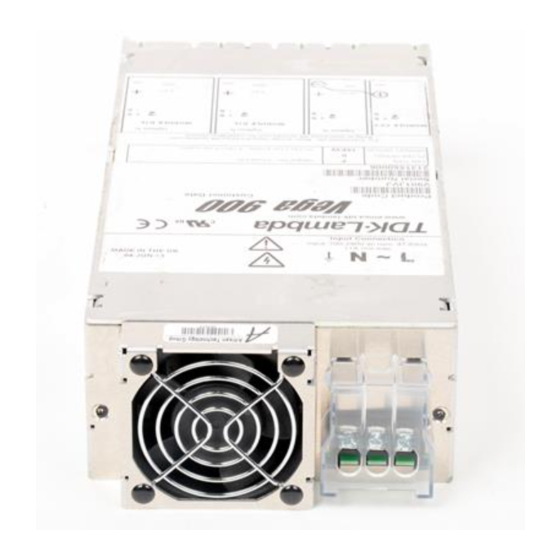
Vega 900 Handbook
Input Parameters
NOMINAL INPUT VOLTAGE RANGE
MAX. INPUT VOLTAGE RANGE
INPUT FREQUENCY
MAXIMUM INPUT CURRENT
INRUSH CURRENT
Output Parameters
Adjustment and Derating.
The Vega 900 series is designed to provide a max output power of 900W at nominal output volt-
ages. The following procedure must be used to ensure the PSU is operated within its ratings
a
Calculate user power for each module (volts x amps).
b
Add all the individual module powers together. The total power must not exceed the value
given.
c
Calculate secondary transformer turns x amps for each module. See the outputs table
for transformer secondary turns.
d
Add all the module turns x amps together and this must not exceed the ampere turns.
e
If necessary reduce the loading until the conditions are met, ie. power and ampere-turns
maxima.
Max
Dual Width
Max
Max AT
Option
Ambient
Modules Fitted
Power
(total)
F,D
No
900
(Standard or
Yes
900
Ruggedised
50
No
650
Fan Foward
Airflow
Q
No
750
(Quiet Fan
50
Yes
750
Foward
Aairflow
* Ruggedised fan (Papst 622HH, not for use in PSU's fitted with IEC inlet).
Note 1:The PSU main transformer has three regions for module secondaries seperated by two
primary windings. Starting nearest slot 1, region A, primary winding, region B, primary winding,
region C. The total ampere turns (AT) in any two adjacent regions is limited to that in the table
above column, " Max AT in adjacent regions (note 1)".See mains transformer regions table
below for modules allowed in each region. The table uses module widths with a twin output
module being single width
.
n/a=not applicable
Main transformer regions table:
Slot 1
Slot 1
Slot 5.5
Region A Region B
Region A
Region B
Region C
Single
Single
Dual
Dual
-
Blank
Dual
Dual
-
Single
Dual, Single
Single
-
Single
Dual
Single
-
Single
Dual
-
-
1.5
-
Dual
-
Single
Single
Single, Single, Single Single
1.5
Single
Single,Single
Single
Combined Modules
Single
Single
-
Single
-
Single
-
-
1.5
Dual
1.5
1.5
Single
Single
Dual
1.5
-
-
Dual
1.5
Single
Single
1.5,Single
Single
Single
Single
1.5
-
-
Single
1.5
Single
1.5
1.5
1.5,Single
Single
1.5
1.5
1.5
1.5
1.5
Customer Air Cooling (option C):
The following method must be used for determining the safe operation of PSUs when C option
165 - 240VAC
(Customer Air) is fitted, ie fan not fitted to PSU.
150 - 264VAC
For PSUs cooled by customer supplied airflow the components listed in the following table must
47- 63Hz
not exceed the temperatures given. Additionally ratings specified for units with an internal fan
9 A AC
must still be complied with, eg mains input voltage range, maximum output power, ampere turns,
<40 AMPS
module voltage / current ratings and maximum ambient temperature. To determine the component
temperatures the heating tests must be conducted in accordance with the requirements of
IEC/EN/CSA60950-1:2001 Clause 4.5. Consideration should also be give to the requirements of
other safety standards.
Test requirements include: PSU to be fitted in its end-use equipment and operated under the
most adverse conditions permitted in the end-use equipment handbook/specification and which
will result in the highest temperatures in the PSU. To determine the most adverse conditions
consideration should be given to the end use equipment maximum operating ambient, the PSU
loading and input voltage, ventilation, end use equipment orientation, the position of doors & cov-
ers, etc. Temperatures should be monitored using type K fine wire thermocouples (secured with
cyanoacrylate adhesive, or similar) placed on the hottest part of the component (out of any direct
airflow) and the equipment should be run until all temperatures have stabilised.
CIRCUIT REF.
-
T1, TX101, TX201
Max AT adjacent
Max Current
XQ1
regions (note 1)
Rating
XTR1
220
180
100%
TX1
220
180
100%
L1, L2, XT601
T2
220
n/a
100%
L4
Various
180
n/a
100%
RLY1
180
140
100%
C15
Various
C2, C3, C4
Various
Various
Modules
Modules
Note Output Range
B1L
B1H
B2
Slot 5.5
B3
Region C
B5
1.5
1.5
C1
1.5
1.5
C1Y
1
1.5
-
C3
Single,Single
Dual
1,5, Single
Single
C4
Dual, Single
Single
C5
1.5
-
D1L
2
Single, Single
Dual
D1H
2
1.5
Dual
D2
2
Dual
Dual
D3
2
Dual
Dual
D4
2
Dual
1.5
D5
2
Dual
1.5
E1
Dual
1.5
E2
3
1.5,1.5
Single
1.5,1.5
-
E3L
1.5,1.5
-
E3H
1.5, Dual
-
E4
1.5, Single
Single
E5L
1.5
1.5
E5H
DESCRIPTION
MAX. TEMP (°C)
Power transformer primary, secondary and core
Module current transformer windings
E & F Primary option transformers
EV & FV Primary option transformers
xEW & xFW Primary option transformers
Choke winding
Choke winding
Choke winding
All other choke & transformer windings
Relay
X capacitor
All other X capacitors
Electrolytic Capacitor
All other 10mm dia Electrolytic Capacitor
All other 12.5mm dia Electrolytic Capacitor
Max. Current
Current
Slots
Turns
Limit
Standard Modules
1.8-3.8V
20A
1
1
25A
3.9-5.5V
20A
1
1
25A
5.0-9V
25A
1
2
31.3A
9.1-16.2V
12A
1
3
15A
21.6-31V
6A
1
5
7.5A
1.8-4.1V
35A
1
1
43.8A
1.8-4.1V
40A
1
1
50A
9.1-16.2V
18A
1
3
22.5A
16.3-21.5V
14A
1
4
17.5A
21.6-31V
10A
1
5
12.5A
1.8-3.8V
50A
1.5
1
62.5A
3.9-5.5V
50A
1.5
1
62.5A
3.8-8V
45A
1.5
2
56.25A
8-16.5V
24A
1.5
3
30A
14-21.5V
18A
1.5
4
22.5A
21-28V
15A
1.5
5
18.75A
1.8-3.8V
60A
2
1
75A
3.8-8V
60A
2
2
75A
8-13.9V
40A
2
3
50A
14-15V
36A
2
3
45A
14-19.9V
30A
2
4
37.5A
20-24V
27A
5
33.8A
24-28V
25A
2
5
31.3A
Modules
Note
Output Range
L1
4.2-5.5V
1.8-3.8V
H1L/1L
1.8-3.8V
1.8V-3.8V
H1L/1H
3.9-5.5V
3.9-5.5V
H1H/1L
1.8-3.8V
3.9-5.5V
H1H/1H
3.9-5.5V
1.8-3.8V
H1L/2
5.6-9V
3.9-5.5V
H1H/2
5.6-9V
1.8-3.8V
130
H1L/3
9.1-16.2V
127
90
3.9-5.5V
H1H/3
90
9.1-16.2V
130
1.8-3.8V
110
H1L/4
117
16.3-25V
120
3.9-5.5V
110
H1H/4
16.3-25V
100
100
5.6-9V
H2/1L
105
1.8-3.8V
67
5.6-9V
80
H2/1H
3.9-5.5V
85
5.6-9V
H2/2
5.6-9V
Settings for hazard-
5.6-9V
H2/3
ous energy
9.1-16.2
5.6-9V
H2/4
-
16.3-25V
9.1-16.2V
H3/1L
>7.6V
1.8-3.8V
>16V
9.1-16.2V
>32V
H3/1H
3.9-5.5V
>5.4V
9.1-16.2V
-
H3/2
5.6-9V
>10.6V
9.1-16.2V
>13.7V
H3-3
9.1-16.2V
>19.2V
>3.8V
9.1-16.2V
H3/4
>3.8V
16.3-25V
>4.2V
16.2-28V
H5/1L
>8V
1.8-3.8V
>10.6V
16.2-28V
>12.8V
H5/1H
3.9-5.5V
>3.2V
16.2-28V
>3.2V
H5/2
5.6-9V
>4.8V
X1
6,7
0-10V
>5.3V
>6.4V
X2
6,7
0-20V
>7.1V
X4
6,7
0-40V
>7.6V
X8
6,7
0-80V
Part Number 17155
Max. Current
Settings for hazard-
Current
Slots
Turns
Limit
ous energy
Standard Modules
35A
1
1
43.8A
>5.4V
12A
1
15A
-
1
8A
1
12A
-
12A
1
15A
-
1
8A
1
12A
-
12A
1
15A
-
1
8A
1
12A
-
12A
1
15A
-
1
8A
1
12A
-
12A
1
15A
-
1
6A
2
9A
-
12A
1
15A
1
6A
2
9A
-
12A
1
15A
-
1
6A
3
9A
-
12A
1
15A
-
1
6A
3
7.5A
-
12A
1
15A
-
1
4.5A
4
6A
-
12A
1
15A
-
1
4.5A
4
6A
-
10A
2
15A
-
1
8A
1
12A
-
10A
2
15A
-
1
8A
1
12A
-
10A
2
15A
-
1
6A
2
9A
10A
2
15A
-
1
6A
3
7.5A
-
10A
2
15A
-
1
4.5A
4
6A
-
10A
3
15A
>16V
1
8A
1
12A
-
10A
3
15A
>16V
1
8A
1
12A
-
10A
3
15A
>16V
1
6A
2
9A
-
10A
3
15A
>16V
1
6A
3
7.5A
-
10A
3
15A
>16V
1
4.5A
4
6A
-
5A
5
7.5A
>32V
1
8A
1
12A
-
5A
5
7.5A
>32V
1
8A
1
12A
-
5A
5
7.5A
>32V
1
6A
2
9A
-
90A
1
-
-
64.5A
1
-
-
-
32.4A
1
-
---
16.2A
1
-
-
-
Advertisement
Table of Contents

Related Manuals for Lambda Vega 900


Summary of Contents for Lambda Vega 900
- Page 1 Test requirements include: PSU to be fitted in its end-use equipment and operated under the 1.8-3.8V The Vega 900 series is designed to provide a max output power of 900W at nominal output volt- most adverse conditions permitted in the end-use equipment handbook/specification and which 3.9-5.5V...
- Page 2 >19.2V 48.1-60V 12.5A danger, shock hazard These products are not customer serviceable. Repairs may only be carried out by Lambda UK or 28-36V 22.5A >10.6V their authorised agents. These products are not authorised for use as critical components in nuclear 42-56V 18.75A...
- Page 3 Vega 900 Handbook Part Number 17155 Special instructions for medical applications (IEC/EN/UL/CSA60601-1) Logic 0 = 0-0.8V. Logic 1 = 2.0 - 5.0V with respect to 0V (Pin 3) Module Good Applicable to products with L, R and T filter options only.
- Page 4 Vega 900 Handbook Part Number 17155 IEC 320 (Switched) Input Customer fixing s Customer Air and Fixing detail Customer fixings are M4 Customer fixings are M4 Quick Connect (Faston) Input Right Angle Screw Terminal Input Customer fixings are M4 Customer fixings are M4 CEL Part No.
Need help?
Do you have a question about the Vega 900 and is the answer not in the manual?
Questions and answers