
Related Manuals for Lambda LZS-A1500-3


Summary of Contents for Lambda LZS-A1500-3
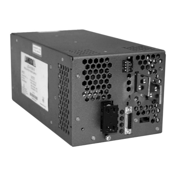
- Page 1 LZS-A1500-3 POWER SUPPLY Installation, Operation, and Maintenance Manual IM-L L ZSA1500-3 3 May 2008 Revision B...
-
Page 3: Table Of Contents
4) GUIDE TO APPLICATION Safety Notice Input Voltage Output Voltage Overvoltage Protection Circuit Adjustment Overtemperature and Overvoltage Shutdown Auxiliary Control and Alarm Signals 5) FIGURES Page. 1 3055 Del Sol Blvd • San Diego, CA 92154 • 1-800-LAMBDA-4 Revision B : May 2008... -
Page 4: Safety And Recommended Practices
LZS-A A 1500-3 3 Power Supply 1 Safety and Recommended Practices 1.1 General Safety Instructions This power supply is a switch mode power supply for use in applications meeting a Pollution Degree 2 environment. A suitable mechanical and fire enclosure must be provided by the end use equip- ment for shock hazard protection, fire protection and protection from hazardous energy levels. -
Page 5: Ratings And Specifications
100% rated load from -30°C to 60°C derate linearly to 60% @ 70°C (4%/°C) Start-up Temperature °C -40° to +70° Table 2 Page. 3 3055 Del Sol Blvd • San Diego, CA 92154 • 1-800-LAMBDA-4 Revision B : May 2008... - Page 6 No Safety agency approvals for 100-380 VDC opercation Minimum Turn-ON voltage for DC Input is 110VDC, unit will operate as low as 65 VDC after power-up. Lambda does not recommend operation below 100VDC for more than one minute, or damage may occur.
-
Page 7: Features
500 volts, minimum. 3000 VAC isolation from AC input to all auxiliary signals. Synchronization (Sync) Auxiliary signal at approximately 200khz (switching frequency of unit) used for synchronizing with other equipment. Table 8 Page. 5 3055 Del Sol Blvd • San Diego, CA 92154 • 1-800-LAMBDA-4 Revision B : May 2008... - Page 8 LZS-A A 1500-3 3 Power Supply Protection Features Output Voltage Range 18-29.4V Nominal Factory Set Point Overvoltage Protection (adjustable) 20-34V (Factory set to 31.0V) Overcurrent Protection Factory set to 110% min. and 130% max. Thermal Protection Self-resetting thermostat.* Fusing Internal Isolation Voltages 4242 VDC, Input to Output 2121 VDC, Input to Chassis Ground...
-
Page 9: Guide To Application
LZSa power supplies provide auxiliary control and alarm signals per page 5. These signals are accessible via the15-pin, sub miniature "D" connector, located below the output terminals of the unit. Page. 7 3055 Del Sol Blvd • San Diego, CA 92154 • 1-800-LAMBDA-4 Revision B : May 2008... -
Page 10: Figures
LZS-A A 1500-3 3 Power Supply 5. Figures Figure 1 - PIN Assignments for TB201 and chassis mounted “D” connector Page. 8 Revision B : May 2008... - Page 11 Figure 2 - Typical Local Sense Connection LS = Local Sense S = Remote Sense Figure 3 - Typical Remote Sense Connection Page. 9 3055 Del Sol Blvd • San Diego, CA 92154 • 1-800-LAMBDA-4 Revision B : May 2008...
- Page 12 LZS-A A 1500-3 3 Power Supply LS = Local Sense S = Remote Sense Figure 4 - Remote Voltage Control with an External Programming Resistor or Voltage Source (Local Sensing) LS = Local Sense S = Remote Sense Figure 5 - Remote Voltage Control with an External Programming Resistor or Voltage Source (Remote Sensing) Page.
- Page 13 LZS-A A 1500-3 3 Power Supply Figure 6 - Parallel Operation Page. 11 3055 Del Sol Blvd • San Diego, CA 92154 • 1-800-LAMBDA-4 Revision B : May 2008...
- Page 14 LZS-A A 1500-3 3 Power Supply Figure 7 - Series Operation Page. 12 Revision B : May 2008...
- Page 15 LZS-A A 1500-3 3 Power Supply Figure 8 - Outline Drawing Page. 13 3055 Del Sol Blvd • San Diego, CA 92154 • 1-800-LAMBDA-4 Revision B : May 2008...
Need help?
Do you have a question about the LZS-A1500-3 and is the answer not in the manual?
Questions and answers