Mitsubishi Electric FX2N-32CCL Installation Manual
Melsec-f/fx2n series
Hide thumbs
Also See for FX2N-32CCL:
- Hardware manual (154 pages) ,
- Hardware manual (140 pages) ,
- Training manual (284 pages)
Advertisement
Quick Links
JY997D52401C
Side
JAPANESE
A
Side
ENGLISH
B
FX
-32CCL
2N
INSTALLATION MANUAL
Manual Number
JY997D52401
Revision
C
Date
September 2017
This manual describes the part names, dimensions, mounting, and specifications
of the product. Before use, read this manual and the manuals of all relevant
products fully to acquire proficiency in handling and operating the product. Make
sure to learn all the product information, safety information, and precautions.
Store this manual in a safe place so that it can be taken out and read whenever
necessary. Always forward it to the end user.
Registration:
The company and product names described in this manual are registered
trademarks or the trademarks of their respective companies.
Effective September 2017
Specifications are subject to change without notice.
2013 Mitsubishi Electric Corporation
Safety Precaution
(Read these precautions before use.)
This manual classifies the safety precautions into two categories:
and
.
Indicates that incorrect handling may cause hazardous
conditions, resulting in death or severe injury.
Indicates that incorrect handling may cause hazardous
conditions, resulting in medium or slight personal injury
or physical damage.
Depending on the circumstances, procedures indicated by
also cause severe injury.
It is important to follow all precautions for personal safety.
Associated Manuals
Manual name
Manual No.
Description
JY992D71801
FX
2N
-32CCL
Describes details of the FX
MODEL CODE:
User's Manual
32CCL CC-Link Interface block.
09R711
FX
Series
JY997D31301
Explains the FX
Series PLC
3G
3G
User's Manual
MODEL CODE:
specifications for I/O, wiring,
- Hardware Edition
09R521
installation, and maintenance.
FX
3GC
Series
JY997D45401
Explains the FX
3GC
Series PLC
User's Manual
MODEL CODE:
specifications for I/O, wiring,
- Hardware Edition
09R533
installation, and maintenance.
FX
Series
JY997D16501
Explains the FX
Series PLC
3U
3U
User's Manual
MODEL CODE:
specifications for I/O, wiring,
- Hardware Edition
09R516
installation, and maintenance.
FX
Series
JY997D28701
Explains the FX
Series PLC
3UC
3UC
User's Manual
MODEL CODE:
specifications for I/O, wiring,
- Hardware Edition
09R519
installation, and maintenance.
FX
Series
JY992D66301
E x p l a i n s F X
S e r i e s P L C
2N
2 N
H A R D WA R E
MODEL CODE:
specification details for I/O, wiring,
MANUAL
09R508
installation, and maintenance.
Explains FX
2NC
(D/UL) Series
FX
(D/UL) Series
2NC
PLC specification details for I/O,
H A R D WA R E
JY992D87201
w i r i n g ,
i n s t a l l a t i o n ,
MANUAL
maintenance.
FX
(DSS/DS)
Explains FX
(DSS/DS) Series
2NC
2NC
JY992D76401
Series
PLC specification details for I/O,
MODEL CODE:
H A R D WA R E
w i r i n g ,
i n s t a l l a t i o n ,
09R509
MANUAL
maintenance.
Side
B
Manual name
Manual No.
JY992D89301
E x p l a i n s F X
FX
1N
Series
MODEL CODE:
specification details for I/O, wiring,
HARDWARE MANUAL
09R511
installation, and maintenance.
Explains FX
FX
/FX
Series
0
0N
JY992D47501
specification details for I/O, wiring,
HARDWARE MANUAL
installation, and maintenance.
FX
/FX
/FX
/FX
/
3S
3G
3GC
3U
Explains basic instructions and
FX
Series
JY997D16601
3UC
applied instructions available in the
Programming Manual
MODEL CODE:
FX
/FX
3S
- Basic & Applied Instruction
09R517
PLC.
Edition
FX
, FX
, FX
, FX
JY992D88101
1S
1N
2N
2NC
Explains instructions applicable in
Series
MODEL CODE:
the FX
1S
Programming Manual
09R512
How to obtain manuals
For product manuals or documents, consult with the Mitsubishi Electric dealer from
who you purchased your product.
Compliance with EC directive (CE Marking)
This note does not guarantee that an entire mechanical module produced in
accordance with the contents of this note will comply with the following standards.
Compliance to EMC directive and LVD directive for the entire mechanical module
should be checked by the user / manufacturer. For more information please consult
with your nearest Mitsubishi product provider.
Regarding the standards that comply with the main unit, please refer to either the FX
series product catalog or consult with your nearest Mitsubishi product provider.
Requirement for Compliance with EMC directive
The following products have shown compliance through direct testing (of the identified
standards below) and design analysis (through the creation of a technical construction
file) to the European Directive for Electromagnetic Compatibility (2014/30/EU) when
used as directed by the appropriate documentation.
Attention
This product is designed for use in industrial applications.
Type:
Programmable Controller (Open Type Equipment)
Models:
MELSEC FX
series manufactured
2N
from June 1st, 1999
FX
-32CCL
2N
Standard
Remark
EN61000-6-4:2007
C omp lia nce w ith a ll rele van t aspe cts of th e
Generic emission standard
standard.
Industrial environment
• Emission-Enclosure port
may
• Emission-Low voltage AC mains port
• Emission-Telecommunications/network port
EN61131-2:2007
C omp lia nce w ith a ll rele van t aspe cts of th e
Programmable controllers
standard.
- Equipment requirements
EMI
and tests
• Radiated Emission
• Conducted Emission
2N
-
EMS
• Radiated electromagnetic field
• Fast transient burst
• Electrostatic discharge
• High-energy surge
• Voltage drops and interruptions
• Conducted RF
• Power frequency magnetic field
1. Introduction
1.1 Introduction
The CC-Link interface block FX
-32CCL is a special function block to connect the
2N
FX
/FX
/FX
/FX
/FX
/FX
/FX
/FX
Series PLC to a CC-Link network.
0N
1N
2N
2NC
3G
3GC
3U
3UC
For details, refer to the FX
1.2 Incorporated Items
Check to ensure the following product and items are included in the package.
Included Item
FX
-32CCL
2N
a n d
Special unit/block No. label
Dust proof protection sheet
Manuals (Japanese version, English version)
a n d
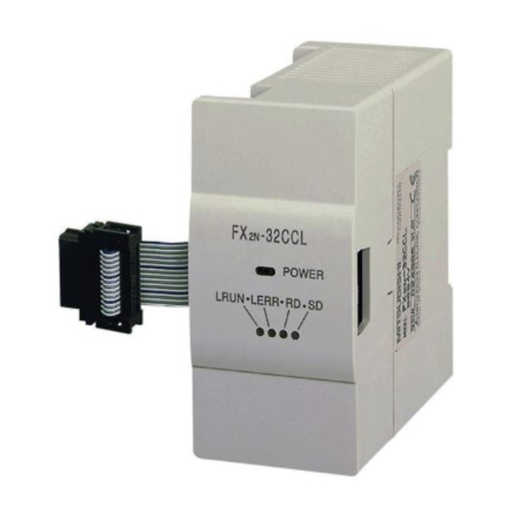
1.3 External Dimensions and Part Names
Description
[2]
2-4.5 mounting holes
S e r i e s P L C
1 N
[1]
0
/FX
0N
Series PLC
[3]
/FX
/FX
/FX
3G
3GC
3U
3UC
[4]
4 (0.16")
43 (1.69")
/FX
1N
/FX
2N
/FX
2NC
PLC.
[Without top cover]
[8]
[9]
[10]
[11]
[12]
[13]
[1]
Extension cable
[2]
Direct mounting hole
2 holes of 4.5 (0.18") (mounting screw: M4 screw)
[3]
Power LED (green)
[4]
Status LEDs
[5]
Name plate
[6]
DIN rail mounting groove (DIN rail: DIN46277, 35 mm (1.38") width)
[7]
DIN rail mounting hook
[8]
Power supply terminal block
[9]
Station No. set switch
[10]
Number of occupied stations set switch
[11]
Baud rate set switch
[12]
Next step extension connector
[13]
CC-Link connection terminal block
1.4 Power and status LEDs
LED display
LED color
Indicates power status of FX
POWER
green
Lighted when 5 V is supplied from PLC.
L RUN
Red
Lit while communication is performed correctly.
Lit when a communication error has occurred.
Lit when a rotary switch is incorrectly set.
L ERR
Red
Flickers when setting of a rotary switch is changed while
the power is turned on.
RD
Red
Lit while data is received.
SD
Red
Lit while data is sent.
1.5 Terminal Layout
Power supply
terminal block
2N
-32CCL User's Manual.
1 unit
CC-Link connection
terminal block
1 sheet
1 sheet
1 manual each
1.5.1
Terminal screws and tightening torque
[5]
For the terminals of FX
Tighten the screws to a torque of 0.5 to 0.8 N m.
Do not tighten terminal screws with a torque outside the above-mentioned range.
Failure to do so may cause equipment failures or malfunctions.
For details on the wiring needed to connect to the terminal blocks shown in the
figure above, refer to the following manual.
[6]
1.6 Switch setting
The station number, the number of occupied stations and the baud rate can be set
using rotary switches provided inside the panel cover of the FX
switch settings become valid after FX
[7]
If the switch settings are changed after FX
flicker. To change the switch setting, power OFF the FX
power it ON again.
For details on the switch setting, refer to the following manual.
87 (3.42")
1.6.1
Station number setting
One to four FX
2N
station number set here is not assigned to an other unit.
Unit: mm (inches)
Setting items
MASS (Weight): Approx. 0.2 kg (0.44 lbs)
10
1
1.6.2
Baud rate (Transmission speed) setting
Set the transmission speed in accordance with the specifications of the maximum
transmission distance and the transmission speed.
For specifications of the maximum transmission distance and
Setting
0
1
2
3
4
5 to 9
1.6.3
Number of occupied station setting
The number of remote device points is determined by the number of stations set
here.
Setting
Description
0
-32CCL.
2N
1
2
3
4 to 9
2. Installation
INSTALLATION
PRECAUTIONS
Make sure to cut off all phases of the power supply externally before
attempting installation work.
Failure to do so may cause electric shock or damage to the product.
INSTALLATION
PRECAUTIONS
Use the product within the generic environment specifications described in
section 3.2 of this manual.
Never use the product in areas with excessive dust, oily smoke, conductive
dusts, corrosive gas (salt air, Cl
vibration or impacts, or expose it to high temperature, condensation, or rain
and wind.
If the product is used in such conditions, electric shock, fire, malfunctions,
deterioration or damage may occur.
Do not touch the conductive parts of the product directly.
Doing so may cause device failures or malfunctions.
Install the product securely using a DIN rail or mounting screws.
-32CCL, M3 screws are used.
2N
Refer to the FX
-32CCL User's Manual.
2N
-32CCL. The
2N
-32CCL startup.
2N
-32CCL startup, the L ERR LED will
2N
-32CCL once, and
2N
Refer to the FX
-32CCL User's Manual.
2N
-32CCL units can be used at a time. Pay attention so that the
Range
Description
0 to 6
1 to 64
0, 65 to 99 is the setting error.
0 to 9
transmission speed, refer to Section 3.5.
Description
Transmission speed 156 Kbps
Transmission speed 625 Kbps
Transmission speed 2.5 Mbps
Transmission speed 5 Mbps
Transmission speed 10 Mbps
Setting error
For specifications of number of occupied station and
number of remote points, refer to Section 3.6.
Description
1 station
2 stations
3 stations
4 stations
Unusable
, H
S, SO
, or NO
), flammable gas,
2
2
2
2
Advertisement

Related Manuals for Mitsubishi Electric FX2N-32CCL


Summary of Contents for Mitsubishi Electric FX2N-32CCL
- Page 1 One to four FX -32CCL units can be used at a time. Pay attention so that the For product manuals or documents, consult with the Mitsubishi Electric dealer from station number set here is not assigned to an other unit.
- Page 2 This manual confers no industrial property rights or any rights of any other kind, failure. Remote output RY50 to RY5F Remote input RX50 to RX5F nor does it confer any patent licenses. Mitsubishi Electric Corporation cannot be Otherwise, malfunctions may cause serious accidents. Number of I/O occupied (set station+2)
- Page 3 One to four FX -32CCL units can be used at a time. Pay attention so that the For product manuals or documents, consult with the Mitsubishi Electric dealer from station number set here is not assigned to an other unit.
Need help?
Do you have a question about the FX2N-32CCL and is the answer not in the manual?
Questions and answers