
Related Manuals for Microchip Technology MCP39F521


Summary of Contents for Microchip Technology MCP39F521
- Page 1 MCP39F521 Power Monitor Demonstration Board User’s Guide 2015 Microchip Technology Inc. DS50002413A...
- Page 2 ViewSpan, WiperLock, Wireless DNA, and ZENA are trademarks of Microchip Technology Incorporated in the U.S.A. and other countries. SQTP is a service mark of Microchip Technology Incorporated in the U.S.A. Silicon Storage Technology is a registered trademark of Microchip Technology Inc. in other countries.
- Page 3 Object of Declaration: MCP39F521 Power Monitor Demonstration Board 2015 Microchip Technology Inc. DS50002413A-page 3...
- Page 4 MCP39F521 Power Monitor Demonstration Board User’s Guide NOTES: 2015 Microchip Technology Inc. DS50002413A-page 4...
-
Page 5: Table Of Contents
Customer Support ....................9 Document Revision History ................... 9 Chapter 1. Product Overview 1.1 Introduction ....................11 1.2 What the MCP39F521 Power Monitor Demonstration Board Kit Includes ... 12 Chapter 2. Installation and Operation 2.1 Getting Started ..................... 13 Chapter 3. Hardware Description 3.1 Input and Analog Front End ................. - Page 6 MCP39F521 Power Monitor Demonstration Board User’s Guide NOTES: 2015 Microchip Technology Inc. DS50002413A-page 6...
-
Page 7: Preface
• Document Revision History DOCUMENT LAYOUT This document describes how to use the MCP39F521 Power Monitor Demonstration Board to evaluate the MCP39F521 device. The manual layout is as follows: • – Provides important information about the Chapter 1. “Product Overview”... -
Page 8: Conventions Used In This Guide
MCP39F521 Power Monitor Demonstration Board User’s Guide CONVENTIONS USED IN THIS GUIDE This manual uses the following documentation conventions: DOCUMENTATION CONVENTIONS Description Represents Examples Arial font: ® Italic characters Referenced books MPLAB IDE User’s Guide Emphasized text ...is the only compiler... -
Page 9: Recommended Reading
Preface RECOMMENDED READING This user's guide describes how to use the MCP39F521 Power Monitor Demonstration Board. Other useful documents are listed below. The following Microchip documents are available and recommended as supplemental reference resources. MCP39F521 Data Sheet – “I Single Phase Energy and Power Monitoring IC with Calculation”... - Page 10 MCP39F521 Power Monitor Demonstration Board User’s Guide NOTES: 2015 Microchip Technology Inc. DS50002413A-page 10...
-
Page 11: Chapter 1. Product Overview
RMS voltage, active energy (both import and export), reactive energy and other typical power quantities as defined in the MCP39F521 data sheet. The “MCP39F521 Power Monitor Utility” software is used to calibrate and monitor the system, and can be used to create custom calibration setups. For most accuracy requirements, only a single-point calibration is needed. -
Page 12: What The Mcp39F521 Power Monitor Demonstration Board Kit Includes
MCP39F521 Power Monitor Demonstration Board User’s Guide WHAT THE MCP39F521 POWER MONITOR DEMONSTRATION BOARD KIT INCLUDES This MCP39F521 Power Monitor Demonstration Board kit includes: • MCP39F521 Power Monitor Demonstration Board (ADM00686) • AC Line Cable • IEC-to-Female AC Load Cable •... -
Page 13: Chapter 2. Installation And Operation
DEMONSTRATION BOARD USER’S GUIDE Chapter 2. Installation and Operation GETTING STARTED To use the MCP39F521 Power Monitor Demonstration Board, follow the steps described in the following sections. The meter design uses a 5A load for calibration current and a maximum current (I ) of 15A. - Page 14 MCP39F521 Power Monitor Demonstration Board User’s Guide NOTES: 2015 Microchip Technology Inc. DS50002413A-page 14...
-
Page 15: Chapter 3. Hardware Description
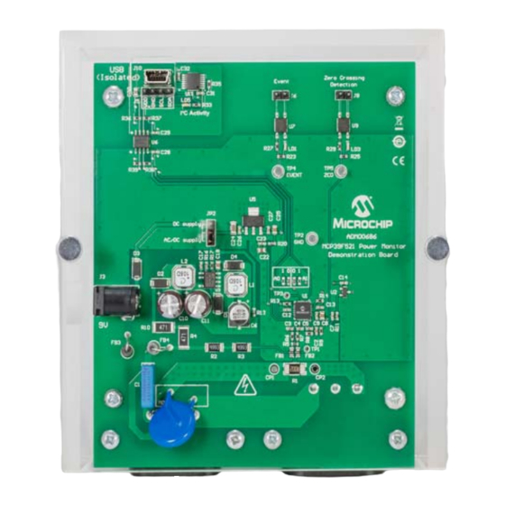
MCP39F521 POWER MONITOR DEMONSTRATION BOARD USER’S GUIDE Chapter 3. Hardware Description This chapter identifies the main features of the MCP39F521 board and describes the circuits. Figure 3-1 illustrates the components on the top view. Legend: USB Connection (isolated) Switching AC/DC Power Supply... - Page 16 MCP39F521 Power Monitor Demonstration Board User’s Guide Figure 3-2 illustrates the components on the board’s bottom view. Legend: Load connection (15A maximum recommended current) Line connection AC supply (90-230V) FIGURE 3-2: MCP39F521 Power Monitor Demonstration Board Bottom View. 2015 Microchip Technology Inc.
-
Page 17: Input And Analog Front End
Hardware Description INPUT AND ANALOG FRONT END The MCP39F521 Power Monitor Demonstration Board will operate from 90V to 230V. At the bottom of the main board are the high-voltage line and neutral connections. The shunt sits on the neutral side, or low side, of a two-wire system. The board comes populated with a surface mount 2 mΩ... -
Page 18: Power Supply Circuit
MCP39F521 Power Monitor Demonstration Board User’s Guide POWER SUPPLY CIRCUIT The power supply circuit for the MCP39F521 Power Monitor Demonstration Board is shown in Figure 3-4. 8LNK304 8.2 K 4.7 µF 150 FB 470 470 2.05 K 0.1 µF 4.7 µF 4.7 µF... -
Page 19: Appendix A. Schematic And Layouts
MCP39F521 POWER MONITOR DEMONSTRATION BOARD USER’S GUIDE Appendix A. Schematic and Layouts INTRODUCTION This appendix contains the following schematics and layouts for of the MCP39F521 Power Monitor Demonstration Board: • Board – MCP39F521 Schematic • Board – Power and USB Schematic •... -
Page 20: Board - Mcp39F521 Schematic
BOARD – MCP39F521 SCHEMATIC EVENT EVENT 0603 0603 3.3A 3.3D 3.3A 3.3A Event 0.1 μF 0.1 μF HCPL-181 HDR-2.54 Male 1x2 0603 0603 4.7k TP PAD PCB 1.2x0.7 Current channel 0603 RESET COMMON_A AGND DGND DGND DGND NEUTRAL COMMON_B AVDD... -
Page 21: Board - Power And Usb Schematic
BOARD – POWER AND USB SCHEMATIC 5VUSB 0.1 μF 5VUSB Isolation 3.3D 0603 5VUSB Barrier USB MINI-B Female GND_ISO 5VUSB 5VUSB 5VUSB 3.3D 3.3D VBUS GND_ISO USB_N 0.1 μF 0.1 μF 4.7 μF 5VUSB USB_P 0603 0603 2.1k 2.1k 2.1k 2.1k GND_ISO 0805... -
Page 22: Board - Top Silk
MCP39F521 Power Monitor Demonstration Board User’s Guide BOARD – TOP SILK 2015 Microchip Technology Inc. DS50002413A-page 22... -
Page 23: Board - Top Copper And Silk
Schematic and Layouts BOARD – TOP COPPER AND SILK 2015 Microchip Technology Inc. DS50002413A-page 23... -
Page 24: Board - Top Copper
MCP39F521 Power Monitor Demonstration Board User’s Guide BOARD – TOP COPPER 2015 Microchip Technology Inc. DS50002413A-page 24... -
Page 25: Board - Bottom Copper
Schematic and Layouts BOARD – BOTTOM COPPER 2015 Microchip Technology Inc. DS50002413A-page 25... -
Page 26: Board - Bottom Copper And Silk
MCP39F521 Power Monitor Demonstration Board User’s Guide BOARD – BOTTOM COPPER AND SILK 2015 Microchip Technology Inc. DS50002413A-page 26... -
Page 27: A.10 Board - Bottom Silk
Schematic and Layouts A.10 BOARD – BOTTOM SILK 2015 Microchip Technology Inc. DS50002413A-page 27... - Page 28 MCP39F521 Power Monitor Demonstration Board User’s Guide NOTES: 2015 Microchip Technology Inc. DS50002413A-page 28...
-
Page 29: Appendix B. Bill Of Materials (Bom)
Conn. Header-2.54 Male 1x3 Gold 68000-103HLF 5.84 MH TH Vert. The components listed in this Bill of Materials are representative of the PCB assembly. The released BOM Note 1: used in manufacturing uses all RoHS-compliant components. 2015 Microchip Technology Inc. DS50002413A-page 29... - Page 30 MCP39F521 Power Monitor Demonstration Board User’s Guide TABLE B-1: BILL OF MATERIALS (BOM) (CONTINUED) Qty. Designator Description Manufacturer Part Number Mech. HW Jumper 2.54 mm 1x2 Handle TE Connectivity, Ltd. 881545-2 Gold L1, L2 Inductor 1 mH 240 mA 20% SMD...
- Page 31 B&F Fasteners Supply PMS 632 0038 PH The components listed in this Bill of Materials are representative of the PCB assembly. The released BOM Note 1: used in manufacturing uses all RoHS-compliant components. 2015 Microchip Technology Inc. DS50002413A-page 31...
-
Page 32: Worldwide Sales And Service
Tel: 886-2-2508-8600 Tel: 631-435-6000 China - Xian Tel: 86-29-8833-7252 Fax: 886-2-2508-0102 San Jose, CA Fax: 86-29-8833-7256 Tel: 408-735-9110 Thailand - Bangkok Tel: 66-2-694-1351 Canada - Toronto Fax: 66-2-694-1350 Tel: 905-673-0699 Fax: 905-673-6509 07/14/15 2015 Microchip Technology Inc. DS50002413A-page 32... - Page 33 Mouser Electronics Authorized Distributor Click to View Pricing, Inventory, Delivery & Lifecycle Information: Microchip ADM00686...
Need help?
Do you have a question about the MCP39F521 and is the answer not in the manual?
Questions and answers