
Related Manuals for Microchip Technology MCP3421 SOT23-6


Summary of Contents for Microchip Technology MCP3421 SOT23-6
- Page 1 MCP3421 SOT23-6 Evaluation Board User’s Guide © 2009 Microchip Technology Inc. DS51793A...
- Page 2 PowerMate, PowerTool, REAL ICE, rfLAB, Select Mode, Total Endurance, WiperLock and ZENA are trademarks of Microchip Technology Incorporated in the U.S.A. and other countries. SQTP is a service mark of Microchip Technology Incorporated in the U.S.A. All other trademarks mentioned herein are property of their respective companies.
-
Page 3: Table Of Contents
Document Revision History ................... 4 Chapter 1. Quick Start Instructions 1.1 Introduction ..................... 5 1.2 Description of the MCP3421 SOT23-6 Evaluation Board ......5 1.3 Getting Started with PICkit Serial Analyzer ............ 7 Appendix A. Schematic and Layouts A.1 Introduction ....................23 A.2 Board –... - Page 4 MCP3421 SOT23-6 Evaluation Board User’s Guide NOTES: © 2009 Microchip Technology Inc. DS51793A-page iv...
-
Page 5: Preface
• Customer Support • Document Revision History DOCUMENT LAYOUT This document describes how to use the MCP3421 SOT23-6 Evaluation Board as a development tool to emulate and debug firmware on a target board. The manual layout is as follows: • Chapter 1. “Quick Start Instructions” – this chapter provides an overview of the MCP3421 SOT23-6 Evaluation Board and instructions on how to obtain the ADC conversion results using the PICKit Serial Analyzer. -
Page 6: Conventions Used In This Guide
MCP3421 SOT23-6 Evaluation Board User’s Guide CONVENTIONS USED IN THIS GUIDE This manual uses the following documentation conventions: DOCUMENTATION CONVENTIONS Description Represents Examples Arial font: ® Italic characters Referenced books MPLAB IDE User’s Guide Emphasized text ...is the only compiler... -
Page 7: Recommended Reading
Preface RECOMMENDED READING This user's guide describes how to use the MCP3421 SOT23-6 Evaluation Board with the PICkit Serial Analyzer. The following Microchip documents are available and rec- ommended as supplemental reference resources. PICkit™ Serial Analyzer User’s Guide, DS51647 Consult this document for instructions on how to use the PICkit Serial Analyzer hardware and software. -
Page 8: Document Revision History
MCP3421 SOT23-6 Evaluation Board User’s Guide DOCUMENT REVISION HISTORY Revision A (January 2009) • Initial Release of this Document. © 2009 Microchip Technology Inc. DS51793A-page 4... -
Page 9: Chapter 1. Quick Start Instructions
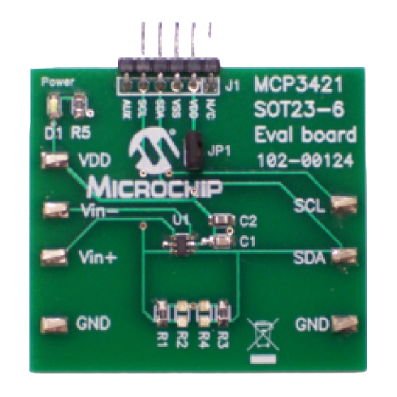
MCP3421 SOT23-6 Evaluation Board, and provides the I C communication PC to the MCP3421 SOT23-6 Evaluation Board. The user also can use this MCP3421 SOT23-6 Evaluation Board without the PICkit Serial Analyzer by providing the I communication signal to the SDA and SCL test pads on the board. - Page 10 MCP3421 SOT23-6 Evaluation Board User’s Guide FIGURE 1-1: Front and Back Views of the MCP3421 SOT23-6 Evaluation Board. © 2009 Microchip Technology Inc. DS51793A-page 6...
-
Page 11: Getting Started With Pickit Serial Analyzer
Quick Start Instructions GETTING STARTED WITH PICKIT SERIAL ANALYZER Figure 1-1 shows the MCP3421 SOT23-6 Evaluation Board and Figure 1-2 shows the Evaluation Board and PICkit Serial Analyzer connection. The following steps describe how to use them together: 1. Connect the MCP3421 SOT23-6 Evaluation Board’s J1 pin socket to the PICkit Serial Analyzer as shown in Figure 1-2. - Page 12 Personal Computer USB Cable Connected between the PICkit Serial Analyzer and Personal Computer PICkit Serial Analyzer Sensor Input Connectors MCP3421 Evaluation Board FIGURE 1-2: MCP3421 SOT23-6 Evaluation Board with the PICkit Serial Analyzer. © 2009 Microchip Technology Inc. DS51793A-page 8...
- Page 13 Click the Next button and follow the instructions. FIGURE 1-3: PICkit Serial Analyzer Configuration Wizard Welcome Window. 4. Select the I C Master option as communication mode, and click the Next button. FIGURE 1-4: Step 1 - Communication Mode Selection. © 2009 Microchip Technology Inc. DS51793A-page 9...
- Page 14 400 kHz only. 6. Select No on Enable Pull-ups, and click the Next button. Note: The MCP3421 SOT23-6 Evaluation Board has its own pull-up resistors, therefore, you don’t need additional pull-up resistors from the PICkit Serial Analyzer. FIGURE 1-6: Step 3 - Device Pullups Window.
- Page 15 If you choose PICkit Serial will power my device and 5 Volt as shown below, the MCP3421 SOT23-6 Evaluation Board is powered by the 5V DC from the PICkit™ Serial Analyzer through the JP1 jumper. In this case, make sure that the JP1 jumper on the MCP3421 SOT23-6 Evaluation Board is connected.
- Page 16 MCP3421 SOT23-6 Evaluation Board User’s Guide 8. Click the OK button. You have made all of the PICkit Serial Analyzer configura- tion set-ups. You are now ready to program the MCP3421 SOT23-6 Evaluation Board using the PICkit Serial Analyzer. FIGURE 1-8: Configuration Wizard - Finishing Step.
- Page 17 Creating Script Files In order to make a communication between the PICkit Serial Analyzer and the MCP3421 SOT23-6 Evaluation Board, a script file is needed. The following procedure shows how to create script files and how to use them. • Select Communication -----> Script ---> Script Builder FIGURE 1-9: Creating a Script File with Script Builder.
- Page 18 MCP3421 SOT23-6 Evaluation Board User’s Guide 1.3.2.1 CREATING A SCRIPT FILE FOR CONFIGURATION BYTE WRITING Click on WriteBlockAddrA8 in “Example I C Scripts” column. • This will result in filling in the spaces under the Script Detail column. Now you can modify the Script Detail column parameters by clicking with the right mouse button.
- Page 19 All 6 parameters above must be listed in the same order as shown here. The parameter above with * are not modifiable. Address bits (A2, A1, A0) = (0,0,0) for this evaluation board. See the MCP3421 Data Sheet for more information on address bit selection. © 2009 Microchip Technology Inc. DS51793A-page 15...
- Page 20 MCP3421 SOT23-6 Evaluation Board User’s Guide 2 Bytes to send Address Byte Configuration Byte (9C) Note that the “9C” in the configuration byte selects the following options: - Conversion Mode: Continuous Conversion - Bit Resolution: 18 bits - Gain Selection: 1x...
- Page 21 “Script Detail” column. Try again until the “Busy” LED goes OFF immediately after executing the write command. Zoom-in Zoom-in Write Command with Address bits Configuration Bits FIGURE 1-12: C Write Command Waveforms for the MCP3421. © 2009 Microchip Technology Inc. DS51793A-page 17...
- Page 22 MCP3421 SOT23-6 Evaluation Board User’s Guide 1.3.3 Reading the Conversion Data using the PICkit™ Serial Analyzer You can read back the conversion data by following the next steps. 1.3.3.1 CREATING A SCRIPT FILE TO READ THE CONVERSION DATA Click on ReadAddrA8 in “Example I2C Scripts” column.
- Page 23 Serial Analyzer from your computer and re-check the parameter values including the order of parameters under the “Script Detail” column. Try again until the “Busy” LED goes OFF immediately after executing the read command. © 2009 Microchip Technology Inc. DS51793A-page 19...
- Page 24 MCP3421 SOT23-6 Evaluation Board User’s Guide Requesting 5 Bytes Reading Conversion Data 5th Byte: Repeated Byte for Configuration byte (note that RDY bit returned to “1” after 4th byte) 4th byte: Configuration Byte (note that RDYbit is “0”) 3rd byte: Data Byte...
- Page 25 After the RDY bit is read out at the 4th byte, the RDY bit becomes “1” in the 5th byte (repeated byte). This means the device is now in the process of a new conversion and the latest conversion result is not ready yet. © 2009 Microchip Technology Inc. DS51793A-page 21...
- Page 26 MCP3421 SOT23-6 Evaluation Board User’s Guide NOTES: © 2009 Microchip Technology Inc. DS51793A-page 22...
-
Page 27: Appendix A. Schematic And Layouts
This appendix contains the following schematics and layouts for the MCP3421 SOT23-6 Evaluation Board: • Board – Schematic • Board – Top Layer • Board – Top Metal Layer • Board – Bottom Layer © 2009 Microchip Technology Inc. DS51793A-page 23... -
Page 28: Board - Schematic
MCP3421 SOT23-6 Evaluation Board User’s Guide BOARD – SCHEMATIC © 2009 Microchip Technology Inc. DS51793A-page 24... -
Page 29: Board - Top Layer
Schematic and Layouts BOARD – TOP LAYER © 2009 Microchip Technology Inc. DS51793A-page 25... -
Page 30: Board - Top Metal Layer
MCP3421 SOT23-6 Evaluation Board User’s Guide BOARD – TOP METAL LAYER © 2009 Microchip Technology Inc. DS51793A-page 26... -
Page 31: Board - Bottom Metal Layer
Schematic and Layouts BOARD – BOTTOM METAL LAYER © 2009 Microchip Technology Inc. DS51793A-page 27... - Page 32 MCP3421 SOT23-6 Evaluation Board User’s Guide NOTES: © 2009 Microchip Technology Inc. DS51793A-page 28...
-
Page 33: Appendix B. Bill Of Materials (Bom)
TEST POINT PC COMPACT SMT Keystone Electronics 5016 GND SCL SDA Note: The components listed in this Bill of Materials are representative of the PCB assembly. The released BOM used in manufacturing uses all RoHS-compliant components. © 2009 Microchip Technology Inc. DS51793A-page 29... -
Page 34: Worldwide Sales And Service
Fax: 86-592-2388130 Fax: 886-2-2508-0102 Toronto China - Xian Thailand - Bangkok Mississauga, Ontario, Tel: 86-29-8833-7252 Tel: 66-2-694-1351 Canada Fax: 86-29-8833-7256 Fax: 66-2-694-1350 Tel: 905-673-0699 China - Zhuhai Fax: 905-673-6509 Tel: 86-756-3210040 Fax: 86-756-3210049 01/16/09 © 2009 Microchip Technology Inc. DS51793A-page 30... - Page 35 Mouser Electronics Authorized Distributor Click to View Pricing, Inventory, Delivery & Lifecycle Information: Microchip MCP3421EV...
Need help?
Do you have a question about the MCP3421 SOT23-6 and is the answer not in the manual?
Questions and answers