Table of Contents
Advertisement
25080 - Puegnago del Garda (BS) ITALY
T. +39 0365 555909
F. +39 0365 651822
IT
MANUALE DI ISTRUZIONI
INSTALLAZIONE-USO-MANUTENZIONE
EN
INSTALLATION, USE AND
MAINTENANCE INSTRUCTION MANUAL
FR
MANUEL D'INSTRUCTIONS D'INSTALLATION-
D'UTILISATION-ET D'ENTRETIEN
ES
MANUAL DE INSTRUCCIONES
INSTALACIÓN-USO-MANTENIMIENTO
DE
HANDBUCH FÜR INSTALLATION,
GEBRAUCH UND WARTUNG
CAN S.r.l.
Via Nazionale 65,
info@cansrl.com
www.cansrl.com
serie FL
Advertisement
Table of Contents

Subscribe to Our Youtube Channel
Related Manuals for CAN FL1400


Summary of Contents for CAN FL1400
- Page 1 MAINTENANCE INSTRUCTION MANUAL MANUEL D’INSTRUCTIONS D’INSTALLATION- D’UTILISATION-ET D’ENTRETIEN MANUAL DE INSTRUCCIONES INSTALACIÓN-USO-MANTENIMIENTO HANDBUCH FÜR INSTALLATION, GEBRAUCH UND WARTUNG serie FL CAN S.r.l. Via Nazionale 65, 25080 - Puegnago del Garda (BS) ITALY T. +39 0365 555909 F. +39 0365 651822 info@cansrl.com www.cansrl.com...
- Page 2 GENERAL INFORMATION Additional information for installers and users. CAN S.r.l., as manufacturer of the appliance, reserves the right to make changes to its products and to this manual considered appropriate, without being obliged to give prior notice. The drawings, installation diagrams and tables in the manual are to be considered indicative and exclusively for explanatory purposes.
- Page 3 TYPE no. 51CO4387 TEST CERTIFICATE issued by IMQ S.p.a. as notified body, with identification number 0051 The undersigned, Lorenzo Bellini, as director of the company CAN S.r.l., assumes full responsibility for the truthfulness of the declarations herein. Puegnago del Garda, 26/03/2018...
-
Page 4: Table Of Contents
TABLE OF CONTENTS TECHNICAL DATA SHEET: FL1323 - FL1324 TECHNICAL DATA SHEET: FL1400 - FL1401 - FL1402 - FL1410 TECHNICAL DATA SHEET: FL1765- FL1766 - FL1770 - FL1780 GENERAL PRELIMINARY INFORMATION GENERAL SAFETY WARNINGS INTENDED USE OBLIGATIONS AND PROHIBITIONS OBLIGATIONS... - Page 5 INSTRUCTIONS FOR USE DESCRIPTION SAFETY WARNINGS DURING USE LIGHTING THE BURNERS ADJUSTING THE FLAME COOKING OR WARMING UP FOOD SWITCHING OFF THE BURNER OPERATING FAULTS WHAT TO DO IN CASE OF MALFUNCTIONING MAINTENANCE AND CLEANING LONG IDLE PERIODS WASTE DISPOSAL WARRANTY SPARE PARTS SPARE PARTS - FL13XX...
-
Page 6: Technical Data Sheet: Fl1323 - Fl1324
GAS HOB UNITS COMBINED WITH RECESSED SINK ▪ FL series TECHNICAL DATA SHEET: FL1323 - FL1324 FL1323 FL1324... - Page 7 TECHNICAL DATA SHEET: FL1323 - FL1324 Dimensions Width 530 mm Depth 340 mm Height 48 mm (hob area) 150 mm (sink area) Weight 3.6 kg Hob Unit 1 x burner SEMIRAPID (SR): Pn 1.75 kW – injector ø 0.65 mm – consumption 127.0 g/h (straight valves with bypass Ø...
-
Page 8: Technical Data Sheet: Fl1400 - Fl1401 - Fl1402 - Fl1410
GAS HOB UNITS COMBINED WITH RECESSED SINK ▪ FL series TECHNICAL DATA SHEET: FL1400 - FL1401 - FL1402 - FL1410 FL1400 FL1401 FL1402 FL1410... - Page 9 TECHNICAL DATA SHEET: FL1400 - FL1401 - FL1402 - FL1410 Dimensions Width 716 mm Depth 340 mm Height 48 mm (hob area) 150 mm (sink area) Weight 5.5 kg 1 x AUXILIARY burner (AUX) Hob Unit Pn 1.00 kW – injector ø 0.50 mm – consumption 72.50 g/h...
-
Page 10: Technical Data Sheet: Fl1765- Fl1766 - Fl1770 - Fl1780
GAS HOB UNITS COMBINED WITH RECESSED SINK ▪ FL series TECHNICAL DATA SHEET: FL1765- FL1766 - FL1770 - FL1780 FL1765 FL1766 FL1770 FL1780... - Page 11 TECHNICAL DATA SHEET: FL1765- FL1766 - FL1770 - FL1780 Dimensions Width 765 mm Depth 355 mm Height 48 mm (hob area) 150 mm (sink area) Weight 5.0 kg 1 x AUXILIARY burner (AUX) Hob Unit Pn 1.00 kW – injector ø 0.50 mm – consumption 72.50 g/h (straight valves with 1 x burner SEMIRAPID (SR): bypass Ø...
-
Page 12: General Preliminary Information
GENERAL SAFETY WARNINGS ATTENTION! CAN S.r.l. will not be held liable for any use other than that indicated. Do not use this appliance as a space heater. ATTENTION! Do not modify the appliance, unless the change is authorised and carried out by the Manufacturer or by his authorised technicians. -
Page 13: Intended Use
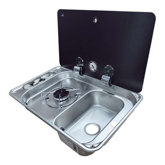
ATTENTION! The appliance is equipped with a glass lid. Glass lids can shatter if overheated or struck by sharp objects. Always open the lid before lighting any burner, making sure to switch off the burners and let them cool off a few minutes before reclosing the glass lid at the end of each operating cycle. -
Page 14: Identification Of The Appliance
GAS HOB UNITS COMBINED WITH RECESSED SINK ▪ FL series ▪ Do not heat empty pans or without a sufficient amount of cooking fluid. ▪ Do not expose the appliance to air draughts. The burners could go out. ▪ Do not force the knobs if blocked. Contact the Technical Assistance Service. ▪... -
Page 15: Reception Of The Appliance
INSTALLAZIONE-USO-MANUTENZIONE MANUALE DI ISTRUZIONI INSTALLAZIONE-USO-MANUTENZIONE MANUALE DI ISTRUZIONI INSTALLAZIONE-USO-MANUTENZIONE MANUALE DI ISTRUZIONI INSTALLAZIONE-USO-MANUTENZIONE serie FL CAN S.r.l. Via Nazionale 65, 25080 - Puegnago del Garda (BS) ITALY T. +39 0365 555909 F. +39 0365 651822 info@cansrl.com www.cansrl.com CONTROL AND HANDLING Upon reception of the appliance, proceed to unpack it. -
Page 16: Instructions For The Installer
INSTRUCTIONS FOR THE INSTALLER ATTENTION! Installation and all the interventions on the appliance described in this instruction manual must be carried out by qualified technical personnel and in compliance with standards in force. ATTENTION! The gas connection systems and the installation rooms must be suitable and meet the safety standards in force in the Country of use. -
Page 17: Installation On Support Structure
ATTENTION! The appliance must be installed in a room without air draughts which can have a negative effect on combustion. The chosen installation position must also prevent the accumulation of unburnt gases. -
Page 18: Safety Distances
1. FL1323 Remember to prepare adequate holes in the FL1324 furniture for passage of the gas pipe, water pipes FL1400 and electrical power of the appliance, if present. FL1401 FL1402 FL1410 FL1765... -
Page 19: Positioning The Appliance
POSITIONING THE APPLIANCE Proceed as follows to position the appliance on the support structure: step action Position the gasket (sold separately) on the edges of the metal moulding or sealant paste (if present). Position appliance on the recessed hole and push it onto the support structure. Secure the appliance using the fixing screws provided in the specific kit and screw them into the holes made at the four corners of the metal moulding. -
Page 20: Gas Connection
(Please note: this valve must always be shut during installation and maintenance on the appliance). -
Page 21: Gas Connection Procedure
12V and in direct current (DC) is strictly prohibited. 1 Power cable positive pole Any other connection can pose a severe 2 Power cable negative pole 3 Connection cable generator danger for the user of the appliance and... -
Page 22: Troubleshooting After Installation
GAS HOB UNITS COMBINED WITH RECESSED SINK ▪ FL series TROUBLESHOOTING AFTER INSTALLATION If the appliance does not work properly after installation, perform the controls in the table. problem possible solutions Check that the gas cock is completely open. Check that the fuel supply circuit has appropriate flow rate. Check that the burner spreaders and relative caps are positioned correctly and free The gas flow from obstructions. -
Page 23: Description
INSTRUCTIONS FOR USE DESCRIPTION See the exploded drawings on the following pages for the position of the components listed in the table. component Single wire pan support Ring for glass lid Glass lid Hinge for glass lid Plastic cap Silent block for resting lid Fixing screws cap Fixing screws for moulding CE label... - Page 24 GAS HOB UNITS COMBINED WITH RECESSED SINK ▪ FL series TYPE FL13XX detail A detail B detail C Fixing kit detail A detail B detail C...
- Page 25 TYPE FL14XX detail C detail A detail B Fixing kit detail A detail C detail B ▪ Installation, use and maintenance instruction manual Ed. 05/2018 Rev. 00...
- Page 26 GAS HOB UNITS COMBINED WITH RECESSED SINK ▪ FL series TYPE FL17XX detail A detail B detail C detail A detail B Fixing kit detail C...
-
Page 27: Safety Warnings During Use
▪ Switch off the burner after each use. ▪ Do not set or keep flammable liquids or materials or objects which can easily catch fire on the appliance or in its immediate vicinity. ▪ Do not place hot pans on the controls. -
Page 28: Lighting The Burners
Before use, make sure that the burner spreaders, caps and pan holders are positioned properly. burner spreader positioning The matching burner is indicated on each knob. The burner can be lit: ▪ manually using the external igniter (on STD versions), ▪... -
Page 29: Adjusting The Flame
To adjust the flame, turn the knob to the desired position (MIN or MAX). The knob can also be placed in the middle, between the maximum and minimum position. Do not place the knob between the maximum and “off” position. -
Page 30: Switching Off The Burner
Do not try to repair or modify the appliance. CAN S.r.l. will give you the maximum collaboration and assistance should any technical or other type of problems arise on any of its products. -
Page 31: Maintenance And Cleaning
Remove the components from their housing and wash them with warm water and dishwashing soap. Stubborn filth on the enamelled components can be removed using a slightly abrasive sponge and a degreaser, taking BURNER SPREADER/CAPS care not to damage the surfaces. -
Page 32: Long Idle Periods
GAS HOB UNITS COMBINED WITH RECESSED SINK ▪ FL series After cleaning, make sure that the pan holders have been put back in place correctly, paying attention not to invert them or couple them to different burners. The pan holders must always be stable and sit without rocking on the hob unit or be set firmly inside the specific fixing seats. -
Page 33: Spare Parts - Fl13Xx
SPARE PARTS ATTENTION! Use only original spare parts. The use of components other than those supplied by the Manufacturer terminates the Warranty and could cause personal harm or damage the appliance. ATTENTION! Parts must be replaced safely by authorised and qualified personnel. To make it easier to recognise the spare parts, read the tables below together with the exploded drawings shown in paragraph "Description". -
Page 34: Spare Parts - Fl14Xx
3000411 LH glass - FL1401 - FL1402 3000072 High rubber bushing for pan holders 3000401 Single wire enamelled pan support Ø 4,8 - FL1400 - FL1401 - FL1402 - FL1410 3000454 Silentblock Ø 15 4000026 2nd series lid stud bolt... -
Page 35: Spare Parts - Fl17Xx
SPARE PARTS - FL17XX The column "Pos." refers to the exploded drawing "type FL17XX" on page 26. PZ VERSION - PIEZOELECTRIC LIGHTING part number component 2000008 Hinge for glass lids 3000078 Single glass for FL1770 - FL1780 3000447 LH glass for FL1765 3000448 RH glass for FL1765 3000450...
Need help?
Do you have a question about the FL1400 and is the answer not in the manual?
Questions and answers