Advertisement
Quick Links
WARNINGS AND CAUTIONS:
• To be installed and/or used in accordance with appropriate electrical codes and regulations.
• If you are unsure about any part of these instructions, consult an electrician.
• WSS10-GDx products do not require a neutral wire, there is a minimum load requirement of 25 watts for these products.
Description
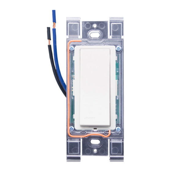
Cat. No. WSS10 is the receiver switch. This switch has a single switch pad that
toggles the relay and its corresponding load, ON and OFF. If the relay is OFF, the
relay will turn ON when the push-button is pressed, and vice-versa. The Indicator
LED will blink Red when a flag/packet is received from the sensor or remote switch.
NOTE: the no-neutral version has a minimum load requirement of 25 watts.
Cat. No. WSCxx is the sensor(s). The Sensor Unit sends a flag/packet with the
presence of motion to the receiver switch which then keeps the load ON. In the
absence of motion, the Sensor Unit will stop sending flag/packets to the receiver
switch; when the receiver switch no longer receives a packet, the Time Out will
start, then time-out and turn the relay OFF. Time Delay starts as of the last motion
detected in the space. The Motion Indicator LED will blink Red (1 blink per minute)
every time motion is detected, sending a flag/packet to the receiver. The LED on
the WSS10 receiver will blink Red, acknowledging the reception of a flag/packet.
WSCxx & WSS10 (together): In Manual-On/Auto-Off mode, the button must
•
be pressed to turn the lights ON. In the absence of flags/packets sent from the
sensor, the receiver switch will Time-Out and turn the lights OFF.
•
WSCxx & WSS10 (together): In Auto-On/Auto-Off mode, the sensor will send a
flag/packet to the receiver to turn the lights ON. In the absence of flags/packets
sent from the sensor, the receiver switch will Time-Out and turn the lights OFF.
NOTE: The sensor must sense motion and send a packet to start the time delay
and enable Auto-Off.
•
WSCxx & WSS10 (together): Allow the 30 second vacancy confirmation
feature which exists to turn the relay back ON in case of false OFF.
Self Powered Products: The sensor and remote switch are self powered devices
using EnOcean technology.
•
The Sensor utilizes a solar panel which powers the sensor from the rooms
ambient light. The sensor will start to function within a minute of exposure to
light. The total charge time for the sensor will vary depending on intensity of
light and length of exposure to light. The minimum light requirement for the
sensor is 40LUX (4FC).
•
The remote switch utilizes kinetic energy from the mechanical switch when
pushing the pad. This friction then stores enough energy to transmit another
signal on the next press action of the pad, tested over 50,000 cycles.
Battery option: The use of (3) AAA batteries (not included) is not required but can
be used in areas where no light is expected for long periods of time.
Low Voltage option: The 5-24VDC connection, is provided and recommended
when used in areas where no light is expected for long periods of time.
Tools needed
Slotted/Phillips Screwdriver
Electrical Tape
Pliers
Cutters
Ruler
Wire Nuts
Changing the color of your Switch
Color change options are available from Leviton, consult you local Leviton
Distributor. To change color of frame, proceed as follows:
Push in side at
tab to release
Incandescent: 800W @ 120V – Ballast: 1200VA @ 120V, 2700VA @ 277V
Installation
√
NOTE: Use check boxes
when Steps are completed.
WARNING:
Step 1
TO AVOID FIRE SHOCK OR DEATH; TURN
OFF POWER at circuit breaker or fuse and test that power is
off before wiring!
Identifying your wiring application
Step 2
(most common):
Single Pole
NOTE: If the wiring in your
wall box does not resemble
1. Line
this configuration, consult an
2. Neutral
electrician.
3. Ground
4. Load
Single Pole Wiring Application:
Step 3
•
WSS10 Receiver Control Switch is only
intended as a Single Pole device.
Multiple Location Wiring Application:
•
WSS0S Wireless Remote Switch can be used for additional
switches (3-way and 4-way), no wires necessary
Black wire (BK)
WIRING SWITCH:
Connect wires per WIRING DIAGRAM
below as follows:
•
Connect (Hot) wire from wall box to
black wire on switch.
•
Connect (Load) wire in wall box to
blue wire on switch.
•
Connect (Neutral) wire in wall box to
white wire on switch.
NOTE: For No Neutral model, white
Pencil
wire will not be available (Figure 2).
Figure 1 - With Neutral
(white wire)
Switch
WH
BK
BL
Black
Load
Line up tabs
White
and press in
side to attach
Single Pole (One Location)
Wireless Signal Receiver Switch
Cat. No. WSS10
120-277VAC, 50/60Hz, Motor: 1/4 HP @ 120V
INSTALLATION INSTRUCTIONS
WARNINGS AND CAUTIONS:
• Disconnect power at circuit breaker or fuse when servicing, installing or removing the WSS10.
• Use this device with copper or copper clad wire only.
• Recommended minimum wall box depth is 2-1/2".
Figure 2 - No Neutral
(no white wire)
Black
Load
White
Dip Switch Settings:
Step 4
NOTE: To access dip switch settings, lift up the bottom of the switch pad.
Auto-On / Auto-Off mode: Auto mode can be enabled using the dip switches, product
comes from the factory in Manual-On/Auto-Off.
Walk-through: can be used only in Auto-On mode and is recommended only when
using batteries or low voltage power connection.
2
1
Timeout: 2 (test), 10, 20, 30min; (Longer time delay is recommended for continuous
self powering of the sensor and to ensure packets are sent to the receiver switch).
3
4
ON
.
DIP SWITCH SETTINGS
Dip Switch
White wire (WH)
1
2
2 Min Time-Out
1
3
2
4
3
10 Min Time-Out
3
4
4
20 Min Time-Out
Blue wire (BL)
3
4
30 Min Time-Out
3
4
Hot (Black)
Factory settings:
WSS10: Manual On/AutoOff, Walk thru = disabled, Time delay = 10min.
WSCxx: Range (PIR sensitivity) = 75%
Line
Factory setting operation:
120-277VAC,
When entering the room, the wireless receiver control switch will need to be manually
50/60 Hz
turned ON. Once learned into the receiver switch, the Wireless occupancy sensor will
send flag/packets to the receiver switch, keeping the lights on until the room is vacant.
Once the sensor stops sending flag/packets, the receiver time out will start, then turn
Neutral (White)
the lights OFF after timeout period.
Time-Outs:
Switch
The Sensor has four time-out settings: 2 (test), 10, 20, or 30 min. (longer timeout
is recommended for self powering in dark spaces). The values of time-out is user
Hot (Black)
BK
selected through the use of the Dip Switch Settings. NOTE: Since the sensor is
only sending a packet every minute, the 2 minute time delay is not sufficient for
normal operation.
BL
Line
Walk-Through Time Delay:
120-277VAC,
The walk-through feature is only active in the Auto-On/Auto-Off mode with time
50/60 Hz
delay of 10, 20 or 30min, is useful when a room is momentarily occupied. With this
feature, the Sensor will turn the lights OFF shortly after the person leaves the room.
The walk-through feature works in the following manner: When a person enters the
Neutral (White)
room, the lights will turn ON. If the person leaves the room before the walk-through
time-out of 2.5 minutes, the Sensor will turn the lights OFF within 2.5 minutes of
no occupancy detected. If the room is occupied for longer than 2.5 minutes, the
Sensor will enter the Occupied Mode with the time-out duration specified by the
Dip Switch setting.
Step 5
1. Read all the Programming steps before taking any action to program the
receiver.
2. Enter Programming Mode by pressing and holding the switch button for 15
Seconds, The LED on the switch will begin flashing Amber slowly 1x per
second. This is the Mode Selection area of programming. Release the button.
3. Proceed to reading Rocker Mode, Momentary Mode, Toggle Mode and then
Scene Mode instructions.
Dip switches 1-4
NOTE: Amber flashing LED represents the Mode Selection Area of programming,
no buttons can be learned into a receiver with Amber flashing lights.
Rocker Mode Programming Instructions
(LED flashing Amber 1x per second)
1. Read all Rocker Mode programming steps before taking any action to program
receiver in Rocker Mode.
2. Upon entering programming, the device will automatically begin in
OFF Position
ON Position
Rocker Mode (Amber flash 1x per sec).
Auto-ON/Auto-Off
Manual-On/Auto-Off
3. To Learn a transmitter switch in Rocker Mode press and hold the button for 5
Walk Through Off
Walk Through On
seconds. The LED will change from Amber to Green* or Red** to signify you
OFF Position
ON Position
are now in the Learn area of programming. Release the button.
4. When learning a wireless Decora
X
-
-
one end of a switch rocker. When learning a transmitter other than a wireless
X
light switch, press the LEARN button on the transmitter (see appropriate
OFF Position
ON Position
transmitter instruction sheet). The LED will change/increase Green*
X
-
flashing and the load will stay ON for about 3 seconds indicating that the
-
X
receiver has stored the transmitter's unique ID in its memory.
OFF Position
ON Position
NOTE: Pressing the transmitter switch again will unlearn the unique ID. (refer
-
X
to below: Clear One Transmitter from Programming Mode).
X
-
NOTE: (If only one transmitter is desired then skip Step 5 and exit Learn
OFF Position
ON Position
Mode by following Step 7).
-
5. To program additional transmitters to communicate with this receiver in Rocker
X
-
X
Mode, wait until LED flashing resumes. Repeat the instructions in Step 4
until the unique IDs of all desired transmitters are stored in the Rocker Mode
memory of the receiver (up to 10).
6. To program a additional transmitters to communicate with this receiver
in another Mode, press the receiver button and return to Mode Selection
area (Amber LED flashing). The Amber LED will be flashing 1x per second
for Rocker Mode. Pressing the receiver switch button will advance the Amber
flashing to the next Programming Mode, Momentary Mode (Amber flash 2x per
second). Follow Steps 3 and 4 to program transmitters to Momentary Mode.
7. To exit Learn Mode, just wait; the receiver automatically exits Learn Mode after
30 seconds (indicated by the ceasing of the LED flashing).
PK-93664-10-00-0C
Programming Instructions:
®
style light switch to the receiver, press
Advertisement


Need help?
Do you have a question about the WSS10 and is the answer not in the manual?
Questions and answers