Table of Contents
Advertisement
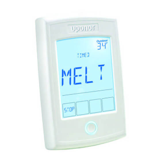
The Uponor Single-zone Snow Melt Control
(A3040654) is designed to operate hydronic
equipment to melt snow or ice from any
surface including driveways, walkways,
patios, business entrances, parking ramps,
loading docks, hospital entrances, helipads
or car wash bays.
The surface temperature for snow melting
is controlled automatically to reduce
operating energy costs. The control has
an automatic start and stop function when
used with the Pavement Snow and Ice
Sensor (A3040090).
Automatic start with a timed stop is
available when used with the Aerial
Snow Sensor (A3040095). The control
can operate a dedicated hydronic boiler.
Isolation relays are required to operate
line voltage pumps.
Single-zone snow
melt control
installation and
operation manual
Features
• Automatic snow/ice detection
• Supports both in-slab and retrofit aerial
snow sensors
• Mixing with modulating boiler
• Manual start with timer
• Warm weather shut down
• Cold weather cut out
• Idling
• Slab protection
• EconoMelt
• Manual override
• Exercising
• Alert output
Advertisement
Table of Contents

Related Manuals for Uponor A3040654


Summary of Contents for Uponor A3040654
- Page 1 Features The Uponor Single-zone Snow Melt Control (A3040654) is designed to operate hydronic • Automatic snow/ice detection equipment to melt snow or ice from any • Supports both in-slab and retrofit aerial surface including driveways, walkways,...
-
Page 2: Important Safety Information
Warning It is your responsibility to ensure that this control is safely installed according to all applicable codes and standards. Uponor is not responsible for damages resulting from improper installation and/or maintenance. To avoid serious personal injury and damage to the equipment: •... -
Page 3: Table Of Contents
Toolbox menu ........18 Technical data ........34 Getting started Congratulations on the purchase of your new Uponor Single-zone Snow Melt Control. This manual covers installation, programming, sequence of operation, instruction on testing, commissioning and troubleshooting. Single-zone snow melt control installation and operation manual | 3... -
Page 4: Installation
• Away from equipment, appliances or other Uponor recommends labeling each cable sources of electrical interference for easy identification. Strip all low-voltage wires to a length of ⅜" (9mm) to ensure •... -
Page 5: Sizing The Transformer
Pull 4-conductor, 18 AWG LVT cable up to • Supply sensor (if applicable) 500 feet (150m) for the Aerial Snow Sensor • On/off boiler (if applicable) (A3040095). • Modulating boiler 0-10 VDC or 4-20 mA Pull 5-conductor, 18 AWG LVT cable up to (if applicable) 500 feet (150m) for the Pavement Snow •... - Page 6 tN4 wiring center or zone manager Alert relay output Control wiring Alert relay output No power Yel Blu Red Out/ Aux Ht Yel B slab bret slab tN4 C R W tN4 C R W Zone 1 Zone 2 tN4 wiring center No power Alert or zone manager...
-
Page 7: Sensor Wiring
Sensor wiring Wiring the outdoor sensor • Connect 18 AWG or similar wire to the two Mounting the outdoor sensor terminals provided in the enclosure and Note: The temperature sensor (thermistor) run the wires from the outdoor sensor to is built into the sensor enclosure. the control. - Page 8 This delay increases around the sensor to reduce the effect of considerably when using mild steel air currents on the sensor measurement. (black iron) pipe. Uponor recommends using a temperature well for steel pipe Retaining of diameter greater than 1¼" (32mm).
-
Page 9: Testing The Sensor Wiring
Conduit connection First measure the temperature using the thermometer and then measure the The slab sensor and slab sensor resistance of the sensor at the control. The enclosure (sold separately) are specifically wires from the sensor must not be connected designed to mount onto a ⅜"... -
Page 10: Manual Override - Maximum Heat
Testing the relay outputs 5. Select the Maximum Heat Time after which the control resumes normal The control includes an Override menu to operation. check if the control’s relays are operating and that the control is wired correctly to the 6. -
Page 11: Manual Override - Off
Manual override — off 1. Press and hold the Home button for 3 seconds. The snow melting system can be manually 2. Press NEXT to navigate to the Override turned off and the control remains off until menu. manually changed back to Auto. This allows the installer or end user to permanently 3. -
Page 12: User Interface
User interface Display Touch to display run time, outdoor and slab temperature Status field Touch to quickly Operation field enter the view menu Touch to go to the next setting ENTER Touch to melt or stop Home button returns to the Home screen;... -
Page 13: Programmable Settings
Programmable settings Programming menus Setting items • Touch arrows to adjust the setting Press and hold the Home button for 3 if required. seconds to enter the programming menus. The control returns to the last programming • Touch NEXT ITEM to advance to the next menu previously used. -
Page 14: Access Levels And Access Level Lock
Access levels and access The control defaults to the User access level after 12 hours of operation. level lock To change to the Installer access level: The control is shipped pre-programmed with common settings. The control has an • In the Toolbox menu, locate Access. Installer access level that allows full access •... - Page 15 View menu (2 of 2) The View menu displays the current operating temperatures and status information of the system. Field Range Access Description Set to BOILER RATE — Shows the current firing rate of the modulating boiler. 0 to 100% Installer Conditions: Application Mode is set to Boil and Boiler Type is set to Mod (modulating...
-
Page 16: Set Temp Menu
Set Temp menu The Set Temp menu selects the operating temperatures of the snow melt system. Field Range Access Description Set to MELTING — Selects the desired surface 32 to 95ºF temperature of the snow melt surface (0.0 to 35.0ºC) User when melting. -
Page 17: Monitor Menu
Monitor menu The Monitor menu provides information about the system’s operation and performance. The Monitor menu is not available when the Application Mode is set to the Pavement Snow and Ice Sensor. Field Range Access Description Set to HEAT HOURS — Records the number of running 0 to 9999 User hours since the item was last reset. -
Page 18: Display Menu
Display menu The Display menu selects the temperature units and backlight options. Field Range Access Description Set to or ºC User UNITS — Selects Fahrenheit or Celsius as the Installer temperature units. Default = ºF BACKLIGHT — Selects how the display backlight operates. -
Page 19: Override Menu
Override menu The Override menu allows an operator to manually test each relay and manually start the system. Field Range Access Description Set to Hydronic MANUAL OVERRIDE — Manually overrides AUTO, the normal automatic operation of the control to HAND, test the equipment or operate the system at the MAX, maximum temperature limits. -
Page 20: System Menu
System menu The System menu provides settings on how to configure and operate the mechanical equipment. Field Range Access Description Set to APPLICATION MODE — Select the control PWM, BOIL, application mode. ELEC, Installer PWM = Hydronic pulse width modulation Default = BOIL = Hydronic boiler heats snow melting system ELEC = Electric snow melt... -
Page 21: Boiler Menu
Boiler menu The Boiler menu provides settings on how to configure and operate the boiler. Field Range Access Description Set to App mode = BOILER TYPE — Shows the type of boiler Boil connected to the control. MOD, MOD = Modulating boiler 1STG, Installer 1STG = Single one-stage on-off boiler... -
Page 22: Sequence Of Operation
Sequence of operation Snow melting overview In order to keep the slab surface at a constant temperature while operating, the A snow melting system can offer a safe, inner core of the slab must be heated above convenient and cost-effective way to the melt or idle temperature setting. -
Page 23: Manual Start And Timed Stop
Manual start and timed stop If a manual start has been provided and a sensor detects water, the control changes The snow melting system can be started from manual melt to automatic operation. manually by touching the Melt key on the The snow melting system will continue control display. -
Page 24: Automatic Start And Timed Stop
If the snow melting system is manually Pavement sensor detects water stopped, the sensor must fully dry Pavement sensor and slab dry and before it is able to detect a new snow ADD MELT time elapses fall and automatically start the snow Idle Timed melting system. -
Page 25: Additional Melting Time
When moisture is detected and both Touch MELT key the slab and outdoor temperatures are below the Melting setting, the Aerial Snow Sensor detects water control automatically starts the snow melting system. The snow melting Aerial Snow Sensor and slab dry and MELT time elapses Idle system operates to heat the slab... -
Page 26: Warm Weather Shut Down
A Snow-free Area Ratio of 0 is defined as Manual WWSD a system that allows snow accumulation. The control enters WWSD when the These systems operate the snow melting outdoor air temperature exceeds the system from a cold start resulting in the WWSD setting by 1ºF (0.5ºC) and when lowest energy consumption costs and the the slab temperature exceeds 34ºF (1ºC). -
Page 27: Away Key
Away key Disable the snow melting system with the Away Key. To turn on the Away Key, go to the Display menu. • Select AWAY KEY. • Select ON. To activate the Away Override (once the Away Key has been activated). •... -
Page 28: Electric Operation
Electric operation to prevent the slab temperature from overshooting. If no slab sensor is installed The control operates the heat relay on the heat relay remains on 100% of the time a 20-minute PWM cycle. The heat relay, until the Melt operation has completed. in turn, activates a line voltage electrical Idle operation is not available when a slab contactor to energize the electrical cable... - Page 29 Single stage on/off boiler (1STG) For commercial boilers with a mod motor, set the motor speed according to the time The control turns the heat relay on or off required by the mod motor to travel from the to fire the boiler in order to maintain the closed to the open position.
-
Page 30: Exercising
Exercising local error code. The Alert Relay is connected to the input power R and provides a 24 VAC In a hydronic snow melting system, the powered signal when closed. An isolation control operates the system pump every relay may be installed if a dry contact switch three days to prevent pump seizure. - Page 31 Error messages Field Description MAXIMUM MELT TIME ERROR — The control has operated in melting for the time set by Maximum Melt Days setting located in the System menu. This error is usually created when there is a mechanical system failure resulting in the snow melt slab not heating correctly.
-
Page 32: Symptoms And Solutions
Symptoms and solutions Symptom Look for… Corrective action LCD display is off Power to control Use electrical meter to measure 24 VAC voltage on input power R and C terminals. System pump Display shows idle Idle operation requires that the system pump operate always on continuously while below the melting temperature setting. -
Page 33: Job Record
Job record Set Temp menu settings Boiler menu settings Item Item Setting Setting Melting Boiler type Idling Boiler modulation type Manual melt run time Boiler minimum modulation Additional melt time Boiler modulation Water sensitivity delay WWSD Boiler motor speed CWCO Boiler differential Boiler minimum System menu settings... -
Page 34: Technical Data
Technical data Control Microprocessor control; not a safety (limit) control Packaged weight 1.3 lb. (590 g) Dimensions 5" H x 3¼" W x ⁄ " D (127mm x 82mm x 23mm) Enclosure White PVC plastic, NEMA type 1 -4 to 122ºF (-20 to 50ºC), < 90% RH non-condensing, outdoor use permitted Ambient conditions when installed inside a NEMA 3 enclosure Power supply... - Page 35 Single-zone snow melt control installation and operation manual | 35...
- Page 36 Uponor Inc. Uponor Ltd. 5925 148th Street West 6510 Kennedy Road Apple Valley, MN 55124 Mississauga, ON L5T 2X4 CANADA T 800.321.4739 T 888.994.7726 F 952.891.2008 F 800.638.9517 uponorpro.com SnMltControl_InstallOperMan_70162_0817, Copyright © 2017 Uponor. Printed in the United States.
Need help?
Do you have a question about the A3040654 and is the answer not in the manual?
Questions and answers