Assa Abloy SARGENT IN120 Installation Instructions Manual
Wifi mortise lock
Hide thumbs
Also See for SARGENT IN120:
- Installation instructions manual (32 pages) ,
- Quick start manual (3 pages) ,
- Installation instructions manual (44 pages)
Table of Contents
Advertisement
Quick Links
Advertisement
Table of Contents

Related Manuals for Assa Abloy SARGENT IN120


Summary of Contents for Assa Abloy SARGENT IN120
-
Page 1: Installation Instructions
IN120 WiFi Mortise Lock Installation Instructions A8151F 04/16 Copyright 2016, Sargent Manufacturing Company, an ASSA ABLOY Group company. All rights reserved. Reproduction in whole or in part without the express written permission of Sargent Manufacturing Company is prohibited. -
Page 3: Table Of Contents
System Overview ..............4 Parts Breakdown ..............5 Lock Installation ..............7 Operational Check ..............21 Changes or modifications to this device not expressly approved by ASSA ABLOY Warning could void the user’s authority to operate the equipment. FCC: This equipment has been tested and found to comply with the limits for a Class B digital device, pursuant to Part 15 of the FCC Rules. -
Page 4: General Description
UL 294 Access Control Ratings: Destructive Attack Level 1 Line Security Level 1 Endurance Level 4 *For specific security information, please contact your local ASSA ABLOY Door Security Solutions sales consultant or Standby Power Level 1 call 800-810-WIRE. 1-800-810-WIRE • www.sargentlock.com • A8151F... -
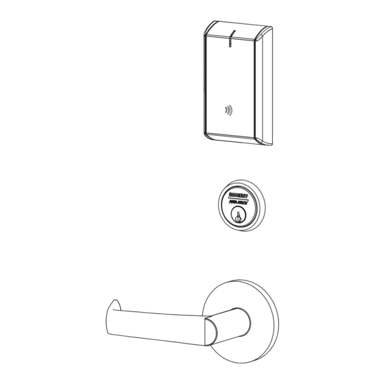
Page 5: Parts Breakdown
IN120 Mortise Lock Parts Breakdown PART NO./ORDER ITEM DESCRIPTION QTY. STRING IN-120-EM01-[B]IP-B Reader assembly - black plastic IN-120-EM01-[B]IP-W Reader assembly - white plastic IN-120-EM01-[B]IP-MB-xxx** Reader assembly - black plastic with metal trim IN-120-EM01-[B]IP-MW-xxx** Reader assembly - white plastic with metal trim IN-120-EM01-[B]IPS-B Reader assembly - black plastic IN-120-EM01-[B]IPS-W... - Page 6 IN120 Mortise Lock Parts Breakdown (Continued) PART NO/ORDER ITEM DESCRIPTION STRING Consult Factory #41 Mortise cylinder Consult Factory Cylinder Rosette IN-120-7976-hand-fin Lock body with deadbolt with cylinder IN-120-7977-hand-fin Lock body with deadbolt without cylinder IN-120-7978-hand-fin Lock body without deadbolt with cylinder IN-120-7979-hand-fin Lock body without deadbolt without cylinder IN-120-82276-hand-fin*...
-
Page 7: Lock Installation
IN120 Mortise Lock Lock Installation 1 Prepare Door A. Verify Hand and Bevel of Door Stand on outside of locked door when determining door hand. LHRB RHRB Left Hand Left Hand Right Hand Right Hand Hinges Left Reverse Bevel Hinges Right Reverse Bevel Open Inward Hinges Left... - Page 8 IN120 Mortise Lock 2A Prepare 7900 Lock Body* *If 7900 is type of lock being installed 1. Reverse Lock Hand (If Required) Red surface of locking piece must face the outside (locked side) of door. To rotate locking piece (Fig. 2A1): a.
- Page 9 IN120 Mortise Lock 2B Prepare 8200 Lock Body* *If 8200 is type of lock being installed 1. Reverse Lock Hand Red surface of locking piece must face the outside/locked side of door. To rotate locking Right Hand piece (Fig. 2B1): Lock Shown a.
- Page 10 IN120 Mortise Lock 3 Install Door Position Switch (DPS) 1. Push wires through raceway toward lock prep. 2. Push DPS firmly into place by hand. Note: DO NOT TAP SWITCH WITH ANY TOOL. 3. Install magnet into door frame. Push firmly into place by hand. See instruction A7983.
- Page 11 IN120 Mortise Lock 4 Install Lock Body Note: Do not pull the lock into the pocket using the harness alone. Ensure that the wire harness is not pinched between the lock and the mortise pocket. 1. Feed the wire harness into the mortise pocket and through inside preparation hole as depicted in Figure 4.
- Page 12 IN120 Mortise Lock 5 Outside Cylinder Installation 1. Slide the spring and the rosette onto the cylinder. 2. Rotate the cylinder into cylinder hole with fingers. 3. Insert key 75% of the way and utilize the key to rotate the cylinder into the rest of the cylinder hole.
- Page 13 IN120 Mortise Lock 6 Assemble Outside Trim 1. With outside lever horizontal, insert the mounting posts through outside of door and lock body. Make certain the lever spindle is properly engaged inside the lock body (Fig 6A). 2. On the inside of the door, insert spindle into square hole of mortise lock (Fig 6B). 3.
- Page 14 IN120 Mortise Lock 7 Install Inside Rose and Inside Lever Assembly 1. Place inside rose flush against door surface and rotate first counter-clockwise to seat the threads, then clockwise to securely tighten. 2. Slide lever onto spindle until fully seated. Be sure handle is horizontal and facing the hinge side of the door.
- Page 15 IN120 Mortise Lock 8 Install Thumb Turn 1. Insert thumb turn into preparation hole and engage slot in lock body. 2. Orient mounting plate so screw hole is vertical (aligned with preparation holes). 3. Secure plate with Phillips screw provided. 4.
- Page 16 IN120 Mortise Lock 10 Outside Reader Installation 1. Orient the reader so the LED lens is at the top. 2. Feed the reader harness through the door (from outside to inside). 3. Install the reader to the outside of door by aligning the mounting posts with the door preparation holes. Hold the reader flush against door while ensuring proper alignment.
- Page 17 IN120 Mortise Lock 10 Outside Reader Installation (Continued) 4. Next feed the cables/connectors through the inside mounting assembly (and gasket if required*). 5. Secure the mounting assembly while ensuring proper alignment of outside reader and tighten the (2) through-bolts on the inside of the door to secure the reader (Fig. 10B). IMPORTANT: Do not run wires through bottom hole in plate (Fig.
- Page 18 IN120 Mortise Lock 10 Outside Reader Installation (Continued) DPS (4-pin) 9-24VDC Installation of Connectors Power* CAUTION - Do not touch or allow debris to enter connector contacts. Secure the following connectors to their respective terminals (Fig. 10C, D): A. Secure the 4-pin DPS connector. B.
- Page 19 IN120 Mortise Lock 11 Install Inside Module Component Assembly 1. Insert top tabs of controller into slots on mounting plate (Fig. 11). 2. Ensure proper alignment of board-to-board connectors while pivoting bottom of controller toward door until tab on bottom snaps securely into place on mounting plate.
-
Page 20: Battery Installation
IN120 Mortise Lock 12 Battery Installation Before installing batteries for the first time: Remove pull tab from its position beneath the coin cell by pulling on tab in direction of arrows printed on tab (Fig. 12). 1. Place (6) “AA” alkaline batteries in the compartment, being AA Batteries (6) careful to align polarity properly. -
Page 21: Operational Check
IN120 Mortise Lock Operational Check For 7976-, 7978-, 82276- and 82278-function mortise locks with cylinders: 1. Insert key into cylinder and rotate. There should be no friction against lock case, wire harness or any other obstructions. 2. Check that the key retracts the latch: the key should rotate freely. - Page 22 IN120 Mortise Lock Notes 1-800-810-WIRE • www.sargentlock.com • A8151F...
- Page 24 The company’s customer base includes commercial construction, institutional, and industrial markets. Copyright © 2016, Sargent Manufacturing Company, an ASSA ABLOY Group company. All rights reserved. Reproduction in whole or in part without the express written permission of Sargent Manufacturing Company is prohibited.
Need help?
Do you have a question about the SARGENT IN120 and is the answer not in the manual?
Questions and answers