Table of Contents

Related Manuals for SteamOvap IER-04 Series

Summary of Contents for SteamOvap IER-04 Series
- Page 1 ELECTRIC RESISTIVE STEAM HUMIDIFIER Installation and Operation Manual Please read and save this manual steamOvap technologies inc, 9495 Charles de la Tour, Montreal, Qc, H4N 1M5, Canada Tel.: 1-844-357-4477 • www.steamOvap.com Rev.180401...
-
Page 3: Introduction
IOM are observed. Any other use or operation outside the above design scope without written authorization from steamOvap may lead to trouble and hazardous conditions and will void warranty. No alteration or modification to the humidifier must be done without written authorization from steamOvap. -
Page 4: Table Of Contents
Table of content Introduction ....................3 Table of content ..................4 Safety warnings ..................5 Before to proceed to Installation ............... 6 IER Overview ................... 7 Installation overview ................10 Installation – step 1 IER Positioning & Mounting ........12 Installation –... -
Page 5: Safety Warnings
Risk of malfunction. Steam lines should not have any restriction or blockage that may cause a burst of pressure in the steam line. Others Risk of flooding. In order to avoid any risk of flooding steamOvap recommends a Hi limit humidity switch installed in the air duct downstream of the steam distribution ... -
Page 6: Before To Proceed To Installation
2. Verify that model of the humidifier matches the purchase order and that all accessories are included. 3. Any missing item should be reported as soon as possible to steamOvap or its representative and within 5 business days after receipt. -
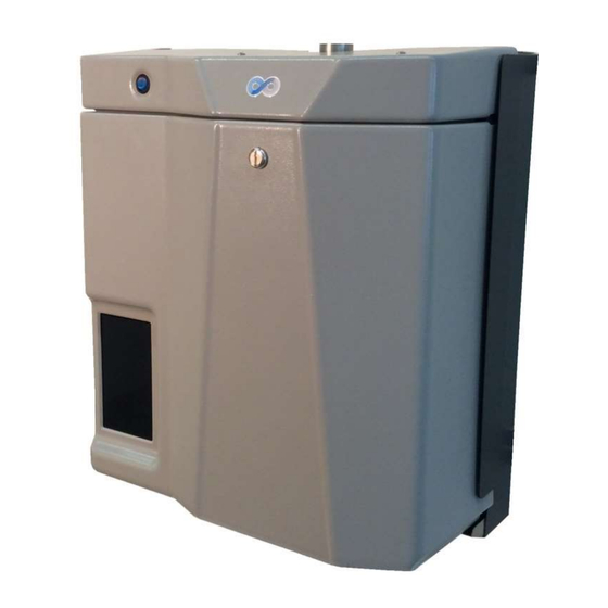
Page 7: Ier Overview
O V E R V I E W IER Overview IER electric steam humidifier Figure 1 – IER Overview IER product designation & name plate steamOvap technologies inc. Electric resistive steam humidifier IER12-240/1 MODEL YY-DDDXXX 12kW 240Vac POWER VOLTAGE CURRENT 44.2A... - Page 8 O V E R V I E W Model designation and options codification Type & Model Nominal Voltage Nb of Phase Options MB Mounting Bracket FS Floor Stand BC/MS BACnet MSTP BC/IP BACnet IP Mod Modbus IER 12 - 240 / 1 - MB IER electrical rating Steam Current...
- Page 9 O V E R V I E W IER Dimensions Figure 3 – IER Dimensions Steam Nb Cyl Nb Steam Dimensions Model Outlet + Ø Capacity + size weight 20in 23in 13in 55lb 10lb/h 1x 1.5po IER-04 small [DN40] [510mm] [585mm] [330mm] [25kg]...
-
Page 10: Installation Overview
section I N S T A L L A T I O N Installation overview General 1. Installation of this humidifier should be carried out by trained and qualified personnel. 2. Any work related to installation of this humidifier must comply with local code and regulation regarding safety and prevention of accidents. - Page 11 I N S T A L L A T I O N Installation steps : 1. Positioning & mounting of IER electric steam humidifier 2. Water supply installation 3. Drain installation 4. Steam line installation for duct humidification or Direct humidification in room 5.
-
Page 12: Installation - Step 1 Ier Positioning & Mounting
If local is subject to below freezing point temperature, activation of ant freezing function of the IER electric steam humidifier is required. For outdoor installation please contact your steamOvap representative to order and install special outdoor optional enclosure for IER. - Page 13 I N S T A L L A T I O N Clearances Figure 6 – minimum clearances Clearance guidelines There is no minimum clearance on both side of the IER humidifier, but it is a good practice to have a clearance of 4 to 8 in [100 to 200mm] for ease of installation and service Allow a minimum clearance of 24in [610mm] with floor to allow for proper drain slope and drain pipe column.
- Page 14 I N S T A L L A T I O N Clearances for IER with space blower Figure 7 – minimum clearances for SB Clearance guidelines There is no minimum clearance on both side of the Space blower, but it is a good practice to have a clearance of 4 to 8 in [100 to 200mm] for ease of installation and service Front clearance of 80in [2000mm] is required for steam absorption.
- Page 15 I N S T A L L A T I O N Mounting holes positions & weight Figure 8 mounting holes single module Figure 9 – mounting holes double module (IER 04 to 31) (IER44 & 62) Mounting holes positions (in) [mm] Model IER04 to 09 2 [51]...
- Page 16 IER electric steam humidifier. In case, the wall is not solid enough to support operating weight of IER electric steam humidifier, install it on a floor stand (FS option is available to your steamOvap representative). 2. Mark the wall or support according to the above holes location, and drill 4 holes to the wall or support as per the size of anchors and/or screws.
- Page 17 IER electric steam humidifier. In case, the wall is not solid enough to support operating weight of IER electric steam humidifier, install it on a floor stand (FS option is available to your steamOvap representative). 3. Mark the wall or support according to the above holes location, Drill holes to the wall or support to attach the mounting bracket to the wall as per the size of anchors and/or screws.
-
Page 18: Installation - Step 2 Water Supply Installation
I N S T A L L A T I O N Installation – step 2 Water supply installation Water supply specification & quality: Water supply pressure: 15 to 80PSI [1 to 5bar] Water supply temperature: 37 to 105°F [3 to 40°C] IER electric steam humidifier can accept a wide range of water quality. -
Page 19: Installation - Step 3 Drain Installation
I N S T A L L A T I O N Water supply connection: 1. Install a manual; shut off valve on the water main line. 2. If IER humidifier is supplied with tap water it is recommended to install a 10µ sediment filter on the line. -
Page 20: Installation - Step 4 Steam Line Installation
I N S T A L L A T I O N Installation – step 4 Steam line installation Duct humidification Horizontal duct Figure 13 – SRS & SRSX installation – no dedicated condensate return line Figure 14 – SRC & SRCX installation – with dedicated condensate return line to IER... - Page 21 I N S T A L L A T I O N Installation steps : 1. Positioning & mounting of SR (S, C, SX or CX) steam ramp to the ventilation duct wall by using metal screw 2. Install the steam hose or rigid steam pipe between the IER steam humidifier and the steam ramp.
- Page 22 I N S T A L L A T I O N Steam ramp description SRS - Steam ramp SRC - Steam ramp without dedicated condensate return with dedicated condensate return Figure 20 – SRC Figure 16 – SRS Avoid any possible trouble due to condensate Simpler to install, but not recommended flow against the steam flow inside steam pipe when large quantity of condensate is...
- Page 23 I N S T A L L A T I O N Minimum distances for SRS & SRSX Figure 24 – SRS & SRSX minimum distances In order to avoid condensing on the duct surface or on ramps, steamOvap recommends the following minimum distances: ht(min) Minimum height distance between end of top ramp (#3) and top of the duct.
- Page 24 I N S T A L L A T I O N Minimum distances for SRC & SRCX Figure 25 – SRC & SRCX minimum distances In order to avoid condensing on the duct surface or on ramps, steamOvap recommends the following minimum distances: ht(min) Minimum height distance between end of top ramp (#3) and top of the duct.
- Page 25 I N S T A L L A T I O N steamOsorb installation Figure 26– steamOsorb multiramp installation Figure 27– steam ramp profile and outlets position See detail drawing for complete dimensions And refer to steamOsorb IOM for installation steps.
-
Page 26: Installation - Step 5 Power Supply Installation
I N S T A L L A T I O N Installation – step 5 Power supply installation Electrical Warning Risk of electric shock. Disconnect power supply before installation or service. Power supply connexion must be done by a trained and qualified electrician. Any work related to power supply installation of this humidifier must comply with local code and regulation regarding safety and prevention of accidents. - Page 27 I N S T A L L A T I O N IER electrical rating Steam Current Model Power Capacity 208Vac/1p 240Vac/1p 208Vac/3p 480Vac/3p 600Vac/3p 10lb/h IER-04 3.3kW 16.0A 13.9A 9.3A 4.0A 3.2A [4.5kg/h] 15lb/h IER-05 5.0kW 24.0A 20.8A 13.9A 6.0A 4.8A [6.8kg/h]...
-
Page 28: Installation - Step 6 Control Installation
I N S T A L L A T I O N Installation – step 6 Control installation General guidelines for control installation It is a good practice to install the following safety controls: An air proving switch (APS) in the same duct as the humidifier’s steam ramp so that it can prevent humidifier from producing steam in case there is no air flow. - Page 29 I N S T A L L A T I O N Figure 30 – Control connection Admissible control signal Control Admissible signals External analog signal for 0-10Vdc, 2-10Vdc, 4-20mA demand On-Off external signal Dry contact Proportional RH% or 0-10Vdc, 2-10Vdc, 4-20mA temperature sensor Installation steps : 1.
-
Page 30: Verification Before Start-Up
Risk of flooding. In order to avoid any risk of flooding steamOvap recommends a Hi limit humidity switch installation in the air duct downstream of the steam distribution ramp. - Page 31 I N S T A L L A T I O N Power supply o Verify that power supply wires have been connected to main terminal and ensure that all wires are safely tightened. Ensure that an all pole disconnecting device with fuses is installed and easily accessible.
-
Page 32: Configuration & Operation
C O N F I G U R A T I O N & O P E R A T I O N section Configuration & Operation Dashboard screen Dashboard screen is also the main/home screen Figure 31 – Dashboard screen... - Page 33 C O N F I G U R A T I O N & O P E R A T I O N Overview screen Overview screen gives all information on internal sensors and control settings and allow ordering a drain for service Figure 32 –...
- Page 34 C O N F I G U R A T I O N & O P E R A T I O N Icon status An icon status located at the right hand side in the footer of the screen indicate the status of the iER IER is OK and in operation or stand by.
- Page 35 C O N F I G U R A T I O N & O P E R A T I O N Control Setting screen Control setting screen allows user (control engineer) to set signal and parameters to control the IER humidifier.
- Page 36 C O N F I G U R A T I O N & O P E R A T I O N Control setting / control config Figure 34 – Control setting/control config screen...
- Page 37 C O N F I G U R A T I O N & O P E R A T I O N Control setting / setpoint & output config Figure 35 – Control setting/setpoint config screen...
- Page 38 C O N F I G U R A T I O N & O P E R A T I O N Control setting / Hi Limit config Figure 36 – Control setting/Hi Limit config screen...
- Page 39 C O N F I G U R A T I O N & O P E R A T I O N Humidifier setting screen Humidifier setting screen allows user (mechanical contractor) to set humidifier parameters. Access to this screen can be restricted with password. In this case password is 7030 Humidifier setting / setting 1 Figure 37 –...
- Page 40 C O N F I G U R A T I O N & O P E R A T I O N Humidifier setting / setting 2 Figure 38 – Humidifier setting/setting 2 screen...
- Page 41 C O N F I G U R A T I O N & O P E R A T I O N Humidifier setting / Main setting Figure 39 – Humidifier setting/setting 1 screen...
-
Page 42: List Of Alarms
C O N F I G U R A T I O N & O P E R A T I O N List of alarms In case of alarm, the status icon located at the right hand side in the bottom footer of the screen can be either: Alarm level 1, critical alarm will stop operation of IER, if latched will need manual reset by service technician. -
Page 43: Warranty
90 days, whichever is longer. No liability whatsoever shall be attached to steamOvap until said products have been paid for in full and then said liability shall be limited to the original purchase price for the product. Any further warranty must be in writing, signed by an officer of steamOvap. - Page 44 2018 steamOvap technologies inc. 9495 Charles de la Tour Montreal, Qc, H4N 1M5 Canada Tel.: +1-844-357-4477 info@steamOvap.com www.steamOvap.com Information contained in this manual is subject to change without notice. To obtain the latest technical information visit our website at www.steamOvap.com...
Need help?
Do you have a question about the IER-04 Series and is the answer not in the manual?
Questions and answers