Mitsubishi Electric MLZ-KP25VF Installation Manual
Ceiling cassette type air conditioners
Hide thumbs
Also See for MLZ-KP25VF:
- Operating instructions manual (208 pages) ,
- Service manual (43 pages) ,
- Installation manual (12 pages)
Table of Contents
Advertisement
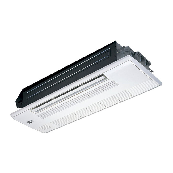
CEILING CASSETTE TYPE AIR CONDITIONERS
MLZ-KP25VF
MLZ-KP35VF
REFRIGERANT
R32/R410A
MLZ-KP50VF
INSTALLATION MANUAL
INSTALLATIONSANLEITUNG
NOTICE D'INSTALLATION
INSTALLATIEHANDLEIDING
MANUAL DE INSTALACIÓN
MANUALE PER L'INSTALLAZIONE
ΕΓΧΕΙΡΙΔΙΟ ΕΓΚΑΤΑΣΤΑΣΗΣ
MANUAL DE INSTALAÇÃO
INSTALLATIONSHÅNDBOG
INSTALLATIONSANVISNING
TESİS ETME KILAVUZU
РЪКОВОДСТВО ЗА МОНТАЖ
INSTRUKCJA MONTAŻU
INSTALLASJONSHÅNDBOK
ASENNUSOPAS
INSTALAČNÍ PŘÍRUČKA
NÁVOD NA INŠTALÁCIU
TELEPÍTÉSI KÉZIKÖNYV
NAMESTITVENI PRIROČNIK
MANUAL DE INSTALARE
PAIGALDUSJUHEND
MONTĀŽAS ROKASGRĀMATA
MONTAVIMO VADOVAS
PRIRUČNIK ZA POSTAVLJANJE
UPUTSTVO ZA UGRADNJU
English
Deutsch
Français
Nederlands
Español
Italiano
Ελληνικά
Português
Dansk
Svenska
Türkçe
Български
Polski
Norsk
Suomi
Čeština
Slovenčina
Magyar
Slovenščina
Română
Eesti
Latviski
Lietuviškai
Hrvatski
Srpski
Advertisement
Table of Contents

Related Manuals for Mitsubishi Electric MLZ-KP25VF


Summary of Contents for Mitsubishi Electric MLZ-KP25VF
- Page 1 REFRIGERANT R32/R410A CEILING CASSETTE TYPE AIR CONDITIONERS MLZ-KP25VF MLZ-KP35VF MLZ-KP50VF English INSTALLATION MANUAL Deutsch INSTALLATIONSANLEITUNG Français NOTICE D’INSTALLATION Nederlands INSTALLATIEHANDLEIDING Español MANUAL DE INSTALACIÓN Italiano MANUALE PER L’INSTALLAZIONE Ελληνικά ΕΓΧΕΙΡΙΔΙΟ ΕΓΚΑΤΑΣΤΑΣΗΣ Português MANUAL DE INSTALAÇÃO Dansk INSTALLATIONSHÅNDBOG Svenska INSTALLATIONSANVISNING Türkçe TESİS ETME KILAVUZU...
-
Page 2: Table Of Contents
FOR INSTALLER Required Tools for Installation CONTENTS Phillips screwdriver Flare tool for R32, R410A Level Gauge manifold for R32, R410A 1. BEFORE INSTALLATION ..... 1 6. PUMPING DOWN ......10 Scale Vacuum pump for R32, R410A 2. INDOOR UNIT INSTALLATION .... 4 7. -
Page 3: Selecting The Installation Location
This manual only describes the installation of indoor unit. When installing the outdoor unit, refer to the installation manual of outdoor unit. CAUTION (Could lead to serious injury in particular environments when operated incorrectly.) I Install an earth leakage breaker depending on the I Do not touch the air inlet or the aluminum fins of I Do not operate the air conditioner during interior installation place. -
Page 4: Installation Diagram
1-4. INSTALLATION DIAGRAM Be sure to use wall hole sleeve to prevent indoor/outdoor connecting wire from contacting metal parts in the wall and to prevent damage by rodents in case the wall is hollow. Wall hole cover Indoor unit Seal the wall hole gap with putty Wall hole Fix the pipe to wall... -
Page 5: Indoor Unit Installation
2. INDOOR UNIT INSTALLATION 2-1. CEILING OPENINGS AND SUSPENSION BOLT Align center of ceiling INSTALLATION LOCATIONS opening and bolt distance • Install the indoor unit at least 2.2 m above floor or grade level. • For appliance not accessible to the general public. •... -
Page 6: Drain Piping
Unit suspension procedures Suspension bolt (M10) • Adjust the length of the bolt’s protrusion from the ceiling surface beforehand. • Check the pitch of the suspension bolt . (308 mm × 1051 mm) Nut with flange (M10) 1) Install special washer and their nuts onto the suspension bolt Special washer (with cushion, 4 pcs) - Page 7 • Connect drain pipe directly to drain piping connecting part (socket side) of Drain piping connecting part (with socket) Drain hose drain hose • Be sure to connect drain hose to the indoor unit side as shown in the illus- Drain hose connecting part Drain pipe tration on the right.
-
Page 8: Flaring Work And Pipe Connection
2-4. CONNECTING WIRES FOR INDOOR UNIT Indoor/outdoor unit 1) Remove electrical cover (1). connecting wire 2) Remove cord clamp. 3) Pass indoor/outdoor unit connecting wire process the end of the wire. 4) Loosen terminal screw, and connect first the earth wire, then indoor/outdoor unit connecting wire to the terminal block. -
Page 9: Flaring Work
3-2. FLARING WORK No good Good 1) Cut the copper pipe correctly with pipe cutter. (Fig. 1, 2) 90° 2) Completely remove all burrs from the cut cross section of pipe. (Fig. 3) Copper pipe • Put the end of the copper pipe to downward direction as you remove burrs in order to avoid to let burrs drop in the piping. -
Page 10: Test Run
4. TEST RUN 4-1. TEST RUN • Do not operate the unit for long periods at places such as building under con- struction. This may cause dust or odor to adhere to the unit. • Perform test run with the attendance of user, as much as possible. 1) Press the E.O. -
Page 11: Pumping Down
6. PUMPING DOWN Refer to the procedures indicated in the installation manual of the outdoor unit. WARNING When pumping down the refrigerant, stop the compressor before disconnecting the refrigerant pipes. The compressor may burst if air etc. get into it. 7. - Page 12 This product is designed and intended for use in the residential, commercial and light-industrial environment. HEAD OFFICE: TOKYO BUILDING, 2-7-3, MARUNOUCHI, CHIYODA-KU, TOKYO 100-8310, JAPAN RG79Y972H01...
Need help?
Do you have a question about the MLZ-KP25VF and is the answer not in the manual?
Questions and answers