Table of Contents
Advertisement
Quick Links
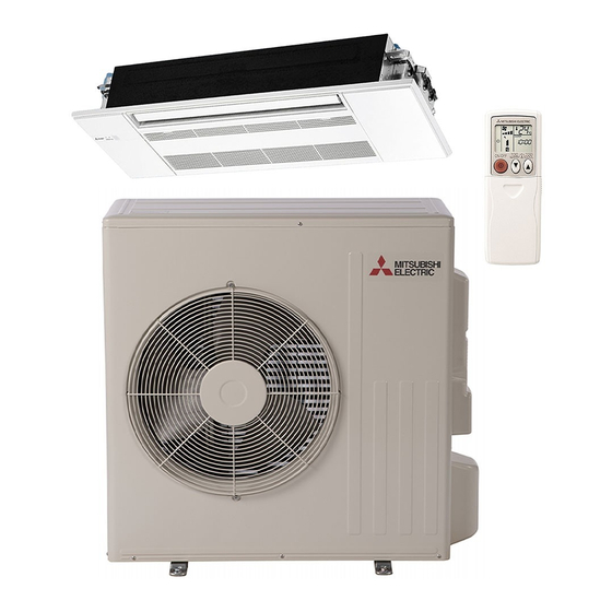
INDOOR UNIT
SERVICE MANUAL
Models
MLZ-KP09NA
MLZ-KP12NA
MLZ-KP18NA
MLZ-KP09NA2
-
U1
MLZ-KP12NA2
-
U1
MLZ-KP18NA2
-
U1
CONTENTS
1. TECHNICAL CHANGES ··································· 2
2. PART NAMES AND FUNCTIONS ····················· 3
3. SPECIFICATION ················································ 4
4. OUTLINES AND DIMENSIONS ························ 6
5. WIRING DIAGRAM ············································ 7
6. REFRIGERANT SYSTEM DIAGRAM ··············· 9
7. SERVICE FUNCTIONS ··································· 10
8. MICROPROCESSOR CONTROL ··················· 13
9. TROUBLESHOOTING ····································· 22
10. DISASSEMBLY INSTRUCTIONS ···················· 37
PARTS CATALOG (OBB802)
Revision B:
• MLZ-KP09/12/18NA2-
U1
OBH802 REVISED EDITION-A is void.
No. OBH802
REVISED EDITION-B
Outdoor unit service manual
MXZ-C NA, MXZ-C NAHZ Series
(OBH702, OCH573)
have been added.
-
U1
-
U1
-
U1
Advertisement
Table of Contents

Related Manuals for Mitsubishi Electric M Z-C NA Series


Summary of Contents for Mitsubishi Electric M Z-C NA Series
-
Page 1: Table Of Contents
Revision B: • MLZ-KP09/12/18NA2- have been added. OBH802 REVISED EDITION-A is void. INDOOR UNIT No. OBH802 REVISED EDITION-B SERVICE MANUAL Models MLZ-KP09NA MLZ-KP09NA2 MLZ-KP12NA MLZ-KP12NA2 MLZ-KP18NA MLZ-KP18NA2 Outdoor unit service manual MXZ-C NA, MXZ-C NAHZ Series (OBH702, OCH573) CONTENTS 1. TECHNICAL CHANGES ··································· 2 2. -
Page 2: Technical Changes
Use the specified refrigerant only Never use any refrigerant other than that specified. Doing so may cause a burst, an explosion, or fire when the unit is being used, serviced, or disposed of. Correct refrigerant is specified in the manuals and on the spec labels provided with our products. We will not be held responsible for mechanical failure, system malfunction, unit breakdown or accidents caused by failure to follow the instructions. -
Page 3: Part Names And Functions
PART NAMES AND FUNCTIONS INDOOR UNIT MLZ-KP09NA MLZ-KP12NA MLZ-KP18NA MLZ-KP09NA2 MLZ-KP12NA2 MLZ-KP18NA2 Horizontal vane Vertical vane Air inlet Intake grille Air outlet Air filter (Air purifying filter) Air cleaning filter (Anti-Allergy Enzyme filter, option) Display section Spec name plate Safety strings Open the display cover Remote control receiving section Emergency operation switch... -
Page 4: Specification
SPECIFICATION 1. Multi connection MLZ-KP09NA MLZ-KP12NA MLZ-KP18NA Indoor model MLZ-KP09NA2 MLZ-KP12NA2 MLZ-KP18NA2 208/230, 1, 60 Power supply V, phase, Hz Max. fuse size (time delay)/ Disconnect switch A COOL Dry 403 - 346 - 293 - 212 Airflow 311 - 283 - 254 - 212 332 - 297 - 258 - 212 (Wet) High - Med. - Page 5 3-1. OPERATING RANGE (1) POWER SUPPLY Rated voltage Guaranteed voltage (V) 208/230 V Min. 187 Max. 253 Indoor unit 1 phase 60 Hz (2) OPERATION *The operating range of the outdoor unit depends on the connected outdoor unit. Intake air temperature (°F) Mode Condition Indoor...
-
Page 6: Outlines And Dimensions
OUTLINES AND DIMENSIONS Unit: inch MLZ-KP09NA MLZ-KP12NA MLZ-KP18NA MLZ-KP09NA2 MLZ-KP12NA2 MLZ-KP18NA2 INDOOR UNIT OBH802B... -
Page 7: Wiring Diagram
WIRING DIAGRAM INDOOR UNIT MLZ-KP09NA- MLZ-KP12NA- CN302 CN301 DISP P.C.BOARD P.C.BOARD NOTES : NAME NAME SYMBOL SYMBOL 1.About the outdoor side electric wiring ROOM TEMP. refer to the outdoor unit electric wiring FAN MOTOR RT11 THERMISTOR diagram for servicing. HORIZONTAL COIL TEMP. - Page 8 MLZ-KP18NA- CN302 CN301 DISP P.C.BOARD P.C.BOARD NOTES : SYMBOL NAME SYMBOL NAME 1.About the outdoor side electric wiring ROOM TEMP. FAN MOTOR RT11 refer to the outdoor unit electric wiring THERMISTOR diagram for servicing. HORIZONTAL COIL TEMP. CN106 2.Use copper conductors only. RT12 VANE MOTOR THERMISTOR(MAIN1)
-
Page 9: Refrigerant System Diagram
REFRIGERANT SYSTEM DIAGRAM INDOOR UNIT MLZ-KP09NA MLZ-KP18NA Unit: inch(mm) MLZ-KP12NA MLZ-KP18NA2 MLZ-KP09NA2 MLZ-KP12NA2 Refrigerant pipe Ø3/8(Ø9.52) Refrigerant pipe Ø1/2(Ø12.7) (with heat insulator) (with heat insulator) Indoor coil Indoor coil thermistor thermistor Indoor Indoor RT12,RT14, heat heat RT12 (main) RT15 (main) exchanger exchanger Flared connection... -
Page 10: Service Functions
SERVICE FUNCTIONS MLZ-KP09NA MLZ-KP12NA MLZ-KP18NA MLZ-KP09NA2 MLZ-KP12NA2 MLZ-KP18NA2 7-1. TIMER SHORT MODE • For service, the following set time can be shortened by bridging the timer short mode point on the electronic control P.C. board. (Refer to 9-7.) • The set time for the ON/OFF timer can be reduced to 1 second for each minute. •... - Page 11 7-3. AUTO RESTART FUNCTION When the indoor unit is controlled with the remote controller, the operation mode, the set temperature, and the fan speed are memorized by the indoor electronic control P.C. board. “AUTO RESTART FUNCTION” automatically starts operation in the same mode just before the shutoff of the main power. Operation If the main power has been cut, the operation settings remain.
- Page 12 7-4. P.C. BOARD MODIFICATION FOR CHANGING AIRFLOW VOLUME Change Slide switch SW3 setting according to the height of ceiling. Slide switch SW3 Normal Increase airflow volume Ceiling height 8.0 ft. (2.4 m) or below above 8.0 ft. (2.4 m) and 9.0 ft. (2.7 m) or below NOTE: When the ceiling is above 9.0 ft.
-
Page 13: Microprocessor Control
MICROPROCESSOR CONTROL MLZ-KP09NA MLZ-KP12NA MLZ-KP18NA MLZ-KP09NA2 MLZ-KP12NA2 MLZ-KP18NA2 WIRELESS REMOTE CONTROLLER Signal transmitting section Operate the remote control- Distance of signal: About 20 ft. (6 m) ler in the area where signal is Beep(s) is (are) heard from received, and beep is heard. the indoor unit when the signal is received. - Page 14 8-1. COOL ( ) OPERATION (1) Press STOP/OPERATE(OFF/ON) button. OPERATION INDICATOR lamp of the indoor unit turns on with a beep tone. (2) Select COOL mode with OPERATION SELECT button. button to select the desired temperature. The setting range is 61 - 88°F (16 (3) Press TEMPERATURE buttons TEMP - 31°C).
- Page 15 NOTE 2 FOR MULTI SYSTEM AIR CONDITIONER OUTDOOR UNIT: MXZ series Multi system air conditioner can connect 2 or more indoor units with one outdoor unit. • When you try to operate 2 or more indoor units with one outdoor unit simultaneously, one for the cooling and the others for heating, the operation mode of the indoor unit that operates first is selected.
- Page 16 (6) SWING ( ) mode By selecting SWING mode with VANE CONTROL button, the horizontal vanes swing vertically. When COOL, DRY or FAN mode is selected, only the upper vane swings. (7) Cold air prevention in HEAT operation The horizontal vane position is set to Upward. (8) ECONO COOL ( ) operation (ECONOmical operation) When ECONO COOL button is pressed in COOL mode, set temperature is automatically set 4°F(2°C) higher by microprocessor.
- Page 17 8-8. TIMER OPERATION 1. How to set the time (1) Check that the current time is set correctly. NOTE: Timer operation will not work without setting the current time. Initially “0:00” blinks at the current time display of TIME MONITOR, so set the current time correctly with CLOCK SET button. How to set the current time (a) Press the CLOCK set button.
- Page 18 8-9. WEEKLY TIMER OPERATION • A maximum of 4 ON or OFF timers can be set for individual days of the week. • A maximum of 28 ON or OFF timers can be set for a week. E.g. : Runs at 75°F (24°C) from waking up to leaving home, and runs at 81°F (27°C) from getting home to going to bed on weekdays.
- Page 19 (4) Press button to complete and transmit the weekly timer setting. which was blink- ing goes out, and the current time will be displayed. NOTE: • Press button to transmit the setting information of weekly timer to the indoor unit. Point the remote controller toward the indoor unit for 3 seconds.
- Page 20 8-11. SLEEP ( ) OPERATION 1. How to set SLEEP operation (1) Press STOP/OPERATE (OFF/ON) button. (2) Select COOL, DRY, HEAT or FAN mode. (3) Press SLEEP ( ) button. (4) PRESS TEMPERATURE buttons [ (Increase) and (Decrease) ] to set the temperature of SLEEP operation.
- Page 21 8-12. EMERGENCY/TEST OPERATION In the case of test run operation or emergency operation, use the emergency operation switch on the right side of the indoor unit. Emergency operation is available when the remote controller is missing or has failed, or the batteries in the remote controller are running down.
-
Page 22: Troubleshooting
TROUBLESHOOTING MLZ-KP09NA MLZ-KP12NA MLZ-KP18NA MLZ-KP09NA2 MLZ-KP12NA2 MLZ-KP18NA2 9-1. CAUTIONS ON TROUBLESHOOTING 1. Before troubleshooting, check the following: 1) Check the power supply voltage. 2) Check the indoor/outdoor connecting wire for miswiring. 2. Take care of the following during servicing 1) Before servicing the air conditioner, be sure to turn off the unit first with the remote controller, and then after confirming the horizontal vane is closed, turn off the breaker and/or disconnect the power plug. - Page 23 9-2. FAILURE MODE RECALL FUNCTION Outline of the function This air conditioner can memorize the abnormal condition which has occurred once. Even though LED indication listed on the troubleshooting check table (9-4.) disappears, the memorized failure details can be recalled. 1.
- Page 24 2. Flow chart of the detailed outdoor unit failure mode recall function Operational procedure The outdoor unit might be abnormal. Check if outdoor unit is abnormal according to the following procedures. Make sure that the remote controller is set to the failure mode recall function.
- Page 25 3. Table of indoor unit failure mode recall function NOTE: Blinking patterns of this mode differs from the ones of Troubleshooting check table (9-4.). Left lamp of Right lamp of Abnormal point OPERATION OPERATION Condition Remedy (Failure mode) INDICATOR lamp INDICATOR lamp Not lit Not lit...
- Page 26 9-3. INSTRUCTION OF TROUBLESHOOTING Start Indoor unit Indoor unit Indoor unit operates. OPERATION INDICATOR operates. does not receive Outdoor unit does not lamp on the indoor unit is Outdoor unit the signal from operate normally. blinking on and off. does not remote controller.
- Page 27 9-4. TROUBLESHOOTING CHECK TABLE OPERATION INDICATOR · Blinking of OPERATION INDICATOR lamp (left-hand side lamp) indicates abnormalities. Blinking Not lit NOTE: Before taking measures, make sure that the symptom reappears for accurate troubleshooting. Self check table Abnormal Operation indicator lamp Symptom Condition Remedy...
- Page 28 OPERATION INDICATOR · Blinking of OPERATION INDICATOR lamp (right-hand side lamp) indicates abnormality. Blinking · OPERATION INDICATOR lamp (left-hand side lamp) is lighted. Not lit Abnormal Operation indicator lamp Symptom Condition Remedy point Right lamp blink When the operation mode of the each indoor Outdoor unit MXZ type •...
- Page 29 9-6. TROUBLESHOOTING FLOW When the left lamp of OPERATION INDICATOR lamp blinks 3 times and the right lamp of OPERATION INDICATOR lamp is not lighted. Indoor fan does not operate. Check of indoor fan motor The indoor fan motor error has occurred, and the indoor fan does not operate. Turn OFF the power supply.
- Page 30 Indoor unit operates by pressing the emergency operation switch, but does not operate with the remote controller. Check of remote controller,receiver P.C. board and indoor electronic control P.C. board * Check if the remote controller is exclusive for this air conditioner. Press STOP/OPERATE (OFF/ON) button on the remote controller.
- Page 31 The unit cannot be operated with the remote controller. Also, OPERATION INDICATOR lamp does not light up by pressing the emergency operation switch. Check of indoor electronic control P.C. board and indoor fan motor Turn OFF the power supply. Remove indoor fan motor connector CN211 and vane Turn OFF the power supply.
- Page 32 When the left lamp of OPERATION INDICATOR lamp blinks ON and OFF in every 0.5-second. Outdoor unit does not operate. How to check miswiring and serial signal error Turn OFF the power supply. Is there rated voltage of Check the power 208/230 V AC in the power supply.
- Page 33 When the left lamp of OPERATION INDICATOR lamp blinks 9-time. Indoor unit and outdoor unit do not operate. Check of float sensor Turn OFF the power supply and check connectors CN145 and CN1N1 visually. Are there abnormality in Are the lead wires Replace the indoor Connect the lead wire.
- Page 34 Electromagnetic noise enters into TV sets or radios Is the unit grounded? Ground the unit. Is the distance between the antennas Extend the distance between the antennas and and the indoor unit within 9.91 ft. (3m), the indoor unit, and/or the antennas and the or is the distance between the antennas outdoor unit.
- Page 35 9-7. TEST POINT DIAGRAM AND VOLTAGE MLZ-KP09NA MLZ-KP12NA MLZ-KP18NA Factory setting Indoor electronic control P.C. board (Do not change the setting.) NR11 SW101 Varistor CN1N1 CN145 CN202 Serial signal Drain pump Float sensor R111 F11 FUSE T3.15AL250V CN201 Power supply input 208/230 V AC CN1M1 Display P.C.
- Page 36 MLZ-KP09NA2 MLZ-KP12NA2 MLZ-KP18NA2 Factory setting Indoor electronic control P.C. board (Do not change the setting.) NR11 SW101 Varistor CN1N1 CN145 CN202 Serial signal Drain pump Float sensor R111 F11 FUSE T3.15AL250V CN201 Power supply input 208/230 V AC CN1M1 Display P.C. board connector CN111 Room temperature...
-
Page 37: Disassembly Instructions
DISASSEMBLY INSTRUCTIONS <Detaching method of the terminal with locking mechanism> The terminal which has the locking mechanism can be detached as shown below. There are 2 types of the terminal with locking mechanism. The terminal without locking mechanism can be detached by pulling it out. Check the shape of the terminal before detaching. - Page 38 OPERATING PROCEDURE PHOTOS/FIGURES 2. Removing the grille Figure 5 (1) Remove the intake grille. (2) Remove the fixing screws for side panels (2 screws) on Attach to the the left and right sides (Figure 5). hook of grille. (3) Open the side panels on the left and right sides. Screw cap Remove the safety strings from the grille and remove the side panels (Figure 5).
- Page 39 OPERATING PROCEDURE PHOTOS/FIGURES Figure 9 (7) Install the screw cap. (8) After attaching the safety strings for the left and right side panels to the grille, install the side panels (Figure NOTE: Make sure that the tabs of the side panels securely fit into place (Figure 9).
- Page 40 OPERATING PROCEDURE PHOTOS/FIGURES 3. Removing the indoor electric control P.C. board, Photo 2 the receiver P.C. board and the display P.C. Drain pan Fixing screw of the electrical box board (1) Remove the intake grille. (2) Remove the side panel (L). (3) Remove the electrical cover (4 fixing screws) (Photo 2).
- Page 41 OPERATING PROCEDURE PHOTOS/FIGURES 6. Removing the drain pump and float sensor Photo 5 Connector of Connector of the Fixing screw of the (1) Remove the grille. the drain pump float sensor drain pump cover (2) Remove the drain pan. (3) Disconnect the connector of the drain pump (Photo 5). (4) Disconnect the connector of the float sensor (Photo 5).
- Page 42 HEAD OFFICE: TOKYO BUILDING, 2-7-3, MARUNOUCHI, CHIYODA-KU, TOKYO 100-8310, JAPAN © Copyright 2018 MITSUBISHI ELECTRIC CORPORATION Issued: Apr. 2022. No. OBH802 REVISED EDITION-B Issued: Mar. 2019. No. OBH802 REVISED EDITION-A Published: Mar. 2018. No. OBH802 Made in Japan Specifications are subject to change without notice.
Need help?
Do you have a question about the M Z-C NA Series and is the answer not in the manual?
Questions and answers