3/4 LD, CODE1-5302-556 ENGINE SERIES
TECO/ATL AUTHOR
BOOK CODE
1-5302-556
WORKSHOP
MANUAL
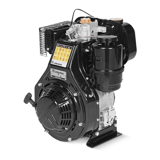
3LD 450
3LD 510
3LD 450/S
3LD 510/S
4LD 640
4LD 705
4LD 820
rd
edition
3
SERVICE
MODEL No.
DATE OF ISSUE
50839
01-94
DATE
A P P R O V A L
02
REVIEW
30.11.2001
1


Need help?
Do you have a question about the 3LD 450 and is the answer not in the manual?
Questions and answers