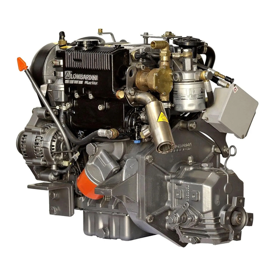
Lombardini LDW 502 Workshop Manual
Hide thumbs
Also See for LDW 502:
- Use maintenance and consumer information (156 pages) ,
- Workshop manual (106 pages) ,
- Service manual (98 pages)
Table of Contents
Advertisement
Quick Links
Advertisement
Table of Contents

Related Manuals for Lombardini LDW 502


Summary of Contents for Lombardini LDW 502
- Page 1 WORKSHOP MANUAL Focs series engines, code 1-5302-351 LDW 502 LDW 602 LDW 903 LDW 1204 LDW 1204/T LDW 702 LDW 1003 LDW 1404 5st Edition SERVICE COMPILER TECO/ATL MODEL N° DATE OF ISSUE DATE REG. CODE ENDORSED REVISION 10.06.99 1-5302-351 50563 04.90...
-
Page 2: General Service Notes
FOREWORD We have done all in our power to give up to date and accurate technical information in this manual. Lombardini engines are, however, constantly developing thus the data in this publication may be liable to modification without prior notice. -
Page 3: Warranty Certificate
WARRANTY CERTIFICATE Engine manufactured by Lombardini S.r.l., are warranted to be free of defects in workmanship or materials for 12 months from the date of delivery to the first purchaser or non more than two (2) years from date of engine delivery to the Original Equipment Manufacturer as defined by Lombardini invoicing, whichever occurs firsts, except as defined below. -
Page 4: Table Of Contents
INDEX This manual contains pertinent information regarding the repair of LOMBARDINI water-cooled, indirect injection Diesel engines type LDW 502-602-903-1204-124/T and LDW 702-1003- 1404: updated November 15, 1999. INDEX TROUBLESHOOTING CHART - LDW FOCS SERIES Pag. SAFETY AND WARNING DECALS - SAFETY INSTRUCTIONS "... - Page 5 ○ ○ ○ ○ ○ ○ ○ ○ ○ ○ ○ ○ ○ ○ ○ Cylinder head tightening procedure- LDW 502, 602, 702, 903 and 1003 ○ ○ ○ ○ ○ ○ ○ ○ ○ ○ ○ ○ ○ ○...
- Page 6 Valve / rocker cover gasket ○ ○ ○ ○ ○ ○ ○ ○ ○ ○ ○ ○ ○ ○ ○ ○ ○ ○ ○ ○ ○ ○ ○ ○ ○ ○ ○ ○ ○ ○ ○ ○ ○ ○ ○ ○...
- Page 7 ○ ○ ○ ○ ○ ○ ○ ○ ○ ○ ○ ○ ○ ○ ○ Engine side wiring harness for the Lombardini supplied control panel ○ ○ ○ ○ ○ ○ ○ ○ ○ ○ ○ ○ ○ ○ ○...
- Page 8 NOTE REG. CODE COMPILER TECO/ATI MODEL N° DATE OF ISSUE DATE ENDORSED REVISION 1-5302-351 50563 04.90 15.11.99...
- Page 9 TROUBLESHOOTING CHART- LDW FOCS SERIES TROUBLESHOOTING CHART- LDW FOCS SERIES SYMPTOM POSSIBLE CAUSE · Low fuel level · · Fuel supply/ return lines clogged · · · · Clogged fuel tank vent · · Fuel pump faulty · · · Fuel entrained with air ·...
-
Page 10: Safety And Warning Decals - Safety Instructions
SAFETY INSTRUCTIONS · Lombardini Engines are built to supply their performances in a safe and long-lasting way. To obtain these results, it is essential for users to comply with the servicing instructions given in the relative manual along with the safety recommendations listed below. - Page 11 · Only check belt tension when the engine is off. · Only use the eyebolts installed by Lombardini to move the engine. These lifting points are not suitable for the entire machine; in this case, the eyebolts installed by the manufacturer should be used.
-
Page 12: I General
Additionally, the maximum engine speed, “K’ number and approval codes are included on the engine data plate. The location of the data plate, as shown below, is identical for all LOMBARDINI LDW-FOCS industrial engines. Please supply the engine data plate information to your Authorized LOMBARDINI Distributor or Dealer when ordering replacement parts or when making technical inquiries. -
Page 13: Diesel Engines
GENERAL POWER RATINGS FOR LDW-FOCS GENSET SPEC DIESEL ENGINES CONTINUOUS (NA) RATING- kW ENGINE 1500 1800 3000 3600 MODEL r/min r/min r/min r/min LDW 602 LDW 903 14.0 14.9 LDW 1204 10.8 18.9 19.9 LDW 1204/T 11.7 14.0 24.8 25.8 LDW 702 10.6 LDW 1003... - Page 14 NOTE: The above cooling system capacities (including radiator) assume that the radiator fitted to your Lombardini FOCS series diesel engine is the standard Lombardini radiator. Different OEM machines may or may not be fitted with a standard Lombardini radiator. Always refer to your equipment documentation for capacity details.
- Page 15 GENERAL LDW 502/602 LDW 903 LDW 1204 LDW 1204/T COMPILER TECO/ATL MODEL N° DATE OF ISSUE DATE ENDORSED REG. CODE REVISION 50563 04.90 15.11.99 1-5302-351...
- Page 16 NOTE: The above cooling system capacities (including radiator) assume that the radiator fitted to your Lombardini FOCS series diesel engine is the standard Lombardini radiator. Different OEM machines may or may not be fitted with a standard Lombardini radiator. Always refer to your equipment documentation for capacity details.
- Page 17 GENERAL LDW 702 LDW 1003 LDW 1404 COMPILER TECO/ATL MODEL N° DATE OF ISSUE DATE ENDORSED REG. CODE REVISION 50563 04.90 15.11.99 1-5302-351...
- Page 18 GENERAL POWER, TORQUE AND SPECIFIC FUEL CONSUMPTION CURVES LDW 502 FOCS, LDW 602 FOCS, LDW 903 FOCS N - 80/1269/CEE- ISO 1585, Gross automotive rating- intermittent operation with variable speed and variable load. NB- ISO 3046/1-IFN - Maximum intermittent rating with no overload capacity; operation with constant speed and variable load.
- Page 19 GENERAL POWER, TORQUE AND SPECIFIC FUEL CONSUMPTION CURVES LDW 1204 FOCS and LDW 1204/T FOCS N - 80/1269/CEE- ISO 1585, Gross automotive rating- intermittent operation with variable speed and variable load. NB- ISO 3046/1-IFN - Maximum intermittent rating with no overload capacity; operation with constant speed and variable load. NA- ISO 3046/1-ICXN- Continuous rating with 10% intermittent overload allowed;...
- Page 20 GENERAL POWER, TORQUE AND SPECIFIC FUEL CONSUMPTION CURVES LDW 702 FOCS, LDW 1003 FOCS, LDW 1404 FOCS N - 80/1269/CEE- ISO 1585, Gross automotive rating- intermittent operation with variable speed and variable load. NB- ISO 3046/1-IFN - Maximum intermittent rating with no overload capacity; operation with constant speed and variable load. NA- ISO 3046/1-ICXN- Continuous rating with 10% intermittent overload allowed;...
- Page 21 GENERAL GENERAL ENGINEERING DRAWINGS- LDW 502 FOCS, LDW 602 FOCS, LDW 903 FOCS COMPILER TECO/ATL MODEL N° DATE OF ISSUE DATE ENDORSED REG. CODE REVISION 50563 04.90 15.11.99 1-5302-351...
- Page 22 GENERAL GENERAL ENGINEERING DRAWINGS- LDW 1204 FOCS, LDW 1204/T FOCS REG. CODE MODEL N° COMPILER TECO/ATI DATE OF ISSUE DATE ENDORSED REVISION 1-5302-351 50563 04.90 15.11.99...
- Page 23 GENERAL GENERAL ENGINEERING DRAWINGS- LDW 702 FOCS, LDW 1003 FOCS, LDW 1404 FOCS COMPILER TECO/ATL MODEL N° DATE OF ISSUE DATE ENDORSED REG. CODE REVISION 50563 04.90 15.11.99 1-5302-351...
-
Page 24: Ldw-Focs Series Maintenance Schedule
After inspection, adjust, repair or replace as required (ž) Clean as often as required Replace air filter after air filter restriction switch indication or one(1) year. Lombardini does not recommend the removal of air filter elements for purposes of inspection. (**) Service oil bath filter element (upper and lower) as required. -
Page 25: Recommended Oil
GENERAL The engine could be damaged if allowed to operate with insufficient oil. It is also dangerous to add too much oil as its combustion could sharply increase the rotation speed. Use a suitable oil in order to protect the engine. The lubrication oil influences the performances and life of the engine in an incredible way. -
Page 26: Diesel Fuel Specifications
Lombardini does not recommend the use of “heating oil”, blended fuel/ waste engine oil, or low grade diesel fuel of any kind. The use of aviation fuels- JP4, JP5 or JP8 must be approved on an application basis and is not recommended for broad range commercial applications. -
Page 27: Anti-Freeze / Coolant Specifications / Details - Focs Series
ANTI-FREEZE / COOLANT SPECIFICATIONS/ DETAILS- FOCS SERIES Ethylene Glycol based Anti-freeze / coolant usage is required for all Lombardini LDW-FOCS series engines. Never operate a LDW-FOCS engine with the cooling system filled with water only. The purpose of the anti-freeze/coolant is three-fold. First the anti-freeze/coolant mixture prevents or reduces the potential for corrosion within the cooling system. -
Page 28: Driving Torques For Standard Screws
GENERAL DRIVING TORQUES FOR STANDARD SCREWS DENOMINATION R ³ ³ ³ ³ ³ 1000 N/mm² R ³ ³ ³ ³ ³ 1200 N/mm² R ³ ³ ³ ³ ³ 800 N/mm² Diameter x pitch (mm) 4x0.70 0.37 0.52 0.62 11.9 5x0.80 0.72 1.01... -
Page 29: Critical Torque Specifications
GENERAL CRITICAL TORQUE SPECIFICATIONS POSITION/ LOCATION Page No. Ref. Diameter/ Pitch TORQUE (mm) (Nm) Injection Pump Control Rod (Rack Adjustment) M3 (special) Injection Pump Control Rod to Unit Injector Rack Bolt M3 (special) Fuel Rail M4x0.7 Connecting Rod (***) M8x1.00 Piston Cooling Jet (LDW 1204/T) M8X1.5 Glow Plugs... -
Page 30: Special Tools
GENERAL SPECIAL TOOLS DESCRIPTION PART No. Fuel delivery equalization tool. Allows the adjustment of individual unit injector fuel 7107-1460-090 delivery. Pre-chamber removal tool. 7107-1460-030 Static timing tool 7107-1460-024 Main bearing cap lateral seal installation tool. 7107-1460-053 Unit injector ring nut tool. 7107-1460-029 Pre-chamber ring nut tool. -
Page 31: Air Restriction Switch
DISASSEMBLY/REASSEMBLY WARNING: Always exercise extreme care when performing engine service work. Refer to and understand the safety guidelines presented on page 3. Additionally, some engine components have sharp edges which could cause cuts if not handled properly. Wear hand protection. Further, some engine components are heavy. As such, wear foot protection to protect from accidental drops of engine components. -
Page 32: Ii Disassembly / Reassembly
DISASSEMBLY/REASSEMBLY AIR FILTER SUPPORT- (INTAKE MANIFOLD) REMOVAL: Disassemble the air filter cover and air filter element. Loosen the crankcase ventilation hose (see page 29) and pull the hose from the air filter support. Remove all bolts that secure the air filter support (1) to the cylinder head. -
Page 33: Cooling Fan Support
DISASSEMBLY/REASSEMBLY FUEL TANK - (OPTIONAL ACCESSORY) A fuel tank may be fitted the the LDW-FOCS engine as shown on an optional basis. Any fuel tank whether engine mounted or not must be maintained. Extreme care must be taken to make sure that only high quality, clean and properly specified fuel is consumed by the LDW- FOCS engine. - Page 34 DISASSEMBLY/REASSEMBLY No. 2 PTO (CRANKSHAFT PULLEY) with “RINGFEDER”- LDW 1204, LDW 1204/T, LDW 1404 The maximum allowable power to be taken from the LDW 1204 and LDW 1204/T and LDW 1404 standard No. 2 PTO is 75% of the speed specific output (see page 10). In order provide 100% of the available power, a “RINGFEDER”...
-
Page 35: Timing Belt Removal
DISASSEMBLY/REASSEMBLY TIMING BELT REMOVAL REMOVAL: Loosen nut (1). Slide the timing belt off of the pulleys. NOTE 1.: Timing belt refitting can be greatly simplified if the engine is rotated until the timing marks align prior to removing the timing belt. -
Page 36: Timing Pulley - Reference Marks
TIMING PULLEY - REFERENCE MARKS All LDW-FOCS engines (502, 602, 903, 1204 and 1204/T) utilize the same camshaft timing pulley. The cam timing of the LDW 502 however, differs from the other LDW-FOCS engines. Carefully review the diagram to the left and the chart below to assure the correct timing marks are used with respect to the engine model. - Page 37 = BDC (Bottom Dead Center) = Intake Valve Opening Angle = Intake Valve Closing Angle = Exhaust Valve Opening Angle = Exhaust Valve Closing Angle LDW 502, 602, 903 and 1204: = 16° BTDC = 36° ABDC = 36° BBDC = 16° ATDC LDW 1204/ T = 10°...
- Page 38 DISASSEMBLY/REASSEMBLY SPEED GOVERNOR The FOCS speed governor is driven by the camshaft and is housed within the cylinder head. Access to the speed governor is gained by removing the camshaft front support as shown. Disassemble the front camshaft support by first loosening and removing three(3) securing bolts holding the camshaft support to the cylinder head, then pulling the support from the cylinder head.
- Page 39 OIL PUMP ASSEMBLY The FOCS oil pump is supplied as an assembly. Lombardini therefore recommends that the oil pump be handled as an assembly from a service standpoint. Lombardini does not recommend that the oil pump be disassembled, then reassembled for purposes of installation on the engine except during emergency situations.
-
Page 40: Crankcase Breather - Ldw 502
5 Cap/ Cover 10 Valve CRANKCASE BREATHER - LDW 502 The crankcase breather system of the LDW 502 is not integral with the valve/ rocker cover as described above. The LDW 502 breather system includes a breather assembly(1), which includes a vapor separation, condensate drain and vacuum regulator. - Page 41 DISASSEMBLY/REASSEMBLY VALVE ADJUSTMENT Valve adjustments should be performed on a cold engine. Remove the engine valve / rocker cover. Rotate the engine to TDC- compression stroke before adjusting the valves on each respective cylinder. Loosen the adjustment lock nut and adjust the clearance at (A) to 0.20mm or 0.15mm at (B) for both intake and exhaust valves.
- Page 42 DISASSEMBLY/REASSEMBLY UNIT INJECTOR REMOVAL / INSTALLATION Unit injectors may require removal for either service on the unit injector, or for purposes of allowing other service operations. If unit injector service is required, a static timing and fuel delivery equalization procedure will be required (see FUEL SYSTEM). If unit injector service is not required, the following procedure may be used to allow unit injector removal and replacement without the need for other adjustments.
-
Page 43: Camshaft Journal / Support Bore Specifications
DISASSEMBLY/REASSEMBLY CAMSHAFT REMOVAL/ REPLACEMENT PREPARATION: Remove the rocker arm assembly, remove the camshaft end cover(1), remove the camshaft timing pulley, remove the governor assembly, remove the fuel lift pump, remove the fuel lift pump push rod. REMOVAL: Gently and slowly, slide the camshaft toward the flywheel end of the engine. -
Page 44: Camshaft Lobe Specifications
CAMSHAFT LOBE SPECIFICATIONS NOTE: The camshaft shown in the figure is reflective of a LDW 903. However, the cam lobes are identical for the LDW 502, LDW 602, LDW 903 and LDW 1204 diesel engines. The cam lobes are slightly different for the LDW 1204/T as is shown in the data below. - Page 45 INSTALLATION VALVE/VALVE GUIDE SPECIFICATIONS Lombardini does not provide installation tools for valve guides. Lombardini recommends that valve guide replacement be done by a suitable shop specializing in cylinder head work. Whether newly installed or existing, the valve guides should conform to the following: 39.5/40.0mm...
- Page 46 Glow Plug Pre-combustion Chamber Ring Nut Cylinder Head NOTE: Pre-combustion chambers are identical for the LDW 602, LDW 903, LDW 1204 and LDW 1204/T. The LDW 502 has a slightly different design than the other FOCS models. REG. CODE COMPILER TECO/ATI MODEL N°...
- Page 47 NORMALLY REQUIRE REMOVAL OR SERVICE AND SHOULD NOT BE DISTURBED UNLESS ABSOLUTELY NECESSARY. DO NOT REMOVE PRE-COMBUSTION CHAMBERS AS PART OF A NORMAL REBUILD OR VALVE JOB. FURTHER, LOMBARDINI RECOMMENDS THAT NEW PRE-COMBUSTION CHAMBERS BE INSTALLED IF REMOVAL OF THE EXISTING PRE-CHAMBERS IS REQUIRED.
- Page 48 IMBALANCE GENUINE LOMBARDINI MARKINGS As part of the high quality standards of Lombardini, pistons are fitted within FOCS engines as a function of finished cylinder size. Four(3) piston classes exist- A,B,C. The piston class is stamped into the bottom of the piston as shown in the diagram (at arrow).
- Page 49 A depending on the cylinder diameters found. NOTE 2: The LDW 502 aluminum version is designed with an aluminum crankcase and non-replaceable cast iron cylinders. The cylinders may be machined 0.500 and 1.000mm identically to standard crankcase versions of the LDW-FOCS.
- Page 50 (with bearings) and torque connecting rod. Replace the connecting rod and/or connecting rod bearings if dimension conformance to the following is not shown. Dim. SPECIFICATION NOTES 126.48÷126.520mm LDW 502=106.98 / 107.02mm 18.015÷18.025mm LDW 1204/T= 20.015 / 20.025 40.021÷40.050mm (Cap Torqued to 40 Nm) 17.996÷18.000mm...
-
Page 51: Connecting Rod Alignment
DISASSEMBLY/REASSEMBLY CONNECTING ROD ALIGNMENT Check the alignment of the connecting rod wrist pin bore with respect to the connecting rod journal diameter by fitting the connecting rod to a suitable fixture as shown or by placing the connecting rod on a mandrel in V-blocks as shown. If the V-block and dial indicator method is used, center the wrist pin in the connecting rod wrist pin bore so that an equal amount of the wrist pin protrudes from each side of the connecting rod. -
Page 52: Connecting Bearing / Rod Cap Installation
DISASSEMBLY/REASSEMBLY CONNECTING BEARING / ROD CAP INSTALLATION Install the connecting rod bearing inserts into the connecting rod and connecting rod cap. Make sure that the back of the bearing insert and the connecting rod and connecting rod cap bore is free of dirt, rust, oil etc. - Page 53 CYLINDER HEAD TIGHTENING PROCEDURE- LDW 502, 602, 702, 903 and 1003: FIGURE A = LDW 502, LDW 602, LDW 702 FIGURE B = LDW 903, LDW 1003 STEP 1: Torque the head bolts to 50 Nm in 10 Nm steps in the order shown.
- Page 54 DISASSEMBLY/REASSEMBLY MAIN BEARING CAPS / BEARINGS- CENTER The center main caps are referenced on the actual cap and on the crankcase as shown to allow replacement of the caps in the identical position of removal. The reference number locations are shown in the figure at the left.
-
Page 55: Crankshaft End Play
DISASSEMBLY/REASSEMBLY THRUST BEARINGS Thrust bearings on the FOCS engine are supported by the rear main bearing cap and the crankcase. The thrust bearing assembly consists of four(4) separate thrust bearing segments. Two(2) of the segments are supported by the crankcase and the remaining two(2) are supported by the rear main bearing cap. -
Page 56: Crankshaft Journal Inspection / Measurement
2mm using a suitable mandrel. CRANKSHAFT LUBRICATION DRILLINGS- TYPICAL The lubrication drillings for the LDW 502(A) and LDW 602-702(B) are shown in the diagram. The lubrication drillings for the LDW 903, LDW 1204 and LDW 1204T are very similar to the LDW 602-702. -
Page 57: Crankshaft Journal Specifications
DISASSEMBLY/REASSEMBLY CRANKSHAFT JOURNAL SPECIFICATIONS For LDW 502,602,903,1204,1204/T A = Main Journals= 47.984 / 48.000mm (WEAR Limit = 47.900mm) For LDW 702,1003,1404 A = Main Journals= 50,981 / 51.000mm (WEAR Limit = 50.900mm) For LDW 502,602,702,903,1003,1204,1204/T,1404 B = Rod Journals = 39.984 / 40.000mm (WEAR Limit = 39.900mm) - Page 58 TURBOCHARGER TURBOCHARGER IDENTIFICATION Only the LDW 1204/T is supplied with a turbocharger. The LDW 1204/T is available in two(2) versions with respect to no-load speed. A version operating up to 3000 rpm and a version operating up to 3600 rpm is offered. The two(2) engine versions are fitted with different turbocharger models with respect to the engine speed.
- Page 59 TURBOCHARGER TURBOCHARGER WASTE GATE ADJUSTMENT- BENCH METHOD The adjustment of the turbocharger wastegate is a critical adjustment that should be carried out with the utmost care. Prepare the following group of tools/ materials. Calibrated, liquid filled pressure gauge with a mid-range scale of 1.2 bar.
- Page 60 LUBRICATION SYSTEM The engine can be damaged if allowed to operate with insufficient oil. It is also dangerous to add too much oil because its combustion may lead to a sharp increase in the rotation speed. Use suitable oil in order to protect the engine. Nothing more than lubrication oil can influence the performances and life of an engine.
- Page 61 OIL PUMP SPECIFICATION: Oil pump delivery (average figures) at 1000 r/min and oil temperature of 120°C ENGINE MODEL DELIVERY (I/min) Pressure (Bar) LDW 502,602,702,903,1003 4.0-4.3 3.0-3.5 LDW 1204,1204/T,1404 6.0-6.5 3.0-4.5 Oil pump delivery (average figures) at 3600 r/min and oil temperature of 120°C...
- Page 62 Total filter area (502,602,903): 730 cm² Total filter area (1204): 1450 cm² NOTE: Always use genuine Lombardini replacement oil filters. Apply a coating of clean engine oil to the oil filter gasket before installation. Hand tighten the oil filter onto the engine.
- Page 63 COOLING SYSTEM The cooling circuit contains fluid under pressure. Do not carry out any inspections until the engine has cooled and even then, open the plug of the radiator or expansion chamber with caution. Keep well away from a hot engine if an electric fan is installed since this could start up even when the engine is at a standstill.
-
Page 64: Cooling System
Tighten, repair or replace as required. NOTE: Lombardini recommends a radiator cap pressure relief setting of 0.7 bar. Do not operate the engine with a pressure cap of higher or lower setting installed. - Page 65 FUEL SYSTEM FUEL SYSTEM SCHEMATIC Fuel Tank Fuel Filter Supply Hose Fuel Pump Injector Injection Pump Fuel Rail Grommet Return Hose Fuel Tank Fill Cap (Vented) 10 Fuel Shut-off Valve (Electric) FUEL FILTER ASSEMBLY Air Bleed Plug Filter Head(Base) Spin-on Fuel Filter Gasket Filter Media Fuel Filter Specifications:...
-
Page 66: Fuel System
FUEL SYSTEM LOMBARDINI CONTINUALLY DEVELOPS THE FOCS DIESEL LINE. CONSTANT RESEARCH AND DEVELOPMENT IS CARRIED OUT TO IMPROVE OVERALL PERFORMANCE OF FOCS PRODUCTS. AS SUCH, THE DESIGN OF THE FOCS UNIT INJECTOR HAS CHANGED DURING THE DEVELOPMENT PROCESS. THE FIGURE ABOVE PROVIDES A REFERENCE FOR THE THREE(3) DIFFERENT VERSIONS OF THE FOCS UNIT INJECTOR TO DATE. - Page 67 FUEL SYSTEM FUEL SYSTEM SPECIAL TOOLS UNION- 1460.028 FUNCTION: Allows high pressure testing of unit injectors. Use for both static timing and pressure testing of early unit injectors. The 1460.028 union screws directly into the unit injector after removal of the high pressure plug.
- Page 68 FUEL SYSTEM UNIT INJECTOR: The unit injectors fitted within Lombardini FOCS diesel engines are designed by Lombardini. One unit injector is required for each cylinder. In the continuing development of the FOCS diesel engine, design changes have been made to the unit Injector resulting in less that total interchangability between older and newer FOCS engines.
- Page 69 FUEL SYSTEM UNIT INJECTOR REASSEMBLY (CONT.) With reference to the previous frame, and the exploded view of the unit injector on the previous page, continue to introduce the plunger into the unit injector, while gently rotating rack lever (8) back and forth until index (M) can be engaged with the rack lever (8).
- Page 70 FUEL SYSTEM WARNING: THE TESTING AND SERVICE OF FUEL INJECTION EQUIPMENT SUCH AS DETAILED BELOW INCLUDES HIGH PRESSURE AND SPRAYING FLUIDS. WEAR PROPER EYE AND HAND PROTECTION. DO NOT ALLOW ANY PART OF YOUR BODY TO COME INTO CONTACT WITH HIGH PRESSURE FUEL OR TESTING FLUID. FURTHER, HIGH PRESSURE FUEL IS VERY FLAMMABLE.
- Page 71 Alternately rotate the engine back and forth until fuel is injected out LDW 602, 903, LDW 702 LDW 502 of the injection timing tool and free of air. 1204,1204/T 1003,1404 (mm) Rotate the engine in opposite normal direction approximately 90°.
- Page 72 TDC with respect to the findings of the timing fixture assembly- 1460-048. Lombardini strongly recommends the use of the 1460-048 timing fixture for purposes of static timing adjustments.
-
Page 73: Unit Injector Delivery Equalization
FUEL SYSTEM UNIT INJECTOR DELIVERY EQUALIZATION- PREPARATION Due to the fact that unit injectors are both injection pump and injector, all unit injectors within a FOCS diesel engine must be equalized to facilitate the identical delivery of fuel within individual cylinders. The equalization procedure is a operational test with the valve cover removed. - Page 74 (battery chargers, load testers, meters, etc.). BATTERY SIZING: The chart presented below provides strict guidelines for the sizing of system batteries for Lombardini FOCS diesel engines. Batteries must be sized so as to provide sufficient reserve capacity (Amp-Hours), but yet not so large as to damage the starter motor due to excessive amperage.
- Page 75 ELECTRICAL SYSTEM ISKRA ALTERNATOR- 14V / 33A NOMINAL VOLTAGE: NOMINAL CURRENT OUTPUT: MAXIMUM r/min: 12000 r/min VOLTAGE REGULATOR: AER 1503 ROTATION (VIEWED AT PULLEY END): CLOCKWISE NOTE: Pulley nut torque (1): 35-45 Nm ISKRA 14V / 33A PERFORMANCE CURVE The attached performance curve was plotted at a constant system voltage voltage of 13V and at an ambient temperature of 25°C.
- Page 76 ELECTRICAL SYSTEM MARELLI ALTERNATOR (AA 125 R) - 14V / 45A NOMINAL VOLTAGE: NOMINAL CURRENT OUTPUT: MAXIMUM r/min: 14000 r/min VOLTAGE REGULATOR: RTT 119 A BEARING (Pulley End): 6203-2Z BEARING (Voltage Regulator End) 6201-2Z/C3 ROTATION (VIEWED AT PULLEY END): CLOCKWISE NOTE:1.
- Page 77 ELECTRICAL SYSTEM 12V ELECTRICAL SCHEMATIC- MARELLI 14V-33A Alternator Starter Motor Battery- (See below for sizing details) Glow Plugs Thermistor (Glow Plug Controller Circuit) Glow Plug Controller / Timer Key Switch System Fuse, 30A (502, 602), 50A (903), 80A (1204, 1204/T) Fuse (Accessory)- 5A 10 Fuel Valve 11 Glow Plug Indicator Lamp...
- Page 78 ELECTRICAL SYSTEM PERFORMANCE CURVE- 20A FLYWHEEL ALTERNATOR The performance curve at the left was plotted at a constant system voltage of 12V and an ambient temperature of 20°C. RPM values shown on the performance curve are engine speeds. The statistical charging output of the flywheel alternator is +10% to - 5% of the values shown.
- Page 79 ELECTRICAL SYSTEM 12V ELECTRICAL SCHEMATIC- 20/30A FLYWHEEL ALTERNATOR Alternator Starter Motor Battery- (See below for sizing details) Glow Plugs Thermistor (Glow Plug Controller Circuit) Glow Plug Controller / Timer Key Switch System Fuse, 30A (502, 602), 50A (903,702,1003), 80A (1204, 1204/T, 1404) Fuse (Accessory)- 5A 10 Fuel Valve...
- Page 80 The diagram below provides details of the control panel. Please also refer to the diagram on page 70, which details the interface engine side wiring harness for the Lombardini control panel. The panel connector index numbers correspond to the index numbers for the engine side harness.
- Page 81 ELECTRICAL SYSTEM ENGINE SIDE WIRING HARNESS FOR THE LOMBARDINI SUPPLIED CONTROL PANEL In conjuction with the engine control panel detailed on page 69, LDW-FOCS engines may be fitted with an engine side wiring harness and optional sensors. The following diagram details the engine side wiring harness. Please also reference the diagram on page 69. The connector index numbers as shown on the engine side wiring harness interfaces with the connector index numbers for the control panel.
- Page 82 ELECTRICAL SYSTEM BOSCH 12V / 1.1 KW STARTER MOTOR (DW 12V) NOTE: Before removing the starter motor or attempting to service any electrical component, remove the negative(-) cable from the system battery. Distance (A), from starter mounting flange to ring gear face must be checked and confirmed to be 17.5 / 19.5mm.
-
Page 83: Electrical System
All FOCS diesel engines should be preheated before attempting to start the engine. Further, Lombardini recommends that all applications be fitted with an automatic glow plug controller system such as is detailed below. The use of a glow plug control circuit will insure the proper amount of preheat at all temperatures. -
Page 84: Idle Speed Adjustment
Some fine adjustment may be required after the engine is applied within the given machine. TORQUE DEVICE ADJUSTMENT (WITHOUT DYNAMOMETER) Lombardini recommends that the engine torque device be adjusted on a dynamometer. Therefore, the adjustment procedure presented in the following is only approximate. WARNING: ADJUSTMENT OF THE TORQUE DEVICE WILL REQUIRE THE USE OF TOOLS IN CLOSE PROXIMITY TO THE COOLING FAN. - Page 85 8. Allow the engine to cool at idle speed for 10 minutes. DYNO TEST PARAMETERS- kW and SPECIFIC FUEL CONSUMPTION ENGINE r/min NB Output (kW) Specific Fuel Consumption Sec./100cc g/kW*hr LDW 502 2200 285-299 3600 115-120 326-340 LDW 602 2200...
- Page 86 STORAGE STORAGE Measures shouLd be taken to protect your FOCS series engine if the engine is not operated for a period of 30 days or more. Proper storage will protect the engine from corrosion and prevent costly repairs due to storage induced problems. STORAGE - 1 to 6 MONTHS 1.
- Page 87 NOTE COMPILER TECO/ATL MODEL N° DATE OF ISSUE DATE ENDORSED REG. CODE REVISION 50563 04.90 15.11.99 1-5302-351...
- Page 88 Cod. fiscale e Partita IVA 01829970357 - CEE Code IT 01829970357 E-MAIL: atl@lombardinifim.it Internet: http://www.lombardinifim.it La Lombardini si riserva il diritto di modificare in qualunque momento i dati contenuti in questa pubblicazione. Lombardini se rèserve le droit de modifier, à n'importe quel moment, les données reportées dans cette publication.
Need help?
Do you have a question about the LDW 502 and is the answer not in the manual?
Questions and answers
Zdravím ,kde se dá sehnat olejové čerpadlo na LDW 702. Děkuji za odpověď