Tennant T20 Service Information Manual
S/n 008000- rider scrubber
Hide thumbs
Also See for T20:
- Service information manual (166 pages) ,
- Operator's manual (118 pages) ,
- Instruction bulletin (4 pages)
Table of Contents
Advertisement
Quick Links
Download this manual
See also:
Operator's Manual
The Safe Scrubbing Alternative
ES
Extended Scrub System
®
Tennant True
Hygenic
Fully Cleanable tanks
®
FloorSmart
Integrated Cleaning system
®
IRIS
a Tennant Technology
®
Pro-Panel™ Controls
Insta-Fit™ Adapter
For the latest Parts Manuals and other
language Operator Manuals, visit:
www.tennantco.com/manuals
®
Parts
®
(S/N 008000-
Service Information Manual
*9016205*
T20
Rider Scrubber
English EN
9016205
Rev. 00 (5-2017)
)
Advertisement
Table of Contents
Troubleshooting

Subscribe to Our Youtube Channel
Related Manuals for Tennant T20


Summary of Contents for Tennant T20
- Page 1 Tennant True Parts ® Hygenic Fully Cleanable tanks ® FloorSmart Integrated Cleaning system ® IRIS a Tennant Technology ® Pro-Panel™ Controls Insta-Fit™ Adapter 9016205 For the latest Parts Manuals and other Rev. 00 (5-2017) language Operator Manuals, visit: *9016205* www.tennantco.com/manuals...
-
Page 2: Introduction
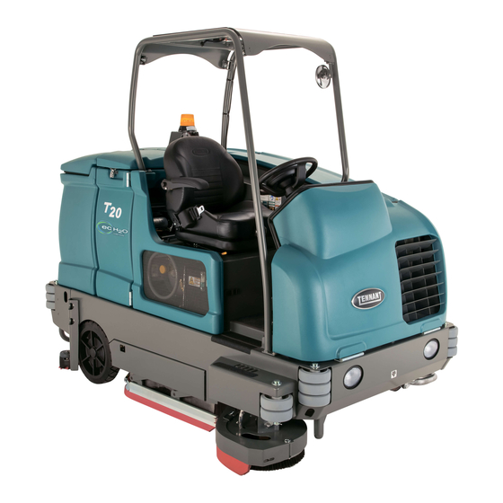
INTRODUCTION INTENDED USE This manual is available for each new model. It provides The T20 is an industrial rider machine designed to scrub hard surfaces (concrete, asphalt, stone, synthetic, necessary operation and maintenance instructions. etc). Typical applications include industrial warehouses,... -
Page 3: Table Of Contents
REPLACING OR ADJUSTING THE SIDE AIR FILTER ..........43 BRUSH SQUEEGEE BLADE FUEL FILTER ...........43 (OPTION) ..........61 FUEL LINES ..........43 LEVELING THE REAR SQUEEGEE ..62 PRIMING THE FUEL SYSTEM ....44 ADJUSTING THE REAR SQUEEGEE BLADE DEFLECTION ......63 SKIRTS AND SEALS ........64 T20 Service Information (5-2017) - Page 4 SQUEEGEE LOWER ........137 LPG ENGINE HARNESS ELECTRICAL SQUEEGEE LIFT........138 SCHEMATIC ...........84 MAIN BRUSH ON (CYLINDRICAL) ....139 T20 OPTION COMPONENTS ......87 MAIN BRUSH ON (DISK) ......140 KEY SWITCH ..........88 SIDE BRUSH ON ........141 MAIN BRUSHES ON ........91 SCRUB VACUUM FAN ON ......142...
- Page 5 MANUAL MODE........159 CONFIGURATION MODE .....160 SELF TEST MODE ........161 INPUT DISPLAY MODE ......163 THROTTLE ADJUST MODE ....164 DOWN PRESSURE ADJUST MODE ..165 MEMBRANE TEST MODE.....167 FRONT TIRE AND WHEEL SUPPORT ..168 REPLACE FRONT DRIVE WHEEL ..168 T20 Service Information (5-2017)
-
Page 6: Safety Precautions
WARNING: Moving belt and fan. Keep − With pads or accessories not supplied away. or approved by Tennant. The use of other pads may impair safety. WARNING: Engine emits toxic gases. − In areas where flammable Serious injury or death can result. - Page 7 − Do not modify the machine from its − Always be aware of surroundings original design. while operating machine. − Use Tennant supplied or approved − Do not access the video / help screens replacement parts. while the machine is moving.
- Page 8 Apply parking brake before leaving machine. Located on frame of machine. Located next to the ignition switch on the instrument panel. (LPG machines only) T20 Service Information (5-2017) T20 Gas/LPG 9016200 (08−2016)
- Page 9 Located on the side of the bumper, on the exhaust shield, on the hydraulic reservoir, and Located on engine on the scrub head (disk head machines only). compartment panel. T20 Gas/LPG 9016200 (08−2016) Home Find... Go To.. T20 Service Information (5-2017)
-
Page 10: General Information
GENERAL INFORMATION GENERAL INFORMATION ELECTRICAL COMPONENT LOCATOR T20 Electrical Component Locator Page 1 of 10 VALVE SOL‐7 T20 Service Information (5-2017) - Page 11 GENERAL INFORMATION T20 Electrical Component Locator Page 2 of 10 IGNITION SWITCH S‐1 SPRAY NOZZLE SWITCH S‐25 LIGHT SWITCH S‐4 ACCESS PANEL FOR RIGHT SIDE of ENGINE ACCESS PANEL REMOVED HORN SWITCH S‐22 T20 Service Information (5-2017)
- Page 12 GENERAL INFORMATION T20 Electrical Component Locator Page 3 of 10 T20 Service Information (5-2017)
- Page 13 GENERAL INFORMATION T20 Electrical Component Locator Page 4 of 10 T20 Service Information (5-2017)
- Page 14 GENERAL INFORMATION T20 Electrical Component Locator Page 5 of 10 GAS/LPG ENGINE GAS/DIESEL FUEL LEVEL SENDER S-7 DIAGNOSTIC CONNECTOR HYDRAULIC FILTER CLOGGED SWITCH S-17 FRONT TOP VIEW FRONT HYDRAULIC OIL TEMPERATURE FaST COMPONENTS SENSOR S-20 (BACK SIDE) T20 Service Information (5-2017)
- Page 15 GENERAL INFORMATION T20 Electrical Component Locator Page 6 of 10 AUTO FILL SOLENOID VALVES INNER VIEW SOL-2 SOL-1 ES PUMP RECOVERY TANK HALF FULL SWITCH S-16 OUTSIDE TANK TOP VIEW INSIDE TANK SPRAY NOZZLE/WAND PUMP RECOVERY TANK FULL SWITCH S-15...
- Page 16 GENERAL INFORMATION T20 Electrical Component Locator Page 7 of 10 Diesel Engine Coolant Crankshaft Temperature Position Sensor Sensor Pressure Switch T20 Service Information (5-2017)
- Page 17 GENERAL INFORMATION T20 Electrical Component Locator Page 9 of 10 GAS/LPG T20 Service Information (5-2017)
- Page 18 GENERAL INFORMATION T20 Electrical Component Locator Page 10 of 10 GAS/LPG T20 Service Information (5-2017)
-
Page 19: Hydraulic Component Locator
GENERAL INFORMATION HYDRAULIC COMPONENT LOCATOR T20 Hydraulic Component Locator Page 1 of 8 VACUUM FAN MOTOR SIDE BRUSH MOTOR CYLINDRICAL MAIN BRUSH MOTOR (REAR) FRONT PROPEL MOTOR LEFT SIDE SQUEEGEE LIFT CYLINDER T20 Service Information (5-2017) - Page 20 GENERAL INFORMATION T20 Hydraulic Component Locator Page 2 of 8 SIDE BRUSH MOTOR VACUUM FAN MOTOR PROPEL MOTOR DISK MAIN BRUSH MOTORS LEFT SIDE SQUEEGEE LIFT CYLINDER T20 Service Information (5-2017)
- Page 21 GENERAL INFORMATION T20 Hydraulic Component Locator Page 3 of 8 HYDRAULIC OIL RESERVOIR HYDRAULIC OIL FILTER STEERING VALVE FRONT CYLINDRICAL MAIN BRUSH RIGHT SIDE SQUEEGEE LIFT CYLINDER MOTOR (FRONT) T20 Service Information (5-2017)
- Page 22 GENERAL INFORMATION T20 Hydraulic Component Locator Page 4 of 8 See pages 16 and 17 for more SCRUB MANIFOLD information on the Scrub and HYDRAULIC OIL HEAT SV1, SV2, SV3, SV4,SV6, SV7 Side Brush manifolds RV1, RV2, CV1, PC1, PC2...
- Page 23 GENERAL INFORMATION T20 Hydraulic Component Locator Page 5 of 8 MAIN SQUEEGEE LIFT CYLINDER STEERING CYLINDER FRONT BUMPER (INNER VIEW) SIDE BRUSH EXTEND CYLINDER SIDE BRUSH LIFT CYLINDER T20 Service Information (5-2017)
- Page 24 GENERAL INFORMATION T20 Hydraulic Component Locator Page 6 of 8 DISK SCRUB HEAD LIFT CYLINDER CYLINDRICAL SCRUB HEAD LIFT CYLINDER T20 Service Information (5-2017)
- Page 25 GENERAL INFORMATION T20 Hydraulic Component Locator Page 7 of 8 SCRUB MANIFOLD DETAILS T20 Service Information (5-2017)
- Page 26 GENERAL INFORMATION T20 Hydraulic Component Locator Page 8 of 8 SIDE BRUSH MANIFOLD DETAILS FRONT SV10 SV11 SV12 P4 & OR3 0.040 in (1.02 mm) orifice T20 Service Information (5-2017)
-
Page 27: Specifications
GENERAL INFORMATION SPECIFICATIONS T20 Specifications Page 1 of 4 T20 Service Information (5-2017) - Page 28 GENERAL INFORMATION T20 Specifications Page 2 of 4 T20 Service Information (5-2017)
- Page 29 GENERAL INFORMATION T20 Specifications Page 3 of 4 T20 Service Information (5-2017)
- Page 30 GENERAL INFORMATION T20 Specifications Page 4 of 4 T20 Service Information (5-2017)
-
Page 31: Maintenance
MAINTENANCE MAINTENANCE MAINTENANCE MAINTENANCE T20 Service Information (5-2017) -
Page 32: Maintenance Chart
HYDO . TennantTrue premium hydraulic fluid or equivalent WG . . . Water and ethylene glycol anti-freeze, −34<?> C (−30<?> F) SPL . . . Special lubricant, Lubriplate EMB grease (Tennant part number 01433−1) NOTE: More frequent maintenance intervals may be required in extremely dusty conditions. - Page 33 HYDO . TennantTrue premium hydraulic fluid or equivalent WG . . . Water and ethylene glycol anti-freeze, −34<?> C (−30<?> F) SPL . . . Special lubricant, Lubriplate EMB grease (Tennant part number 01433−1) NOTE: More frequent maintenance intervals may be required in extremely dusty conditions.
- Page 34 HYDO . TennantTrue premium hydraulic fluid or equivalent WG . . . Water and ethylene glycol anti-freeze, −34<?> C (−30<?> F) SPL . . . Special lubricant, Lubriplate EMB grease (Tennant part number 01433−1) NOTE: More frequent maintenance intervals may be required in extremely dusty conditions.
-
Page 35: Yellow Touch Points
DO NOT fill past the top indicator mark. The engine oil capacity for Mitsubishi engines is 4.7 L (5 qt) with oil filter. The engine oil capacity for diesel engines is 6L (6.35 qt) with oil filter. T20 Service Information (5-2017) -
Page 36: Rear Wheel Bearings
Lubricate the three torque tube fittings after every and repack and adjust every 400 hours of 200 hours of operation. The first two fittings are operation. Use Lubriplate EMB grease (Tennant located on each side of the machine and the third part number 01433 1). -
Page 37: Hydraulics
Drain and refill the hydraulic fluid reservoir with new TennantTrue premium hydraulic fluid after every 2400 hours of operation. WARNING: Burn hazard. Hot surface. Do NOT touch. Replace the hydraulic strainer outlet after every 2400 hours of operation. T20 Service Information (5-2017) -
Page 38: Hydraulic Fluid
Serious infection or reaction can occur if proper medical treatment is If using a locally-available hydraulic fluid, be sure the specifications match Tennant hydraulic fluid not given immediately. specifications. Substitute fluids can cause Contact a mechanic or supervisor if a leak is premature failure of hydraulic components. -
Page 39: Engine - Gas/Lpg
Flush the radiator and the cooling system after every 800 hours of operation. The cooling system must be completely filled with coolant to keep the engine from overheating. T20 Service Information (5-2017) -
Page 40: Air Filter
FOR SAFETY: When servicing machine, keep flames and sparks away from fuel system FOR SAFETY: When servicing machine, keep service area. Keep area well ventilated. flames and sparks away from fuel system service area. Keep area well ventilated. T20 Service Information (5-2017) -
Page 41: Engine Belt
Inspect the PCV system after every 100 hours of from the battery or add water to the battery. operation. FOR SAFETY: When servicing machine, avoid contact with battery acid. SPARK PLUGS MITSUBISHI ENGINES Replace the spark plugs after every 1000 hours of operation. T20 Service Information (5-2017) -
Page 42: Engine - Diesel
800 hours of operation. The cooling system must be completely filled with coolant to keep the engine from overheating. When filling the cooling system, open the drain cock to bleed the air from the system. T20 Service Information (5-2017) T20 Diesel 9016250 (08−2016) -
Page 43: Air Filter
FUEL SYSTEM. When the fuel lines are not installed, plug both ends with clean cloth or paper to prevent dirt from entering the lines. Dirt in the lines can cause fuel injection pump malfunction. T20 Service Information (5-2017) T20 Diesel 9016250 (08−2016) -
Page 44: Priming The Fuel System
13 mm (0.50 in) from a force of 4 to 5 kg (8 to 10 lb) applied at the mid-point of the longest span. FOR SAFETY: When servicing machine, avoid contact with battery acid. WARNING: Moving belt and fan. Keep away. T20 Service Information (5-2017) T20 Diesel 9016250 (08−2016) -
Page 45: Fuses And Relays
Not Used 12 VDC, 40 A Not Used 12 VDC. 40 A Not Used 12 VDC. 40 A FaST Water Pump (located in FaST harness) 12 VDC. 40 A Spray Wand (located in Spray T20 Service Information (5-2017) wand harness) -
Page 46: Engine Harness Fuses And Relays
Once a circuit Otherwise one brush or pad will be more breaker is tripped, allow breaker to cool and then aggressive than the other. press the reset button to manually reset the breaker. T20 Service Information (5-2017) -
Page 47: Replacing Disk Brushes Or Pad Driver
8. Place the new brushes underneath the scrub head and lift each brush up onto the hub until the brush locks onto the hub. 9. Rotate the disk brush head back to the scrub position until the head locks into place. T20 Service Information (5-2017) -
Page 48: Checking The Disk Scrub Head Stop Bumpers
Replace worn or damaged pad on the pad driver. Then reinstall the bumpers. center disk to secure the pad in place on the pad driver. 4. Reinsert the pad driver into the machine. T20 Service Information (5-2017) -
Page 49: Cylindrical Brushes
1. Raise the scrub head. FOR SAFETY: Before leaving or servicing machine, stop on level surface, set parking brake, turn off machine, and remove key. 5. Pull the brushes out from the scrub head. 2. Open the outer brush doors. T20 Service Information (5-2017) -
Page 50: Checking Cylindrical Brush Pattern
10. Check the brush pattern and adjust if needed after rotating them. Refer to CHECKING AND ADJUSTING THE MAIN BRUSH PATTERN. 11. Check the brush pattern and adjust if needed after rotating them. Refer to CHECKING CYLINDRICAL BRUSH PATTERN. T20 Service Information (5-2017) -
Page 51: Adjusting The Cylindrical Brush Taper
Always adjust the nut on each drag link an equal number of turns. NOTE: Two full turns of the drag link adjustment bolt will change the brush pattern approximately 25 mm (1 in). 2. Recheck the pattern. Readjust if necessary. T20 Service Information (5-2017) -
Page 52: Side Brush (Option)
3. Squeeze the spring handles and let the side brush drop to the floor. T20 Service Information (5-2017) -
Page 53: Fast System
6. Connect the FaST supply hose to the carton out from the compartment and discard. FaST PAK hose connector. Scrub with the FaST system for a few minutes to allow the detergent to reach maximum foaming. T20 Service Information (5-2017) -
Page 54: Cleaning The Fast Supply Hose Connector
The FaST system filter screen filters water from the solution tank as the water flows into the FaST system. Remove the filter screen bowl and clean the filter screen after every 50 hours of operation. Empty the solution tank before removing the filter. T20 Service Information (5-2017) -
Page 55: Ec H2O Module Flush Procedure
NOTE: The module will automatically shut off ec H2O system outlet hose. when the flush cycle is complete (approx. 7 minutes). The module must run the full 7 minute cycle in order to reset the system indicator light and alarm. T20 Service Information (5-2017) -
Page 56: Cleaning The Ec H2O Filter Screen
NOTE: The outlet and intake hoses must be down between the ec H2O assembly and the bracket so they are not pinched or damaged when the operator seat cover is closed. 12. Close the operator seat cover. T20 Service Information (5-2017) -
Page 57: Squeegee Blades
7. Remove the rear squeegee. 3. Remove both mounting knobs from the rear squeegee assembly. 4. Turn on the machine, raise the scrub head, and turn off the machine. 5. Remove the rear squeegee assembly from the machine. T20 Service Information (5-2017) - Page 58 13. Install the new front squeegee blade or rotate the existing blade to the new edge. Be sure the holes in the squeegee blade are hooked 10. Tighten the rear retaining band tension latch. onto the tabs. T20 Service Information (5-2017)
-
Page 59: Replacing Or Rotating The Side Squeegee Blades
17. Check and adjust the rear squeegee if necessary. Refer to ADJUSTING THE REAR SQUEEGEE BLADE DEFLECTION and LEVELING THE REAR SQUEEGEE sections of this manual. 4. Remove the retaining band from the side squeegee assembly. T20 Service Information (5-2017) - Page 60 Discard the squeegee blade if both edges are worn. 9. Close the outer brush door. 6. Install the new or rotated squeegee blades. 7. Reattach the side squeegee retaining band to the side squeegee assembly. T20 Service Information (5-2017)
-
Page 61: Replacing Or Adjusting The Side Brush Squeegee Blade (Option)
3. Open the retaining band tension latch. 6. Reinstall the retaining band tension latch. 7. Reinstall the squeegee bumper and reinsert the pins. T20 Service Information (5-2017) -
Page 62: Leveling The Rear Squeegee
5. Drive the machine forward with the squeegee down to recheck the squeegee blade deflection if adjustments were made. 6. Readjust the squeegee blade deflection if necessary. T20 Service Information (5-2017) -
Page 63: Adjusting The Rear Squeegee Blade Deflection
The correct amount of deflection is 12 mm (0.50 in) for scrubbing 5. Readjust the squeegee blade deflection if smooth floors and 15 mm (0.62 in) for rough necessary. floors. 12 mm (0.50 in) T20 Service Information (5-2017) -
Page 64: Skirts And Seals
The skirts should be between 0 to 6 mm (0 to 0.25 in) from the floor when the scrub head is down. RECOVERY TANK SEAL Check the recovery tank cover seal for damage and wear daily. T20 Service Information (5-2017) -
Page 65: Brakes And Tires
FRONT WHEEL Torque the front wheel nuts twice in the pattern shown to 122 to 149 Nm (90 to 110 ft lb) after the first 50 hours of operation, and after every 800 hours there after. T20 Service Information (5-2017) -
Page 66: Pushing, Towing, And Transporting The Machine
AND is 380 mm (15 in) or less from the ground. 4. To winch the machine onto the truck or trailer, attach the winching chains to the holes in the rear jacking brackets behind the rear tires. T20 Service Information (5-2017) - Page 67 FOR SAFETY: When unloading machine off truck or trailer, use winch. Do not drive the machine off the truck or trailer unless the loading surface is horizontal AND 380 mm (15 in) or less from the ground. T20 Service Information (5-2017)
-
Page 68: Machine Jacking
FOR SAFETY: When servicing machine, block machine tires before jacking machine up. Use a hoist or jack that will support the weight of the machine. Jack machine up at designated locations only. Support machine with jack stands. T20 Service Information (5-2017) -
Page 69: Freeze Protection (Machines Without Ec−H2O System)
11. The remaining RV antifreeze does not need to be drained from the solution tank. NOTE: Storing or transporting machines equipped with the ES or the FaST system in freezing temperatures requires special procedures. Consult a TENNANT representative for more information. T20 Service Information (5-2017) - Page 70 12. Insert the intake and outlet hoses down between the ec H2O assembly and the bracket. 13. Return the intake flush hose to the storage bag behind the operator seat. T20 Service Information (5-2017)
-
Page 71: Priming The Ec H2O System
8. Disconnect the outlet flush hose from the ec H2O system outlet hose and return the flush hose to the storage bag. 9. Reconnect the ec H2O system outlet hose to the hose to the scrub head. T20 Service Information (5-2017) -
Page 72: Electrical Troubleshooting
* Call Technical Services if Diagnostic Time Exceeds One Hour With Unknown Cause or Course of Action. NOTE: Troubleshooting charts may be shown with optional equipment. The optional equipment may not be specified in these charts. Some machines may not be equipped with all components shown. T20 Service Information (5-2017) -
Page 73: Schematic Symbols
SV – Solenoid Valve SW – Switch Example of Wiring Numbers & Colors: Wiring Color Codes (Unless otherwise marked) Right Most Digit Color of Wire of WireNumber Pink Brown Orange 1 RED 13 BLK Yellow Green Blue Purple Gray White T20 Service Information (5-2017) -
Page 74: Machine Electrical Schematic
ELECTRICAL TROUBLESHOOTING STANDARD PARTS MACHINE ELECTRICAL SCHEMATIC Fig. 61 − Electrical Schematic 1075421 − 356681 − T20 T20 Gas/LPG 9016201 (12−2016) 2‐124 T20 Service Information (5-2017) Home Find... Go To.. - Page 75 STANDARD PARTS ELECTRICAL TROUBLESHOOTING Fig. 61 − Electrical Schematic MACHINE ELECTRICAL SCHEMATIC (CONTINUED) 1075421 − 356681 − T20 T20 Gas/LPG 9016201 (8−2016) 2‐125 Home Find... Go To.. T20 Service Information (5-2017)
- Page 76 ELECTRICAL TROUBLESHOOTING STANDARD PARTS Fig. 61 − Electrical Schematic MACHINE ELECTRICAL SCHEMATIC (CONTINUED) 1075421 − 356681 − T20 2‐126 T20 Gas/LPG 9016201 (8−2016) T20 Service Information (5-2017) Home Find... Go To..
- Page 77 STANDARD PARTS ELECTRICAL TROUBLESHOOTING Fig. 61 − Electrical Schematic MACHINE ELECTRICAL SCHEMATIC (CONTINUED) 1075421 − 356681 − T20 T20 Gas/LPG 9016201 (8−2016) 2‐127 Home Find... Go To.. T20 Service Information (5-2017)
- Page 78 ELECTRICAL TROUBLESHOOTING STANDARD PARTS Fig. 61 − Electrical Schematic MACHINE ELECTRICAL SCHEMATIC (CONTINUED) 1075421 − 356681 − T20 2‐128 T20 Gas/LPG 9016201 (8−2016) T20 Service Information (5-2017) Home Find... Go To..
- Page 79 STANDARD PARTS ELECTRICAL TROUBLESHOOTING Fig. 61 − Electrical Schematic MACHINE ELECTRICAL SCHEMATIC (CONTINUED) 1075420 − 356680 T20 Gas/LPG 9016201 (8−2016) 2‐129 Home Find... Go To.. T20 Service Information (5-2017)
- Page 80 ELECTRICAL TROUBLESHOOTING NDARD PARTS MACHINE ELECTRICAL SCHEMATIC (CONTINUED) Fig. 61 − Mitsubishi Electrical Schematic 1075421 − 356681 − T20 T20 Gas/LPG 9016201 (8−2016) T20 Service Information (5-2017) Home Find... Go To..
-
Page 81: Diesel Engine Harness Electrical Schematic
ELECTRICAL TROUBLESHOOTING DIESEL ENGINE HARNESS ELECTRICAL SCHEMATIC STANDARD PARTS Fig. 57 − Electrical Schematic 1075420 − 356680 T20 Service Information (5-2017) -
Page 82: Gas Engine Harness Electrical Schematic
ELECTRICAL TROUBLESHOOTING GAS ENGINE HARNESS ELECTRICAL SCHEMATIC (MITSUBISHI) STANDARD PARTS Fig. 62 − Mitsubishi Electrical Schematic, Gas Engine Harness 1071653− 356303 T20 Service Information (5-2017) - Page 83 ELECTRICAL TROUBLESHOOTING STANDARD PARTS GAS ENGINE HARNESS ELECTRICAL SCHEMATIC (MITSUBISHI) (CONTINUED) Fig. 62 − Mitsubishi Electrical Schematic, Gas Engine Harness 1071653− 356303 T20 Gas/LPG 9016201 (8−2016) 2‐133 T20 Service Information (5-2017) Home Find... Go To..
-
Page 84: Lpg Engine Harness Electrical Schematic
ELECTRICAL TROUBLESHOOTING LPG ENGINE HARNESS ELECTRICAL SCHEMATIC (MITSUBISHI) STANDARD PARTS Fig. 63 − Mitsubishi Electrical Schematic, LPG Engine Harness 1071654− 356304 T20 Service Information (5-2017) - Page 85 ELECTRICAL TROUBLESHOOTING STANDARD PARTS LPG ENGINE HARNESS ELECTRICAL SCHEMATIC (MITSUBISHI) (CONTINUED) Fig. 63 − Mitsubishi Electrical Schematic, LPG Engine Harness 1071654− 356304 T20 Service Information (5-2017) T20 Gas/LPG 9016201 (8−2016) 2‐135 Home Find... Go To..
- Page 86 ELECTRICAL TROUBLESHOOTING T20 Service Information (5-2017)
-
Page 87: T20 Option Components
Recovery Tank Half Full Switch S-16 High Flow Valve (SOL-5), FaST Side Brush Valve (SOL-6) Detergent Pump ES Pump Spray Hose Pump Spray Hose Relay Spray Hose Switch S-25 E = Electrical Component H = Hydraulic Component T20 Service Information (5-2017) -
Page 88: Key Switch
Start Start Key Switch Key Switch Run Position Start Position Spring Loaded‐Returns to “RUN” Unless Held SWITCH TERMINAL MARKING GLOW PLUG NO CONNECTIONS START “ . “ Indicates a common connection Common connections in various switch positions should be less than one (1) ohm resistance. T20 Service Information (5-2017) - Page 89 ELECTRICAL TROUBLESHOOTING T20 Key OFF Power Distribution Conditions: Key off 12 VDC 13/BLK 1/RED ALTERNATOR 1/RED GREEN JUMPER WIRE 1/RED Touch Panel / Control Board 13/BLK PIN P2-33 13/BLK PIN P2-34 13/BLK PIN P2-35 KEY SWITCH STATIC GROUND PIN P1-23...
- Page 90 ELECTRICAL TROUBLESHOOTING T20 Key ON Power Distribution Conditions: Key on, engine off 12 VDC 13/BLK 1/RED ALTERNATOR 1/RED GREEN JUMPER WIRE 1/RED ALTERNATOR LAMP FUSE 1 13/BLK 13/BLK 15 AMP KEY SWITCH Touch Panel / TO FUSES Control Board AUX. 1 9 &12...
-
Page 91: Main Brushes On
ELECTRICAL TROUBLESHOOTING T20 Main Brushes ON Conditions: Key on, engine running, scrubbing or sweeping system on, propel forward or reverse Maximum Amp. Draw Readings BATTERY Component Max Amp Draw POSITIVE FROM SV-3 1.7 A AUX 1 RELAY CONTACTS SV-6 1.7 A SV-7 1.7 A... -
Page 92: Scrub Vacuum On And Squeegee Down
ELECTRICAL TROUBLESHOOTING T20 Scrub Vacuum Fan ON & Squeegees DOWN Conditions: Key ON, Engine Running, Scrubbing System & Scrub Vacuum On, Propelling Forward Maximum Amp Draw Readings Component Max Amp Draw SV-1 1.7 A BATTERY SV-4 1.7 A POSITIVE FROM SV-7 1.7 A... -
Page 93: Side Brush On
ELECTRICAL TROUBLESHOOTING T20 Side Brush ON Conditions: Key ON, Engine Running, Scrubbing System & Scrub Vacuum On, Propelling Forward or Back Maximum Amp Draw Readings Component Max Amp Draw SV-7 1.7 A BATTERY POSITIVE FROM SV-8 1.7 A AUX 1... -
Page 94: Tank Level Switches
ELECTRICAL TROUBLESHOOTING T20 Tank Level Switches Conditions: Key ON BATTERY NEGATIVE Touch Panel / Control Board SOLUTION TANK EMPTY SWITCH 13/BLK PIN P1-11 S-19 OPEN = EMPTY CLOSED = NOT EMPTY SOLUTION TANK FULL SWITCH 13/BLK PIN P1-12 S-14 OPEN = NOT FULL... -
Page 95: Auto-Fill Solenoid
ELECTRICAL TROUBLESHOOTING T20 Auto Fill Solenoids (ES Equipped Machines Only) Conditions: Key ON, Water Source Connected To Machine, Solution Tank NOT Full, Recovery Tank Less Than Half Full Maximum Amp Draw Readings Component Max Amp Draw BATTERY BATTERY POSITIVE SOL-1 1.7 A... -
Page 96: Conventional Detergent Pump And Es Pump
ELECTRICAL TROUBLESHOOTING T20 Conventional Detergent Pump & ES Pump Conditions: Key ON, Engine Running, Scrubbing System ON, Recovery Tank Half Full or More, Solution Tank Not Full, Two or Three Solution LED’s Lit. Maximum Amp Draw Readings BATTERY Component Max Amp Draw... -
Page 97: Horn
CLOSED = HORN ON Wiring Color Codes (Unless otherwise marked) Color of Wire Right Most Digit of Wire Number Pink Horn Location Brown Membrane Panel Orange Yellow Green Blue Purple Gray White Horn Location Pro Panel T20 Service Information (5-2017) -
Page 98: Reverse Propel
Wiring Color Codes (Unless otherwise marked) Color of Wire Right Most Digit of Wire Number Pink See Forward Propel page for information on adjusting Brown Propel Pedal Position Sensor Orange Yellow Green Blue Purple Gray White T20 Service Information (5-2017) -
Page 99: Shutdown Relay
ELECTRICAL TROUBLESHOOTING T20 Shutdown Relay (Normal Machine Operation) (GAS / LPG) 12 VDC 13/BLK 1/RED Maximum Amp Draw Readings 1/RED Component Max Amp Draw 200 mA AUXILIARY RELAY FUSE 1 13/BLK KEY SWITCH 15 AMP TO FUSES 9 & 12 AUX. - Page 100 ELECTRICAL TROUBLESHOOTING T20 Shutdown Relay (Normal Machine Operation) (Diesel) 12 VDC 13/BLK 1/RED Maximum Amp Draw Readings 1/RED Component Max Amp Draw 200 mA AUXILIARY RELAY FUSE 1 13/BLK KEY SWITCH 15 AMP TO FUSES 9 & 12 AUX. 1 RELAY...
- Page 101 ELECTRICAL TROUBLESHOOTING T20 Shutdown Relay (Shutdown Mode) (GAS / LPG) 12 VDC 13/BLK 1/RED Maximum Amp Draw Readings 1/RED Component Max Amp Draw 200 mA AUXILIARY RELAY FUSE 1 13/BLK KEY SWITCH 15 AMP TO FUSES 9 & 12 AUX. 1 RELAY...
- Page 102 ELECTRICAL TROUBLESHOOTING T20 Shutdown Relay (Shutdown Mode) (Diesel) 12 VDC 13/BLK 1/RED Maximum Amp Draw Readings 1/RED Component Max Amp Draw 200 mA AUXILIARY RELAY FUSE 1 13/BLK KEY SWITCH 15 AMP TO FUSES 9 & 12 AUX. 1 RELAY...
-
Page 103: Starting System On
ELECTRICAL TROUBLESHOOTING T20 Starting System ON Conditions: Key Turned To Start Position (Gas – LPG) 12 VDC 13/BLK 1/RED ENGINE 1/RED BLOCK ENGINE LT.BLUE/PINK HARNESS CONNECTOR STARTER MOTOR J-11 ASSEMBLY ENGINE 1/RED BLOCK PINK/BLK WHITE STARTER Refer to the Engine... - Page 104 ELECTRICAL TROUBLESHOOTING T20 Starting System ON Conditions: Key Turned To Start Position (Diesel) 12 VDC 13/BLK 1/RED ENGINE 1/RED BLOCK STARTER MOTOR ASSEMBLY ENGINE 1/RED BLOCK ENGINE HARNESS STARTER CONNECTOR RELAY J-11 13/BLK 1/RED PIN 2 PIN 1 LOAD STARTER...
-
Page 105: Glow Plugs On
ELECTRICAL TROUBLESHOOTING T20 Glow Plugs ON Conditions: Key Turned To Start Position / Glow Plug (Diesel) GLOW PLUGS Glow Plug START KEY SWITCH 1/RED TO START RELAY M7A 13/BLK TO FUSES GLOW PLUG LAMP 1, 9, & 12 KEY SWITCH... -
Page 106: Solution Valves
ELECTRICAL TROUBLESHOOTING T20 Conventional Main & Side Brush Solution Valves Conditions: Key On, Scrubbing System On, Side Brush On, Forward or Reverse Propel, One or More Solution LED’s Lit. Maximum Amp Draw Readings Component Max Amp Draw SOL-3 1.7 A... -
Page 107: Fast System On
ELECTRICAL TROUBLESHOOTING T20 FaST System ON Conditions: Key On, Scrubbing System On, Side Brush On, Forward or Reverse Propel, Three Solution LED’s Lit BATTERY One or Two Solution LED’s lit POSITIVE selects LOW FaST output FROM Touch Panel / Control Board... -
Page 108: Fuel Level Sensors
ELECTRICAL TROUBLESHOOTING T20 Fuel Level Sensors Conditions: Key On BATTERY BATTERY NEGATIVE NEGATIVE Touch Panel / Control Board Touch Panel / Control Board GAS / FUEL DIESEL PRESSURE 13/BLK 13/BLK SWITCH FUEL LEVEL 131/BLK- 131/BLK- SENDER PIN P1-4 PIN P1-4... -
Page 109: Sensor
ELECTRICAL TROUBLESHOOTING T20 Impact, Hydraulic Temp & Filter Sensor Conditions: Key On BATTERY NEGATIVE Touch Panel / Control Board HYDRAULIC FILTER CLOGGED SWITCH 13/BLK PIN P1-15 S-17 OPEN = LESS THAN 20 PSI (FILTER OK) CLOSED = MORE THAN 20 PSI (FILTER... -
Page 110: Oil Pressure, Temperature, And Mil System
ELECTRICAL TROUBLESHOOTING T20 Engine Oil Pressure, Temperature, and MIL System (Gas / LPG) Engine Oil Pressure FROM AUX 1 RELAY CONTACTS Touch Panel / Control Board FUSE 5 Refer to the Engine J-12 PIN P2-27 Controller schematics 15 AMP LOW ENGINE OIL OIL PRESSURE LT.BLUE/WHITE... - Page 111 ELECTRICAL TROUBLESHOOTING T20 Engine Oil Pressure, Temperature, and MIL System (Diesel) Engine Oil Pressure Switch This drawing is shown with key switch ON, and engine running BATTERY TO FUEL PUMP BATTERY POSITIVE RELAY M10 NEGATIVE FROM AUX 1 RELAY CONTACTS...
-
Page 112: Control
ELECTRICAL TROUBLESHOOTING T20 Fuel Pump & Engine Speed Control (Gas / LPG) Fuel Pump (Gasoline Only) This drawing is shown with key switch ON, and engine running J-10 PINK/YEL FROM FUSE 4 OF ENGINE HARNESS Refer to the Engine Controller schematics... - Page 113 Wiring Color Codes (Unless otherwise marked) Color of Wire Right Most Digit J-11 of Wire Number B&C CLOSED = LOW OIL PRESSURE A&B CLOSED = OIL PRESSURE OK Pink Brown Orange Yellow Green Blue Purple Gray White T20 Service Information (5-2017)
- Page 114 ELECTRICAL TROUBLESHOOTING T20 Engine Speed Control (Diesel) J-12 Touch Panel / Control Board PIN P2-24 BATTERY Governor Speed “ ” NEGATIVE ENGINE HARNESS CONNECTORS PIN P2-25 NO CONNECTION Governor Speed “ ” J-10 Low Engine High Engine 13/BLK 13/BLK ENGINE...
-
Page 115: Key On Power Distribution
ELECTRICAL TROUBLESHOOTING T20 Key On Power Distribution Conditions: Key On, Engine Off 12 VDC 13/BLK 1/RED ALTERNATOR 1/RED GREEN JUMPER WIRE 1/RED To M7 StartRelay To GlowPlug Circuit (Diesel only) FUSE 1 13/BLK 13/BLK 15 AMP KEY SWITCH TO FUSE... -
Page 116: Key Off Power Distribution
ELECTRICAL TROUBLESHOOTING T20 Key Off Power Distribution Conditions: Key Off 12 VDC 13/BLK 1/RED ALTERNATOR 1/RED GREEN JUMPER WIRE 1/RED M/7B 77/PUR B+ WHILE CRANKING KEY SWITCH START RELAY 1/RED Wiring Color Codes (Unless otherwise marked) Color of Wire Right Most Digit... -
Page 117: Horn
13/BLK S-22 Wiring Color Codes (Unless otherwise marked) OPEN = HORN OFF Right Most Digit Color of Wire CLOSED = HORN ON of Wire Number Pink Brown Orange Yellow Green Blue Purple Gray White HORN HORN T20 Service Information (5-2017) -
Page 118: Enable/Disable Chart
ELECTRICAL TROUBLESHOOTING T20 Enable/Disable Chart T20 Service Information (5-2017) -
Page 119: Control Board Connectors (P1)
ELECTRICAL TROUBLESHOOTING T20 Control Board Connectors P1 Connector Socket # Wire # Color Type Goes To: P1‐1 Pink Input Forward/Reverse Propel Sensor P1‐2 Input ec‐H20 Green LED P1‐3 White Input Switch 6 Hopper Position P1‐4 Input Fuel Sensor P1‐5 White Input Thermal Sentry P1‐6 White Input Shaker Switch (Partial) P1‐7 Green Input Hopper Up/Dn Switch (Signal Down) P1‐8... -
Page 120: Control Board Connectors (P2)
ELECTRICAL TROUBLESHOOTING T20 Control Board Connectors P2 Connector Socket # Wire # Color Type Goes To: P2‐1 Yellow 12 VDC Board P2‐2 Yellow Flyback Net: 14 P2‐3 White Output Main Brush On P2‐4 Purple Output Main Brush Pattern (PWM) P2‐5 Gray Output Main Brush Down P2‐6 White Output Squeegees Down P2‐7 Output Hopper Up P2‐8... -
Page 121: Fault Indicators
High Hydraulic Indicates excessive hydraulic F9: HIGH HYD TEMP Temperature temperature Low Fuel F10: LOW FUEL Low fuel indicator (blinking lowest fuel gauge block). Squeegee F11: OPEN SCB VAC Indicates squeegee may have broken free. Disconnected (Option) T20 Service Information (5-2017) -
Page 122: Condition And Warning Indicators
ELECTRICAL TROUBLESHOOTING T20 Condition & Warning Indicators The following table describes displayed conditions or warnings. If a condition is sensed, the condition or warning code will be displayed on the LCD. Conditions are typically caused by activating buttons that are unavailable. For example: the Sweep vacuum fan is unavailable when the scrub functions are active. -
Page 123: Hydraulic Troubleshooting
* Maintain Normal Main Brush Pressure as Listed in Operator’s Manual NOTE: Troubleshooting charts may be shown with optional equipment. The optional equipment may not be specified in these charts. Some machines may not be equipped with all components shown. T20 Service Information (5-2017) -
Page 124: Hydraulic Schematic Symbols
Orifice Reservoir Heat Exchanger With Bypass EXAMPLES Non-Energized Energized Coils Coils SV14 Arrow indicates a PWM (Pulse Width Modulated) valve SV19 SV25 Circled envelope is valve position for indicated Indicates Energized Solenoid Valve Coil hydraulic circuit T20 Service Information (5-2017) - Page 125 HYDRAULIC TROUBLESHOOTING T20 General Information T20 Hydraulic Pump Flow Rates (typical) PROPEL PUMP ACCESSORY PUMPS ENGINE @ 12.5 GPM 10 GPM 6 GPM 4 GPM 2400 RPM (47.3 LPM) (37.9 LPM) (22.7 LPM) (15.1 LPM) maximum PUMP PUMP PUMP Commonly Used Abbreviations...
-
Page 126: Hydraulic Schematic
HYDRAULIC TROUBLESHOOTING STANDARD PARTS HYDRAULIC SCHEMATIC Fig. 51 − Hydraulic Schematic 354520 − T20 T20 Service Information (5-2017) 2‐104 T20 Gas/LPG 9016201 (12−2016) Home Find... Go To.. - Page 127 HYDRAULIC TROUBLESHOOTING STANDARD PARTS Fig. 51 − Hydraulic Schematic 354520 − T20 T20 Service Information (5-2017) T20 Gas/LPG 9016201 (12−2016) 2‐105 Home Find... Go To..
-
Page 128: Operating Matrix
HYDRAULIC TROUBLESHOOTING T20 Operating Matrix T20 Service Information (5-2017) -
Page 129: Option Components
FaST Enable Valve (SOL-4), FaST High Flow Valve (SOL-5), FaST Side Detergent Pump Brush Valve (SOL-6) ES Pump Spray Hose Pump Spray Hose Relay Spray Hose Switch S-25 E = Electrical Component H = Hydraulic Component T20 Service Information (5-2017) -
Page 130: Hose Group: Steering And Propel
HYDRAULIC TROUBLESHOOTING Hose Group: Steering and Propel T20 Service Information (5-2017) -
Page 131: Hose Group: Pump And Vac Fan
HYDRAULIC TROUBLESHOOTING Hose Group: Pump and Vacuum Fan T20 Service Information (5-2017) -
Page 132: Hose Group: Cylindrical Brush
HYDRAULIC TROUBLESHOOTING Hose Group: Cylindrical Brush T20 Service Information (5-2017) -
Page 133: Hose Group: Disk Brush
Fig. 55 − Hydraulic Hose Group, Disk Brush Hose Group: Disk Brush Scrub Valve Reservoir Brush LIft Cylinder Main Brush Motor (Right) Main Brush Motor Main Brush (Center) Motor (Left) FRONT 2‐112 T20 Gas/LPG 9016201 (8−2016) T20 Service Information (5-2017) Home Find... Go To.. -
Page 134: Hose Group: Squeegee Lift
HYDRAULIC TROUBLESHOOTING Hose Group: Squeegee Lift T20 Service Information (5-2017) -
Page 135: Scrub Head Lower
HYDRAULIC TROUBLESHOOTING T20 Scrub Head Lower Engine Speed: High RPM Pressure / Flow Line Suction Line Gray items are Return or Low Pressure Line SCRUB MANIFOLD energized Active Pilot Port Line or activated Inactive Pilot Port Line Case Drain Line... -
Page 136: Scrub Head Lift
HYDRAULIC TROUBLESHOOTING T20 Scrub Head Lift Engine Speed: High RPM Pressure / Flow Line Suction Line Gray items are Return or Low Pressure Line SCRUB MANIFOLD energized Active Pilot Port Line or activated Inactive Pilot Port Line Case Drain Line 2500 PSI (172.4 BAR) -
Page 137: Squeegee Lower
2500 PSI (172.4 BAR) ORIFICE 0.046 in (1.17 mm) LEFT RIGHT REAR SQUEEGEE SQUEEGEE SQUEEGEE ACTUATOR ACTUATOR ACTUATOR ORIFICE ORIFICE 0.031 in 0.031 in (0.79 mm) (0.79 mm) ENGINE FILTER COOLER SCREEN 35 PSI (2.4 BAR) T20 Service Information (5-2017) -
Page 138: Squeegee Lift
2500 PSI (172.4 BAR) ORIFICE 0.046 in (1.17 mm) LEFT RIGHT REAR SQUEEGEE SQUEEGEE SQUEEGEE ACTUATOR ACTUATOR ACTUATOR ORIFICE ORIFICE 0.031 in 0.031 in (0.79 mm) (0.79 mm) ENGINE FILTER COOLER SCREEN 35 PSI (2.4 BAR) T20 Service Information (5-2017) -
Page 139: Main Brush On (Cylindrical)
HYDRAULIC TROUBLESHOOTING T20 Main Brushes ON (Cylindrical Only) Engine Speed: High RPM Pressure / Flow Line Suction Line Gray items are Return or Low Pressure Line energized SCRUB MANIFOLD Active Pilot Port Line Inactive Pilot Port Line or activated Case Drain Line 2500 PSI (172.4 BAR) -
Page 140: Main Brush On (Disk)
HYDRAULIC TROUBLESHOOTING T20 Main Brushes ON (Disk Only) Engine Speed: High RPM Pressure / Flow Line Suction Line Gray items are Return or Low Pressure Line SCRUB MANIFOLD energized Active Pilot Port Line Inactive Pilot Port Line or activated Case Drain Line 2500 PSI (172.4 BAR) -
Page 141: Side Brush On
HYDRAULIC TROUBLESHOOTING T20 Side Brush ON Engine Speed: High RPM Pressure / Flow Line Gray items are Suction Line SCRUB MANIFOLD Return or Low Pressure Line energized Active Pilot Port Line or activated Inactive Pilot Port Line Case Drain Line 2500 PSI (172.4 BAR) -
Page 142: Scrub Vacuum Fan On
HYDRAULIC TROUBLESHOOTING T20 Scrub Vacuum Fan ON Engine Speed: High RPM Pressure / Flow Line Gray items are Suction Line SCRUB MANIFOLD Return or Low Pressure Line energized Active Pilot Port Line or activated Inactive Pilot Port Line Case Drain Line 2500 PSI (172.4 BAR) -
Page 143: Side Brush On
HYDRAULIC TROUBLESHOOTING T20 Scrub Vacuum Fan & Side Brush ON Engine Speed: High RPM Pressure / Flow Line Gray items are Suction Line SCRUB MANIFOLD Return or Low Pressure Line energized Active Pilot Port Line or activated Inactive Pilot Port Line... -
Page 144: Side Brush Lower
HYDRAULIC TROUBLESHOOTING T20 Side Brush Lower Engine Speed: High RPM Pressure / Flow Line Suction Line SCRUB MANIFOLD Gray items are Return or Low Pressure Line energized Active Pilot Port Line Inactive Pilot Port Line or activated Case Drain Line... -
Page 145: Side Brush Lift
HYDRAULIC TROUBLESHOOTING T20 Side Brush Lift Engine Speed: High RPM Pressure / Flow Line Suction Line SCRUB MANIFOLD Gray items are Return or Low Pressure Line energized Active Pilot Port Line Inactive Pilot Port Line or activated Case Drain Line 2500 PSI (172.4 BAR) -
Page 146: Side Brush Extend
HYDRAULIC TROUBLESHOOTING T20 Side Brush Extend Engine Speed: High RPM Pressure / Flow Line Suction Line SCRUB MANIFOLD Gray items are Return or Low Pressure Line energized Active Pilot Port Line Inactive Pilot Port Line or activated Case Drain Line 2500 PSI (172.4 BAR) -
Page 147: Side Brush Retract
HYDRAULIC TROUBLESHOOTING T20 Side Brush Retract Engine Speed: High RPM Pressure / Flow Line Suction Line SCRUB MANIFOLD Gray items are Return or Low Pressure Line energized Active Pilot Port Line Inactive Pilot Port Line or activated Case Drain Line 2500 PSI (172.4 BAR) -
Page 148: Hydraulic Solenoid Valve Details
HYDRAULIC TROUBLESHOOTING T20 Hydraulic Solenoid Valve Details *PWM* SV10 *PWM* SV12 SV11 T20 Service Information (5-2017) -
Page 149: Service
3. Press the ‘Gears’ icon. 4. Using the down arrow, scroll to the bottom of the 2. Press the Login Icon and enter the Service listed functions. Mode Login number and press the enter icon. (083957530) T20 Service Information (5-2017) -
Page 150: Manual Mode
• M24: AltHighFlow = Alternate High Flow • M25: AltSideBrush = Alternate Side Brush • M26: Sol AutoFill = Solution Auto Fill • M27: Rec AutoFill = Recovery Auto Fill • M28: Engine Speed = Engine RPM T20 Service Information (5-2017) -
Page 151: Configuration Mode
5. Continuously press the right arrow to scroll to the desired configuration option and press the ‘Check Mark’ icon to choose a setting. 3. The C1: MainBrushHead choice feature is used on the T20 machines. You can choose Disk or Cylindrical Head Type. T20 Service Information (5-2017) -
Page 152: Self Test Mode
Some of the tests listed will only be performed if the machine has that specific option and it is configured correctly. 4. When the self test is completed, faults found will be displayed as an open or shorted load. T20 Service Information (5-2017) -
Page 153: Input Display Mode
Tests the Autofill valve for the Recovery Tank. (If Equipped) 16:ReverseRelay Tests the relay for reverse driv- ing. 17:ShakerRelay Tests the relay for the filter shaker. 18:Horn Horn test. 19:Alarm Backup alarm test. 28: ShudownRelay Tests the emergency engine shutdown relay. T20 Service Information (5-2017) -
Page 154: Throttle Adjust Mode
Reverse • I21: Alternator voltage value and/or the Forward voltage value. • I22: Throttle Press the right arrow to proceed to the Forward • I23: Fuel Sender Threshold voltage value. • I24: Hyd Temp T20 Service Information (5-2017) -
Page 155: Down Pressure Adjust Mode
This electrical Once the desired setting is achieved, press the signal is measured in mA (milliamperes). ‘Check Mark’ to accept the change and confirm proper machine operation. Scroll to Exit and press the ‘Check Mark’ twice. T20 Service Information (5-2017) - Page 156 • Cyl. Low Pressure Default Setting, 340mA. • Cyl. Medium Pressure Default Setting, 440mA. • Cyl. High Pressure Default Setting, 530mA. Side Scrub Brush: • Low Pressure Default Setting, 600mA. • Medium Pressure Default Setting, 675mA. • High Pressure Default Setting, 730mA. T20 Service Information (5-2017)
-
Page 157: Membrane Test Mode
If a button fails to function as designed, you will re- ceive the message ‘FAILED’ in the display window. 5. To exit the Service Modes, turn off the key switch and then turn it on again. T20 Service Information (5-2017) -
Page 158: Membrane Panel Service Modes
The available modes are: • Manual Mode • Configure Mode • Self Test Mode • Input Display • Throttle Adjust • Down Pressure Adjust • Membrane Test T20 Service Information (5-2017) -
Page 159: Manual Mode
Orange Down Pressure Button Twice, or turn off the key switch. 5. When a component is turn on, the amperage being output to that component, or the RPM of that component is displayed and testing can be done. T20 Service Information (5-2017) -
Page 160: Configuration Mode
7. To configure other options on the machine, 3. The C1: MainBrushHead choice feature is used continuously press the right arrow to scroll to on the T20 machines. You can choose Disk or the desired configuration option and press the Cylindrical Scrub Head Type.. -
Page 161: Self Test Mode
4. When the self test is completed, faults found will be displayed as an open or shorted load. 5. If faults exist, continually press the right arrow icon to display all faults found. T20 Service Information (5-2017) - Page 162 26:Alt High Flow Tests the High Flow Rate function of FAST. (If Configured) 27:Alt Side Brush Tests the valve which controls alternative solution (FAST/ECH2O) to the Side Brush. (If Configured) 28:Shutdown Relay Tests the emergency engine shutdown relay. T20 Service Information (5-2017)
-
Page 163: Input Display Mode
• I12: Check Engine • I13: EcH2o Green • I14: EcH2o Red • I15: Hp Position • I16: FilterShaker • I17: Hp Up Rocker • I18: HPDownRocker • I19: HpDoor Open • I20: HPDoor Close • I21: Alternator T20 Service Information (5-2017) -
Page 164: Throttle Adjust Mode
Threshold voltage value. operation. 8. To Exit the Throttle Adjust Mode, press the right arrow until you see ‘Exit Throttle Adjust Mode’, then press the Orange Down Pressure Button Twice, or turn off the key switch. T20 Service Information (5-2017) -
Page 165: Down Pressure Adjust Mode
Main Scrub Brush Down Pressure Settings. Note: With the setting numbers displayed for the Low main Scrub Brush Pressure adjustments can be NOTE: The factory default down pressure settings made to that setting. are shown in the list below. T20 Service Information (5-2017) - Page 166 Right Arrow until you see Exit DP Adjust. Press the ‘Orange Down Pressure Button’ twice to exit this mode. 12. To exit the Service Modes, turn off the key switch and then turn it on again. T20 Service Information (5-2017)
-
Page 167: Membrane Test Mode
4. When you press a button as directed, if the button functions properly, you will be directed to press another button until all button tests are completed. If all of the tests were completed successfuly, you will receive the message ‘Passed’ in the display window. T20 Service Information (5-2017) -
Page 168: Front Tire And Wheel Support
200 hours of operation. Use Lubriplate EMB grease (TENNANT part no. 01433-1). Torque the front wheel nuts to 142 -156 Nm (105 -115 ft. lb.) after the first 50-hours of operation, and every 800 hours thereafter. - Page 169 14. Install the front tire. Torque the front wheel nuts to 142 - 156 Nm (105 -115 ft. lb). 15. Remove jack stands and lower machine. 16. Operate the machine and check the front drive motor for any leaks. T20 Service Information (5-2017)
- Page 170 SERVICE T20 Service Information (5-2017)
Need help?
Do you have a question about the T20 and is the answer not in the manual?
Questions and answers