Table of Contents
Advertisement
Advertisement
Table of Contents

Related Manuals for scope F-LINK MK4

Summary of Contents for scope F-LINK MK4
- Page 1 Scope Communications UK Ltd F-LINK MK4 INSTALLATION MANUAL Scope Communications UK Ltd Quantum House, Steamer Quay Rd, Totnes, Devon TQ9 5AL Tel: +44 (0)1803 860700 Fax: +44 (0)1803 863716 Email: sales@scope-uk.com Web: www.scope-uk.com Page 1 of 23 Ref: FLNK4red Issue 1...
-
Page 2: Important Installation Information
Liability Scope does not accept liability for any damage or injury, howsoever caused as the result of misuse of this equipment. It is the responsibility of the user to ensure that the equipment is operated in the manner for which it was intended and that it is the correct item of equipment for the required task. -
Page 3: Table Of Contents
Scope Communications UK Ltd Contents Important Installation Information ....2 4.5 Network tab .......... 18 Important Safety Information ......2 5. Network Changes ..........18 Liability............2 5.1 Adding a Node ........18 Warranty ............2 5.2 Deleting a Node (requires a PC and 1. -
Page 4: Introduction
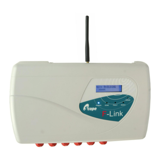
1. Introduction The Scope F-Link is a four input four output transceiver which works with up to fifteen other F-Link units to form a mesh radio network for remote alerting and status monitoring, typically of fire or security panels. A minimum of two F-Link units are required to form a system. -
Page 5: Pre-Installation
Scope. However in the absence of a full survey it is possible to carry out a basic check using a single F-Link unit. -
Page 6: Changing The Frequency Channel
F-Link Mk4 Supervised Transceiver System 2.1.3 Changing the frequency channel Use the DIP switches on the F-Link circuit board to select the required frequency channel. The F-Link will detect the change and reboot, displaying the selected frequency. All F-Links on a system must be set to use the same frequency channel. -
Page 7: Creating The F-Link Network
F-Link Mk4 Supervised Transceiver System 2.2 Creating the F-Link network The F-Link network must be created on site by ‘joining’ all F-Link Nodes to the Master. 2.2.1 Node addressing Each F-Link must have a unique address for the system to operate. One F-Link must be set as the Master (address 0) and the other F-Links set as Nodes (addresses 1-15). -
Page 8: Quiescent (Normal) Display Processor Status Icon Rotating Announcement Pulse
F-Link Mk4 Supervised Transceiver System Assuming all previous steps have been successfully followed, the F-Links will now be joined as a network and the system will be fully operational, albeit not yet installed. Each F-Link will be set up with the factory default configuration, and should display its own node name and signal meter, with no other messages or faults. -
Page 9: Priority Display
3.1.1 Antennas Never operate any Scope equipment without a suitable antenna connected. The F-Link can communicate over a considerable distance with the supplied ¼ wave antenna connected directly to the unit. On sites where difficult operating conditions exist, it may be advantageous to install remotely mounted antenna(s):... -
Page 10: Range Considerations
A Scope range test kit (part code RTESTF) is of the network so that the network monitoring can be available from your usual supplier to establish the maintained. - Page 11 F-Link Mk4 Supervised Transceiver System Detachable F-Link Configuration Record These pages should be completed, detached from the manual and left on site either with the equipment itself or with premises management. Site name ___________________________________________________________________________________ Installation Company __________________________________________________________________________ Contact phone number _________________________________________________________________________...
- Page 12 F-Link Mk4 Supervised Transceiver System Output settings Priority Zone Display Input type Node Zone Node Zone By default, all inputs are Normally Open (NO).
- Page 13 F-Link Mk4 Supervised Transceiver System Zone messages (0-7) Trigger Message Clear Message...
- Page 14 F-Link Mk4 Supervised Transceiver System Zone messages (8-15) Trigger Message Clear Message...
-
Page 15: Zone Inputs
F-Link Mk4 Supervised Transceiver System Zone inputs Each F-Link has four volt-free zone inputs, which can each be All inputs are volt-free. DO NOT configured as ‘Normally Open’ (default) or ‘Normally Closed’ using apply voltage to any input (other the configuration software. If the input is set as Normally Open (N/O) -
Page 16: Wiring Diagrams
F-Link Mk4 Supervised Transceiver System 3.2.6 Wiring diagrams Page 16 of 23 Ref: FLNK4red Issue 1... -
Page 17: Configuration
F-Link Mk4 Supervised Transceiver System 4. Configuration All F-Link units are supplied with a factory default configuration which allows a fully operational system to be created without the need for programming. Although carefully designed to be suitable for many common scenarios, the default configuration can be easily changed using the F-Link Pro Configuration Utility software (available from Scope). -
Page 18: Trigger Time
‘Network List – Write’. Un-joined Nodes must also be powered down and/or individually wiped (see section 5.5 overleaf) to fully deactivate them. Only make changes to the network list if you know what you are doing, or under the direction of Scope Technical Support staff. -
Page 19: Replacing A Node
F-Link Mk4 Supervised Transceiver System 2) Wipe the memory of the deleted Node as described in section 5.5 below (NOTE: only wipe the deleted Node). 3) Power down the Node and remove from site. It is technically possible to delete a Node without using a PC, but only by returning the entire system to factory default configuration (as described in section 5.5 below) and then recreating the network from scratch, leaving... -
Page 20: Operation
F-Link Mk4 Supervised Transceiver System 6. Operation 6.1 Normal use The F-Link network is designed to be transparent in normal use. The linked systems will communicate with each other using the F-Link as a wireless bridge. The display on each F-Link provides status information and gives details of alarm messages. -
Page 21: Replacement Keys
F-Link Mk4 Supervised Transceiver System 6.5 Replacement keys The reset/test key is an industry-standard ‘Burgess TOK 1’ type. Replacement keys are widely available from 3rd- party suppliers, or as a complete replacement switch and two keys from Scope (part code K23FBA-123). 7. Troubleshooting Symptom... -
Page 22: Index
F-Link Mk4 Supervised Transceiver System 8. Index address ............7 replacing ............... 19 aerial/antenna ..........9 noise on channel ..........21 BS5839 ............4, 10 normally open/closed ......... 8, 15 cabling............10, 16 paging ............... 4 class change .......... 8, 17, 18 PC configuration .......... -
Page 23: Specification
Operation and function via PC software (available from Scope) Footprint (mm): 330w x 190*h x 70d mm (*excluding aerial) Scope’s policy is one of continuous development. Specification is subject to change without notice. Page 23 of 23 Ref: FLNK4red Issue 1...
Need help?
Do you have a question about the F-LINK MK4 and is the answer not in the manual?
Questions and answers