Table of Contents
Advertisement
Service
Manual
SECTION
1. TECHNICAL SPECIFICATIONS ................................................................................................... 1
2. SERVICE MODE........................................................................................................................... 2
3. HOW TO DISASSEMBLE.............................................................................................................. 3
4. MAIN MICROPROCESSOR (Q120) UPDATE PROCEDURE ...................................................... 8
5. WIRING DIAGRAM ..................................................................................................................... 11
6. BLOCK DIAGRAM ...................................................................................................................... 13
7. SCHEMATIC DIAGRAM.............................................................................................................. 15
8. PARTS LOCATION...................................................................................................................... 25
9. EXPLODED VIEW AND PARTS LIST ......................................................................................... 33
10. MICROPROCESSOR AND IC DATA........................................................................................... 36
11. ELECTRICAL PARTS LIST ......................................................................................................... 46
Please use this service manual with referring to the user guide ( D.F.U. ) without fail.
TABLE OF CONTENTS
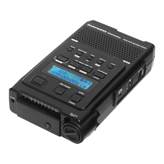
PMD660
PMD660 /
F B/N1B/U1B
Solid State Recorder
PAGE
Part no. 90M20BS855010
F i r s t I s s u e 2 0 0 5 . 0 3
MJI
Advertisement
Table of Contents

Related Manuals for Marantz PMD660/F


Summary of Contents for Marantz PMD660/F
-
Page 1: Table Of Contents
Service PMD660 / F B/N1B/U1B Manual Solid State Recorder TABLE OF CONTENTS SECTION PAGE 1. TECHNICAL SPECIFICATIONS ....................1 2. SERVICE MODE........................... 2 3. HOW TO DISASSEMBLE......................3 4. MAIN MICROPROCESSOR (Q120) UPDATE PROCEDURE ............8 5. WIRING DIAGRAM ........................11 6. - Page 2 The exchange of the lithium battery(Z001 : CR2025). (Z001 : CR2025) CAUTION Danger of explosion if battery is incorrectly replaced. Replace only with the same or equivalent type. SHOCK, FIRE HAZARD SERVICE TEST : CAUTION : After servicing this appliance and prior to returning to customer, measure the resistance between either primary AC cord connector pins ( with unit NOT connected to AC mains and its Power switch ON ), and the face or Front Panel of product and controls and chassis bottom.
-
Page 3: Technical Specifications
1. TECHNICAL SPECIFICATIONS Digital audio system General System ..........Solid State Recorder Headphone output power ......8 mW/ 16 ohms Usable media ........... CF memory cards Speaker output power ........150 mW/ 8 ohms Microdrive Phantom power ...........+48V, 5mA Recording and media methods Power consumption .mp3 ........ -
Page 4: Service Mode
2. SERVICE MODE 2. SERVICE 1. Micro-Processor(Q120) VERSION 1. Micro-Processor(Q120) Version check 1) Slide POWER switch to turn on the unit. 1) POWER 2) MENU/STORE/EDIT 2) Press MENU/STORE/EDIT button. 3) DISPLAY Preset-1 3) Preset-1 is displayed on LCD. MARK S.SKIP IN - STEREO 44.1K... -
Page 5: How To Disassemble
3. HOW TO DISASSEMBLE 1) Remove 6 screws of the bottom side. 2) Remove the battery cover and remove a screw. 3) Remove Escutcheon (The plastic board is stuck on the case with adhesives.) - Page 6 4) The bottom case of the rear panel side is raised, and the bottom case is pulled for a little in the direction of an ar- row. Cautions : When removing the bottom case, take care not damage the cable and connectors. 5) Remove 2 shafts on right and left.
- Page 7 Disassemble of the P204 Power Supply PCB P204 Power Supply PCB Remove 7 screws and disconnect 2 connector (J501). Then remove the PCB. Disassemble of the P101 Main PCB P101 Main PCB 1) Insert a thin rod to the hole at the Front panel and push REC LEVEL the REC LEVEL Knob.
- Page 8 4) Remove 2 screws and disconnect 4 connectors (J108, J110, J111, J113). 5) Disconnect a connector (J803). Then remove the PCB. Disassemble of the P201 Lcd / Sw PCB P201 Lcd / Sw PCB Remove 8 screws. Then remove the PCB.
- Page 9 Disassemble of the Front Panel. 1) Remove INPUT VR PCB on the Front panel and All the 1) INPUT VR PCB PCB on the Top case. 2) The Front panel is locked by 2 hooks (A and B). 3) Hook A and B are raised with fi ngers. The front panel can be removed,...
-
Page 10: Main Microprocessor (Q120) Update Procedure
4. MAIN MICROPROCESSOR (Q120) UPDATE 4. MAIN MICROPROCESSOR (Q120) PROCEDURE Necessary Equipment • Windows PC (Windows2000 or WindowsXP) • Windows PC (Windows2000 WindowsXP) USB cable (Series A - Series B) • (Series A - Series B) • • AC adapter •... - Page 11 4. "pmd660up.bin" of the update disk is copied to the route pmd660up.bin of Removable Disk (CompactFlash). (CompactFlash) 5. Click the "Unplug or Eject Hardware" on the task bar at 5. Windows PC Unplug or Eject Hardware Windows PC, and Click the "Stop USB Mass Storage Stop USB Mass Storage Device Device".
- Page 12 13. MPU Firmware updating will be done automatically. fi rmware 14. During the updating, "Update" is displayed on LCD with PMD660 Update blink. 15. Uploading takes about 30 seconds. 16. After Firmware rewriting is completed, the display will show the information display of initial automatically. 17.
-
Page 13: Wiring Diagram
5. WIRING DIAGRAM LCD UNIT 22P FFC J705 J704 MIC INPUT UNIT FFC CN POWER UNIT J107 J803 J502 LED SW UNIT (P203) (P204) P201 INTERNAL MIC J501 J702 J703 FFC CN 22P FFC INTERNAL MIC BATTERY CASE JJ02 J111 FFC CN J108 INPUT VR UNIT MAIN UNIT... -
Page 14: Block Diagram
6. BLOCK DIAGRAM 12.288MHz LINE IN PHANTOM POWER(48V) H.P. JACK MUTE CODEC AK4537 INPUT VR Q112 LINE OUT ATTENUATOR INT/EXT SW MIC/LINE SW AUTO/MANU SW MUTE /PHANTOM MUTE uPD77115GK-9EU PHANTOM Q113 S801 ON/OFF POWER LOGIC POWER S101 Q501/Q503/Q504/Q518 ON/OFF J105 CONNECTOR LED BUFF NJU3718AM... -
Page 15: Schematic Diagram
7. SCHEMATIC DIAGRAM (P202) P202 00MWG20BS102- INPUT VR UNIT TPF851 ROUT TPF852 LOUT TPF853 GND_A1 TPF854 TPF855 GND_A1 S6B-ZR-SM3A-TF J851 GND_A1_2 J851(P202) INPUT VR UNIT SPEAKER J109 J110 B6P-ZR-SM3A-TF S3P-ZR-SM3A-TF TPF16 TPF17 R146 MAIN UNIT C128 10u/16V R130 Q109 C132 NJM2122M (P101-1/2) R141... - Page 16 +2.5V_D1 R237 R293 1.5K +3.3V_D2 R238 TPF71 LJ13 R295 D111 R239 C188 TPF72 R215 LJ14 10u/16V 820k C271 0.01u R235 R296 TPF73 LJ15 C249 0.1u R240 R213 P101 00MWI20BS1010 R297 LJ16 TPF74 R442 OPEN C337 OPEN MAIN UNIT C195 C338 C196 0.1u OPEN...
- Page 17 LED SW UNIT JJ11 R901 R902 (P201-2/2) R903 +3.3V_D1 +3.3V_D4 GND_D1 GND_D1 +3.3V_D1 CPLD_nRES CF_CLK +3.3V_D4 JJ09 C296 SCFB3A0400 100u/6.3V TPF94 C294 0.01u C_D3 TPF95 +3.3V_D1 C_D3 DL10 DL10 C_D4 TPF96 DL11 DL11 GND_D1 C_D4 DL12 DL12 C_D5 TPF97 DL13 DL13 C_D5 DL14...
- Page 18 R502 Q518 R504 +3V_D1 74_074(1/2) DAN202K P204 00MWG20BS104- D509 R590 OPEN Q501 TC74LCX00FT POWER UNIT R589 OPEN +3.3V_D5 R541 (P204) 2.2K D508 Q503 GND_D1_1 DAN202K TC74LCX32FT R525 100k R587 Q501 Q501 Q506 R501 TC74LCX00FT TC74LCX08FT R523 MN1382S-H(TX) Q507 GND_D1_1 Q504 Q504 VOUT TC74LCX14FT...
- Page 19 R722 180K LED SW UNIT C709 R800 R801 (P201-1/2) P201 00MWG20BS101- +3.3V_A1 +3.3V_A1 R724 R727 R802 4.7K 4.7K C705 10u/6.3V C713 TPF701 Q702 GND_D1 GND_D2-1 GND_D2-1 NJM2122M TPF702 PHANTO M D701 OPEN Q701 +3.3V_A1 C704 TC74LVX4052FT R723 0.1u C714 TPF703 C701 180K 10u/6.3V...
-
Page 20: Parts Location
8. PARTS LOCATION P101 A C101 C8 C206 A6 Q102 B7 R255 A5 R381 C5 C102 C8 C208 B6 Q109 C7 R256 A5 R382 C4 C103 C7 C209 A5 Q110 B7 R271 B5 R391 B8 C104 C7 C214 C3 Q111 D4 R272 B3 R392 B8 C107 E5... - Page 21 P101 B C105 C7 C257 B4 LJ16 E6 R180 B7 R321 D4 C106 C7 C258 A5 LJ18 B3 R181 B7 R346 C4 C110 E3 C260 B5 Q103 E5 R182 B7 R347 C4 C111 E3 C261 B5 Q104 E6 R183 B7 R348 C4 C118 E4 C262 C5...
- Page 22 P201 A P201 B P202 A J851 A1 R851 A2 Sn-Ag-Cu Lead-free Solder When soldering, use the Lead-free Solder (Sn-Ag-Cu). P203 A R701 D4 R773 A2 C701 F4 D714 A4 R766 D3 S705 E3 Q701 C4 R721 D4 R741 D3 C703 C4 C725 C2 C752 D5...
- Page 23 P204 B P204 A C505 D3 C552 C2 R554 B5 C501 E2 Q504 C1 R524 C1 C506 D3 C553 C3 R559 B2 C502 E2 Q505 D3 R539 A5 C507 C2 C554 C1 R560 B3 C503 E2 Q506 C2 R549 B5 C510 C2 C555 B4 R561 B2...
-
Page 24: Exploded View And Parts List
9. EXPLODED VIEW AND PARTS LIST 5128 060B ø 2.6x8(U)x4 5128 ø 2.6x8(U)x2 020B 065B P203 P101 002B 5128 ø 2.6x8(U)x2 018B 5128 ø 2.6x6(A) P204 028G 011B 5128 P205 ø 2.6x6(A) 010B 5128 030B ø 2.6x8(U)x7 5128 P202 ø 2.6x8(U) 043B 011G 008B... - Page 25 CORRUGATED CARDBOARD CUSHION 020Z /U1B 00MZK04AS0020 UNIT KIT 64MB CF CARD (RENESAS) 022Z 00MZD01800130 CORD USB(A)-USB(B) CABLE 026Z 00D2032436006 CORD 2P PIN-3.5SP CORD (AUDIO CABLE) NOTE : "nsp" PART IS LISTED FOR REFERENCE ONLY, MARANTZ WILL NOT SUPPLY THESE PARTS.
-
Page 26: Microprocessor And Ic Data
10. MICROPROCESSOR AND IC DATA Q120 : µPD703111AGM (MAIN uP) No. PORT Function I/O DET Ext Ini Res 1 JIT1 JIT1 MODE SELECT for SSCG 2 JIT0 JIT0 MODE SELECT for SSCG 3 AVcc AVcc POWER SUPPLY for ADC(+3.3V) +3.3V 4 AVreft AVreft REFERENCE VOLTAGE for... -
Page 27: P101
Q120 : µPD703111AGM (MAIN uP) 62 A12 EXT. MEMORY ADDRESS BUS12 ROM/RAM 63 A11 EXT. MEMORY ADDRESS BUS11 ROM/RAM 64 A10 EXT. MEMORY ADDRESS BUS10 ROM/RAM 65 A9 EXT. MEMORY ADDRESS BUS9 ROM/RAM 66 A8 EXT. MEMORY ADDRESS BUS8 ROM/RAM 67 A7 EXT. -
Page 28: P101
Q120 : µPD703111AGM (MAIN uP) 123 PDH9/D25/_INTPD9/TIUD10 CF_OP CF DOOR CF DOOR 124 PDH10/D26/_INTPD10/ EJECTnINT CF EJECT CPLD INTP110/TCUD11 125 PDH11/D27/_INTPD11/ AC_IN AC IN POWER UNIT INTP111/TCLD11 126 PDH12/D28/_INTPD12/TO11 USB IN CONNECTER 127 PDH13/D29/_INTPD13/TIUD11 nLBO NO USE PAH9(P45) 128 EVdd EVdd POWER SUPPLY(+3.3V) +3.3V... - Page 29 Q113 : µPD77115 (DSP)
- Page 30 Q112 : AK4537(CODEC)
- Page 31 Q112 : AK4537(CODEC)
- Page 32 Q118 : CDCV304PW(140-MHz PCI-X CLOCK BUFFER) FUNCTION TABLE INPUTS OUTPUT CLKIN 1Y (0:3) functional block diagram Logic Control CLKIN Q119 : NJU6350B(REAL TIME CLOCK)
- Page 33 Q507 : MN1382S-H Block Diagram Voltage Reference 1 Comparator – Level Converter Output Circuit Comparator Voltage – Reference 2 Note * 1 : Circuits vary slightly depending on the output type (CMOS output, N-channel open drain output, or inverted CMOS output) Pin Descriptions Pin No.
- Page 34 Q501 : TC74LCX00FT Q121 / Q506 : TC74LCX08FT Q122 / Q504 : TC74LCX14FT Q503 : TC74LCX32FT...
- Page 35 Q518 : TC74LCX74FT Q123 : TC74LCX125FT Q103 / Q105 / Q107 / Q701 / Q704 : TC74LVX4052FT...
-
Page 36: Electrical Parts List
11. ELECTRICAL PARTS LIST NOTE ON SAFETY FOR FUSIBLE RESISTOR : PARTS INFORMATION RESISTORS The suppliers and their type numbers of fusible resistors 1) 00MGD05 × × × 140, Carbon film fixed resistor, ±5% 1/4W are as follows; 2) 00MGD05 × × × 160, Carbon film fixed resistor, ±5% 1/6W 1. - Page 37 47 PF +- 5% CG 50V GR39 P101 C169 00MDD95470300 CER. CAP. 47 PF +- 5% CG 50V GR39 P101 C170 00MDK98104200 CER. CAP. GRM39F104Z16 0.1UF MURATA NOTE : "nsp" PART IS LISTED FOR REFERENCE ONLY, MARANTZ WILL NOT SUPPLY THESE PARTS.
- Page 38 47 PF +- 5% CG 50V GR39 P101 C239 00MDD95470300 CER. CAP. 47 PF +- 5% CG 50V GR39 P101 C240 00MDK96102300 CER. CAP. 1000 PF +- 10% B 50V GR36 NOTE : "nsp" PART IS LISTED FOR REFERENCE ONLY, MARANTZ WILL NOT SUPPLY THESE PARTS.
- Page 39 0.01 UF +- 10% B 16V GRM36 P101 C321 00MDK06103200 00MDK06103200 CER. CAP. 0.01 UF +- 10% B 16V GRM36 P101 C322 00MDK98103300 CER. CAP. GRM39F103Z16 0.01UF MURATA NOTE : "nsp" PART IS LISTED FOR REFERENCE ONLY, MARANTZ WILL NOT SUPPLY THESE PARTS.
-
Page 40: Q120(P101
S-24C01BFJ-TB P101 Q118 00MHC10144370 00MHC10144370 IC CDCV304PWR P101 Q119 00MHC12251090 00MHC12251090 IC NJU6350R P101 Q120 00D2623468001 00D2623468001 U-PRO UPD703111GM-10 P101 Q121 00MHC10475050 00MHC10475050 IC TC74LCX08FT NOTE : "nsp" PART IS LISTED FOR REFERENCE ONLY, MARANTZ WILL NOT SUPPLY THESE PARTS. - Page 41 100 OHM +- 5% 1/16W P101 R157 00MNN05104610 CHIP RES. 100K OHM +- 5% 1/16W P101 R158 00MNN05104610 CHIP RES. 100K OHM +- 5% 1/16W NOTE : "nsp" PART IS LISTED FOR REFERENCE ONLY, MARANTZ WILL NOT SUPPLY THESE PARTS.
- Page 42 47K OHM +- 5% 1/16W P101 R233 00MNN05000610 CHIP RES. 0 OHM +- 5% 1/16W P101 R234 00MNN05000610 CHIP RES. 0 OHM +- 5% 1/16W NOTE : "nsp" PART IS LISTED FOR REFERENCE ONLY, MARANTZ WILL NOT SUPPLY THESE PARTS.
- Page 43 22 OHM +- 5% 1/16W P101 R317 00MNP05220610 00MNP05220610 CHIP RES. 22 OHM +- 5% 1/16W P101 R318 00MNP05220610 00MNP05220610 CHIP RES. 22 OHM +- 5% 1/16W NOTE : "nsp" PART IS LISTED FOR REFERENCE ONLY, MARANTZ WILL NOT SUPPLY THESE PARTS.
- Page 44 22 OHM +- 5% 1/16W P101 R384 00MNP05220610 00MNP05220610 CHIP RES. 22 OHM +- 5% 1/16W P101 R385 00MNP05220610 00MNP05220610 CHIP RES. 22 OHM +- 5% 1/16W NOTE : "nsp" PART IS LISTED FOR REFERENCE ONLY, MARANTZ WILL NOT SUPPLY THESE PARTS.
- Page 45 100 PF +- 5% CG 50V GR39 P201 C708 00MDD95101300 CER. CAP. 100 PF +- 5% CG 50V GR39 P201 C709 00MDD95120300 CER. CAP. 12 PF +- 5% CG 50V NOTE : "nsp" PART IS LISTED FOR REFERENCE ONLY, MARANTZ WILL NOT SUPPLY THESE PARTS.
- Page 46 00D2760819908 CHIP DIODE UDZSTE-172.7B P201 D709 00D2760819908 00D2760819908 CHIP DIODE UDZSTE-172.7B P201 D710 00D2760819908 00D2760819908 CHIP DIODE UDZSTE-172.7B P201 D711 00D2760819908 00D2760819908 CHIP DIODE UDZSTE-172.7B NOTE : "nsp" PART IS LISTED FOR REFERENCE ONLY, MARANTZ WILL NOT SUPPLY THESE PARTS.
- Page 47 4.7K OHM +- 5% 1/16W P201 R726 00MNN05472610 CHIP RES. 4.7K OHM +- 5% 1/16W P201 R727 00MNN05472610 CHIP RES. 4.7K OHM +- 5% 1/16W NOTE : "nsp" PART IS LISTED FOR REFERENCE ONLY, MARANTZ WILL NOT SUPPLY THESE PARTS.
- Page 48 0 OHM +- 5% 1/16W P201 R794 00MNN05561610 CHIP RES. 560 OHM +- 5% 1/16W P201 R796 00MNN05000610 CHIP RES. 0 OHM +- 5% 1/16W NOTE : "nsp" PART IS LISTED FOR REFERENCE ONLY, MARANTZ WILL NOT SUPPLY THESE PARTS.
- Page 49 00MDK98105200 CER. CAP. 1UF/10V F P204 C528 00MEY10601620 00MEY10601620 ELECT CAP. 10UF/16V P204 C529 00MDK98104200 CER. CAP. GRM39F104Z16 0.1UF MURATA P204 C530 00MDK98105200 CER. CAP. 1UF/10V F NOTE : "nsp" PART IS LISTED FOR REFERENCE ONLY, MARANTZ WILL NOT SUPPLY THESE PARTS.
- Page 50 00MHC10063360 00MHC10063360 IC LM2663M P204 Q516 00MHC12259990 00MHC12259990 IC MAX1522EUT-T P204 Q517 00MHY22231010 00MHY22231010 CHIP FET 2SK2231 P204 Q518 00MHC012005K0 00MHC012005K0 IC TC74LCX74FT DUAL D-TYPE FLIP-FLOP NOTE : "nsp" PART IS LISTED FOR REFERENCE ONLY, MARANTZ WILL NOT SUPPLY THESE PARTS.
- Page 51 0 OHM +- 5% 1/16W DETECTOR SW PCB (00MWG20BS205-) P205 C901 00MDK98104200 CER. CAP. GRM39F104Z16 0.1UF MURATA P205 S901 00MSP01012420 00MSP01012420 PUSH SW DETECT SW ESE11SV1 NOTE : "nsp" PART IS LISTED FOR REFERENCE ONLY, MARANTZ WILL NOT SUPPLY THESE PARTS.
Need help?
Do you have a question about the PMD660/F and is the answer not in the manual?
Questions and answers