Advertisement
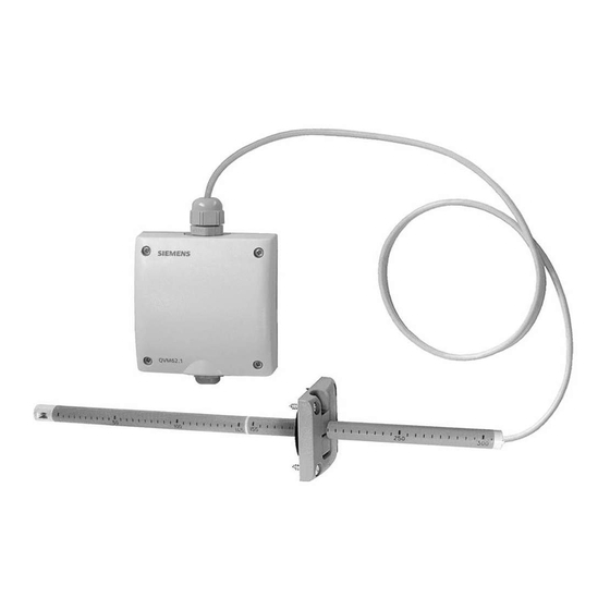
QVM62.1 Air Velocity Sensor
Product Description
This sensor is used to measure the air velocity in a
duct and provide a 0 to 10V signal to a controller
that is proportional to the velocity. This allows the
controller to maintain a constant airflow in the duct,
balance out pressure fluctuations (supply or exhaust
air control), or just monitor the flow in a duct. The Air
Velocity Sensor is generally used for modulating fan
control in primary applications to set the basic
volume flow.
Product Number
QVM62.1
Warning/Caution Notations
WARNING:
CAUTION:
Required Tools
•
Pencil
•
Hammer
•
Center hole punch
•
Screwdrivers
•
Four - #8 × 1/2-inch sheet metal screws
•
Electric drill with 1/8-inch and 7/8-inch
drill bits
Expected Installation Time
45 minutes
Prerequisites
Field wiring must be pulled to installation location.
Item Number 129-095, Rev. AA
Personal injury/loss of life may
occur if you do not follow the
procedures as specified.
Equipment damage or loss of
data may occur if you do not
follow the procedures as
specified.
Installation Instructions
Installation
Probe Mounting Flange and Sensor
1.
Determine the depth of insertion required for
the probe and assemble the extension tube
and/or probe end cap onto the primary sensor
head tube.
NOTE: If the insertion depth required is less
than or equal to 5.7 inches (145 mm)
the extension tube may be removed by
disconnecting the probe cable at the
transducer head, and sliding the
extension tube off the cable. (With the
extension tube installed, the probe's
depth of insertion is 11.8 inches
[300mm].) If the extension tube is
removed, be sure to reinstall the
probe's end cap on the cable before
rewiring it to the transducer head.
2. Position the probe mounting flange on the duct
where will be installed. Lightly tap the screw
heads to create drill marks for the mounting
screw holes.
NOTE: Install the sensor in the ductwork in a
location where the airflow is not
turbulent. Do not place it close to
dampers, registers, or bends in
ductwork.
Figure 1. Mounting Locations.
Document No. 129-095
September 24, 2009
Page 1 of 3
Advertisement
Table of Contents

Related Manuals for Siemens QVM62.1


Summary of Contents for Siemens QVM62.1
-
Page 1: Product Description
Installation Instructions Document No. 129-095 September 24, 2009 QVM62.1 Air Velocity Sensor Installation Product Description Probe Mounting Flange and Sensor This sensor is used to measure the air velocity in a Determine the depth of insertion required for duct and provide a 0 to 10V signal to a controller the probe and assemble the extension tube that is proportional to the velocity. - Page 2 6. Connect the Field wiring to the transducer head 9. Tighten the mounting screw located on the side connector (see Figure 3.) of the mounting flange (see Figure 4). The installation is now complete. Page 2 of 3 Siemens Industry, Inc.
- Page 3 Information in this publication is based on current specifications. The company reserves the right to make changes in specifications and models as design improvements are introduced. Product or company names mentioned herein may be the trademarks of their respective owners. © 2009 Siemens Industry, Inc.
Need help?
Do you have a question about the QVM62.1 and is the answer not in the manual?
Questions and answers