Advertisement
Quick Links
WARNING
!
Read this Manual BEFORE using this equipment.
Failure to read and follow all safety and use information can result in death,
serious personal injury, property damage, or damage to the equipment.
Keep this Manual for future reference.
WARNING
!
FAILURE TO COMPLY WITH PROPER INSTALLATION AND
MAINTENANCE INSTRUCTIONS COULD CONTRIBUTE TO THE
VALVE FAILURE, RESULTING IN INJURY AND/OR DEATH.
TO ENSURE THE ACCURATE AND RELIABLE OPERATION OF THIS
PRODUCT, IT IS ESSENTIAL TO:
• Properly design the system to minimize pressure and temperature varia-
tions.
• This valve is factory preset. However, it can be adjusted to deliver scald-
ing temperatures. Check outlet temperature to ensure it does not
exceed 105°F (41°C). Make sure temperature limit stop is properly
re-set to maximum 105°F (41°C) following valve maintenance or repair.
Tampering with limit stop in any way may result in scalding temperature
causing serious bodily harm and/or death.
WARNING
!
Need for Periodic Inspection and Yearly Maintenance: Periodic
inspection and yearly maintenance by a licensed contractor is required.
Corrosive water conditions, and/or unauthorized adjustments or repair
could render the valve ineffective for service intended. Regular checking
and cleaning of the valve's internal components and check stops helps
assure maximum life and proper product function. Frequency of cleaning
and inspection depends upon local water conditions.
WARNING
!
You are required to consult the local building and plumbing codes prior
to installation. If the information in this manual is not consistent with local
building or plumbing codes, the local codes should be followed. Inquire with
governing authorities for additional local requirements.
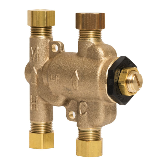
Description
The Watts
3
⁄
" (10mm)compression fitting and quick-connect mixing thermo-
8
static valve maintains and limits hot water to desired selectable temperature
between 80°F to 120°F (27°C to 49°C) and with flow rate as low as 0.25
gpm (1.0 lpm) and as high as 2.25 gpm (8.5 lpm). The mixing valve is listed
to ASSE 1070 standard and IAPMO cUPC. The superior flow characteristic
of LFUSG-B series provides temperature control with low pressure drop.
The LFUSG-B incorporate dual check valves to protect against cross-flow
and integral screens to filter out debris. A cap is included for three port
applications.
Applications
The LFUSG-B are intended for under sink installations to control the hot
water temperature and minimize the occurrence of accidental scalding. The
water temperature must be adjusted by the installer using a thermometer to
measure the hot water temperature at the faucet outlet. Maximum tempera-
ture of 105°F (41°C) is recommended.
Sensor Faucet
Watts
LFUSG-B-M2
Installation
NOTICE
Flush all piping thoroughly before installation.
1. Locate suitable place for the tempering valve. Valve should be accessible
for service and adjustment and as close to the point-of-use as possible.
2. Connect hot and cold water to the supply valve using
3
⁄
" compression
8
connections. Make sure copper tubing does
not extend more than
⁄
" beyond the com-
3
16
pression ferrule.
For quick-connect refer to quick-connect
installation.
3. Connect outlets of tempering valve to fixture
inlets.
4. Turn hot and cold water supplies on. If any
leaks are observed, tighten
LFUSG-B-M2
connections as necessary before proceeding.
5. Turn on fixture and allow water to flow for 2
minutes. Measure temperature at the outlet.
If water is not at desired temperature, adjust as
necessary (see temperature adjustment section).
Two Handle Faucet
ASSE 1070 and cUPC Listed
Temperature Adjustment
ASSE 1070
1. Loosen locknut
2. Turn on fixture and run water at least for 2 minutes to allow water
temperature to stabilize.
3. Turn temperature adjustment screw counterclockwise for hotter or
clockwise for colder outlet temperature.
4. Tighten locknut to prevent accidental or unauthorized temperature
adjustment.
5. Re-check outlet temperature.
Quick-Connect Installation
To Connect:
To Disconnect:
PEX tubing only
1. Remove collet clip.
2. Depress collet.
3. Pull tubing from
1 in. (25.4mm)
tailpiece.
3
⁄
in. Pipe (0.95mm)
8
Pipe Stiffener
Tail Piece
1. Mark pipe as shown.
3. If using PEX tubing, insert pipe stiff-
ener (provided) into end of pipe.
This is pipe insertion
depth.
4. Push tubing into tailpiece up to mark.
2. Clean pipe end.
5. Insert collet clip.
Basic Construction
Ferrule
Compression
Nut
Body
Plunger
Locking Nut
Temperature
Adjustment
Screw
Spring
Thermostat
Check module
Screen
Advertisement

Related Manuals for Watts Under Sink Guardian LFUSG-B-M2


Summary of Contents for Watts Under Sink Guardian LFUSG-B-M2
- Page 1 Description Installation Quick-Connect Installation Read this Manual BEFORE using this equipment. NOTICE The Watts ⁄ " (10mm)compression fitting and quick-connect mixing thermo- To Connect: To Disconnect: Failure to read and follow all safety and use information can result in death, static valve maintains and limits hot water to desired selectable temperature Flush all piping thoroughly before installation.
- Page 2 Rejilla Description AVERTISSEMENT Installation Installation du raccord rapide Le régulateur thermostatique à raccord rapide et de compression Watts de Lisez attentivement ce manuel avant d'utiliser cet équipement. AVIS Purgez toute la tuyauterie à fond avant l’installation. Raccordement : 10 mm ( ⁄...
Need help?
Do you have a question about the Under Sink Guardian LFUSG-B-M2 and is the answer not in the manual?
Questions and answers