Table of Contents
Advertisement
SAFETY-RELATED COMPONENT WARNING!!
COMPONENTS IDENTIFIED BY MARK
SCHEMATIC DIAGRAM AND IN THE PARTS LIST
ARE CRITICAL FOR RISK OF FIRE AND ELEC-
TRIC SHOCK. REPLACE THESE COMPONENTS
WITH ONKYO PARTS WHOSE PARTS NUMBERS
APPEAR AS SHOWN IN THIS MANUAL.
MAKE LEAKAGE-CURRENT OR RESISTANCE
MEASUREMENTS TO DETERMINE THAT EXPO-
SED PARTS ARE ACCEPTABLY INSULATED FORM
THE SUPPLY CIRCUIT BEFORE RETURNING THE
APPLIANCE TO THE CUSTOMER.
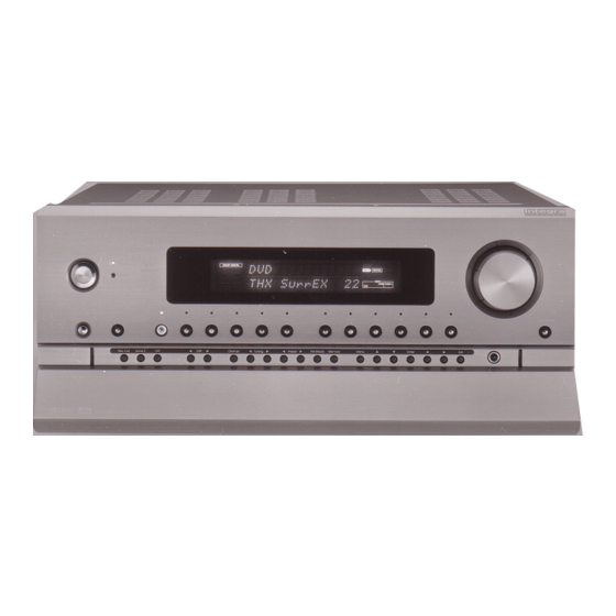
AV Controller
MODEL RDC-7
Silver model
120V AC, 60Hz
UDD, UDT
230V AC, 50Hz
UPP,UPT
UGT
220 -230V AC, 50/60Hz
TABLE OF CONTENTS
SPECIFICATIONS--------------------------------------------------------
ON THE
SERVICE PROCEDURE-------------------------------------------------
FRONT PANEL FACILITIES--------------------------------------------
REMOTE CONTROLLER-----------------------------------------------
REAR PANEL FACILITIES------------------------------------------------
CONNECTING POWER AMPLIFIERS---------------------------------
DISASSEMBLING PROCEDURES---------------------------------------
ASSEMBLING PROCEDURES--------------------------------------------
IC BLOCK DIAGRAMS AND DESCRIPTIONS----------------------
WIRING VIEW--------------------------------------------------------------
CHASSIS EXPLODED VIEW--------------------------------------------
CHASSIS EXPLODED VIEW PARTS LIST-----------------------------
MAIN MICROPROCESSOR CONNECTION DIAGRAM-----------
SUB MICROPROCESSOR CONNECTION DIAGRAM-------------
SUB MICROPROCESSOR TERMINAL DESCRIPTION------------
PC BOARD CONNECTION VIEW---------------------------------------
BLOCK DIAGRAM--------------------------------------------------------
PRINTED CIRCUIT BOARD PARTS LIST--------------------
CONFIRMATION-----------------------------------------------------------
FL TUBE VIEW--------------------------------------------------------------
PACKING VIEW--------------------------------------------------------------
PRINTED CIRCUIT BOARD VIEW-----------------
RDC-7
No.3653
Sep,2000
2
3
4
5
6
8
10
11
12
13~30
31
33
35
37
39
41
43
45
47
49
50~94
95
96
97
Advertisement
Table of Contents

Related Manuals for Integra RDC-7


Summary of Contents for Integra RDC-7
-
Page 1: Table Of Contents
RDC-7 No.3653 Sep,2000 AV Controller MODEL RDC-7 Silver model 120V AC, 60Hz UDD, UDT 230V AC, 50Hz UPP,UPT 220 -230V AC, 50/60Hz TABLE OF CONTENTS SAFETY-RELATED COMPONENT WARNING!! SPECIFICATIONS-------------------------------------------------------- COMPONENTS IDENTIFIED BY MARK ON THE SERVICE PROCEDURE------------------------------------------------- FRONT PANEL FACILITIES--------------------------------------------... -
Page 2: Specifications
RDC-7 SPECIFICATIONS GENERAL CONTROLLER SECTION Power Supply AC 120 V, 60 Hz Input Sensitivity and Impedance AC 230 V, 50 Hz PHONO 2.5 mV, 50 kohms AC 220 V, 50/60 Hz LINE (CD, TAPE 1-2, DVD, Power Consumption 75 W... -
Page 3: Service Procedure
RDC-7 SERVICE PROCEDURE 1. Replacing the fuses 5. Changing the AM band step When you change the band step, change the parts as shown below. This symbol located near the fuse indicates that the To 10kHz To 9kHz fuse used is show operating type, For continued protection against... -
Page 4: Front Panel Facilities
Front panel facilities Here is an explanation of the controls and displays on the front panel of the RDC-7. Front panel Digital format: The current input source is set for Front panel Power a digital format of Ò Auto.Ó After plugging in the power cord into the rear panel and... -
Page 5: Remote Controller
STNBY scans when performing a PTY or TP scan with the RDS formed at the remote controller. Turns the RDC-7 in standby. Be aware that broadcasts. pressing the STNBY button only places the RDC-7 in standby and does not turn the power RT/PTY/TP (European models only) completely off. -
Page 6: Rear Panel Facilities
¥ Be sure to always refer to the instructions that came ANTENNA COMPONENT VIDEO INPUT/OUTPUT rear of the RDC-7 and how they are used. Before with the component that you are connecting. These jacks are for connecting the FM indoor antenna... - Page 7 These outputs are activated by the Zone 2 button on compact disc players that also have Integra/OnkyoÕ s erly connect the RDC-7 to the peripheral device. of the RDC-7 so that it will be able to support new digi- connectors. Simply connect a remote control cable the front panel.
-
Page 8: Example Of How To Connect Your Equipment
VIDEO Speaker configuration and placement: RS 232 DIGITAL Radio antenna: INPUT 12V TRIGGER IR IN PHONO VIDEO Enjoying the RDC-7 from a remote room (Zone 2): (OPTICAL) MAIN ZONE 2 VIDEO S VIDEO Turntable Default setting (PHONO) Input source Digital input... - Page 9 Below is an example of how you can connect your the output terminals (PLAY) of the device to the TAPE 1 to the VIDEO 4 IN jack on the RDC-7. If there is an S- the video output terminal (composite) on the device to audio components to the RDC-7.
-
Page 10: Connecting Power Amplifiers
Connect your power amplifier to the PRE OUT jacks on Connect your power amplifier to the PRE OUT jacks on the RDC-7. If the jacks on your power amplifier are RCA the RDC-7. If the jacks on your power amplifier are XLR... -
Page 11: Disassembling Procedures
RDC-7 DISASSEMBLING PROCEDURES 2. Front panel assembly 1. Top cover Remove the top cover. Remove two screws A holding the top cover and bracket. Disconnect two FFCs on the sockets of P7201B and P7202A. Remove six screws B holding the top cover and chassis. -
Page 12: Assembling Procedures
RDC-7 ASSEMBLING PROCEDURES 3. Attachment of door 1. Attachment of door knob Put the cushions according to the center of rib. When you replace the door knob assembly of lef side, cut the two knobs below. Cushion Inlay the door base to the door. - Page 13 RDC-7 Q8704 : XCS05XL-4VQ100C Pin Descriptions Pin No. 12, 25, 51 63, 75, 89 1, 11, 23, 38 49, 64, 77, 88...
- Page 14 RDC-7 Pin Descriptions Pin No. 2, 27, 54, 79 21, 48, 73, 99...
- Page 15 RDC-7 Q728,Q768: MBM29LV002/004TC-910PTN (Flash memory) BLOCK DIAGRAM to DQ RY/BY RY/BY Buffer Erase Voltage Input/Output Generator Buffers State Control RESET Command Register Program Voltage Generator Chip Enable Data Latch Output Enable Logic Y-Decoder Y-Gating Timer for Address Low V Detector...
- Page 16 RDC-7 Q8701 : CC1536E (MASTER CLOCK MODULE) +5VD +5V VCO +5VD DOWN (1024/1536FSBUF) (512/736FSBUF) 5050 INPUT/OE2(GCLK2) INPUT/GCLRn .047uF INPUT/OE1n INPUT/GCLK1 VCOOUT NOT ON PC BOARD +5VD +5VD PROGTCK +5VD PROGTDO PROGTMS PROGTDI 11VREGEN VCOREGEN DOWN 100k +5V VCO BSS84ZXC 11VREGEN .1uF...
-
Page 17: Wiring View
RDC-7 WIRING VIEW S VIDEO VIDEO DIGITAL DIGITAL DIGITAL DIGITAL AC-3 OUTPUT INPUT OUTPUT INPUT MONITOR VIDEO VIDEO VIDEO VIDEO VIDEO MONITOR VIDEO VIDEO VIDEO VIDEO VIDEO PRE OUT ZONE2 (COAXIAL) ZONE2 SUBWOOFER CENTER LEFT RIGHT P4711A SUBWOOFER P2024 NAAF-6814... -
Page 18: Chassis Exploded View
RDC-7 RDC-7 CHASSIS EXPLODED VIEW The special screw (Ref.No. ) is included P3006 in the socket assembly. P3005 P3005a P2525 P7201 P7202 P1201 F9004 F9002 F9001 P772 T9001... -
Page 19: Chassis Exploded View Parts List
RDC-7 CHASSIS EXPLODED VIEW PARTS LIST <UDD> 120V model only NOTE: <UDT> Asian model only for 120V NOTE: THE COMPONENTS IDENTIFIED BY MARK <UPT> Asian model only for 230V <UPP> European model only CRITICAL FOR RISK OF FIRE AND ELECTRIC SHOCK. -
Page 20: Main Microprocessor Connection Diagram
RDC-7 RDC-7 MAIN MICROPROCESSOR CONNECTION DIAGRAM Q4214 16 STB Q4210 16 STB TUNER UNIT Q4010 TC9482F TC9482F Q7201 M30624F Q3220 15 DATA 15 DATA TC9163AF ELECTRONIC VOLUME 23 FUNC ELECTRONIC VOLUME TC9274AF-008 14 CK 14 CK SUB MICROPROCESSOR FRONT L/R... -
Page 21: Main Microprocessor Terminal Description
MAIN MICROPROCESSOR TERMINAL DESCRIPTION Q7001 : M30624FGFP Function Act. Description FDATA Serial data output terminal of function switch for input and configuration. Serial clock output terminal of function switch for input and configuration. FCLK CFSTB Serial clock output terminal of function switch for configuration. TDATA Serial data output terminal of tone control IC. - Page 22 RDC-7 Function Act. Description Sampling frequency control output terminal for Gate array (Q8704) Sampling frequency control output terminal for Gate array (Q8704) TUMUT Muting control output terminal for tuner section. MRMUT Muting control output terminal for zone 2. HPMUT Muting control output terminal for headphone.
-
Page 23: Sub Microprocessor Connection Diagram
RDC-7 RDC-7 SUB MICROPROCESSOR Q2201 CONNECTION DIAGRAM Q2901 Q2951 Q2952 Q7401 Q7001 ON-SCREEN VIDEO CONTROL VIDEO VIDEO FL TUBE MAIN MICROPROCESSOR DISPLAY CONTROL SWITCH SELECTOR SELECTOR 30-BT-03G U7201 LC74761-9189 TC9162AF SW TC9163AF SW TC9164AF REMOTE CONTROL SENSOR INPUT/OUTPUT Q7402 Q7403... -
Page 24: Sub Microprocessor Terminal Description
SUB MICROPROCESSOR TERMINAL DESCRIPTION Q7201 : M30624FGFP Function Act. Description FLS0/OSDSO Serial data output terminal for FL tube driver and on-screen ICs. FLSCK/OSDSCK Serial clock output terminal for FL tube driver and on-screen ICs. FLCS2 Chip selection output for FL tube driver IC 2. FLCS1 Chip selection output for FL tube driver IC 1. - Page 25 RDC-7 Function Act. Description Control output terminal for Tape 1 recording or Zone 2 LED. TP1_RZLED FM_RZLED Control output terminal for FM recording or Zone 2 LED. AM_RZLED Control output terminal for AM recording or Zone 2 LED. PHO_RZLED Control output terminal for Phono recording or Zone 2 LED.
-
Page 26: Pc Board Connection View
RDC-7 RDC-7 PC BOARD CONNECTION VIEW NADG-6830 P2024 P2524 DSP CIRCUIT PC BOARD NAVD-6849 NAVD-6848 VIDEO CIRCUIT S VIDEO TERMINAL PC BOARD PC BOARD P705 P704 P703 P702 P701 P2012 P2013 P2011 P2013 P2012 P2011 NAVD-6850 COMPONENT VIDEO P2512A P2011A... -
Page 27: Block Diagram
BLOCK DIAGRAM... -
Page 28: Printed Circuit Board Parts List
RDC-7 PRINTED CIRCUIT BOARD PARTS LIST <UDD> 120 V model only NOTE: <UDT> Asian model only for 120 V NOTE: THE COMPONENTS IDENTIFIED BY MARK <UPT> Asian model only for 230 V CRITICAL FOR RISK OF FIRE AND ELECTRIC SHOCK. -
Page 29: Schematic Diagram 1
RDC-7 SCHEMATIC DIAGRAM 1 INPUT/OUTPUT SELECTOR SCHEMATIC DIAGRAM (NAAF-6813) - Page 30 RDC-7 RDC-7 SCHEMATIC DIAGRAM 2 INPUT/OUTPUT SELECTOR SCHEMATIC DIAGRAM (NAAF-6813)
- Page 33 RDC-7 RDC-7 SCHEMATIC DIAGRAM 5 DSP CIRCUIT SCHEMATIC DIAGRAM (NADG-6830) P171 REC.OUT COAX.1 COAX.2 P172 COAX.3 COAX.4 COAX.5 P173 AC-3 RF...
-
Page 34: Printed Circuit Board View 4
RDC-7 PRINTED CIRCUIT BOARD VIEW 4 DSP CIRCUIT PC BOARD (NADG-6830) DSP CIRCUIT PC BOARD (NADG-6830-2) CIRCUIT NO. PART NO. DESCRIPTION CIRCUIT NO. PART NO. DESCRIPTION CIRCUIT NO. PART NO. DESCRIPTION Photo couplers Crystals Q818 222780053R2JR NJM78L05UA U171 24120079 GP1F38T2, Photo interrupter 3010279R2 XTL-18.432M... - Page 35 RDC-7 RDC-7 SCHEMATIC DIAGRAM 6 DISPLAY & SUB-MICROPROCESSOR SCHEMATIC DIAGRAM (NADIS-6832) HEADPHONE JACK SCHEMATIC DIAGRAM (NAETC-6834) OPERATION SWITCH SCHEMATIC DIAGRAM (NASW-6833)
- Page 36 RDC-7 OPERATION SWITCH PC BOARD (NASW-6833) Soldering side R7637 Component side R7638 JL7601B R7639 JL7601B DISPLAY & SUB MICROPROCESSOR PC BOARD (NADIS-6832-1F/1G/1H/1I) CIRCUIT NO. PART NO. DESCRIPTION CIRCUIT NO. PART NO. DESCRIPTION FL tube Socket AS Q7401 212208 P7451A 2002E391215...
- Page 37 RDC-7 MAIN MICROPROCESSOR PC BOARD (NAAR-6837-1F/1G/1H) CIRCUIT NO. DESCRIPTION DESCRIPTION CIRCUIT NO. PART NO. PART NO. Plugs Q1502 NPLG-4P587 22241297R2 BU1923F <UPP> JL8002B 25055625 NPLG-5P588 Q1701 JL9221B 25055626 222780125JRCW NJM78M12FA NPLG-10P593 Q1702 JL9222B 25055631 222780053JRC NJM78L05A NPLG-10P394 P2011A,P2013A 25055412 Q2901...
- Page 38 RDC-7 RDC-7 SCHEMATIC DIAGRAM 7 MAIN MICROPROCESSOR SCHEMATIC DIAGRAM (NAAR-6837)
- Page 39 RDC-7 VIDEO CIRCUIT PC BOARD (NAVD-6848-1F/1G) CIRCUIT NO. PART NO. DESCRIPTION CIRCUIT NO. PART NO. DESCRIPTION Jacks Q2001,Q2002 222740515R2 74HC4051AF P2001,P2002 25045566 NPJ-4PDYE381 P2003 25045363 NPJ-3PDYE208 Q2011,Q2111,Q2151 22241441R2 MAX4016ESA Q2171, Q2521 22241441R2 MAX4016ESA P2011,P2013,P2521 25050678 NSCT-10P482 Q2201 22241037 LC74761-9189 P2012...
- Page 40 RDC-7 RDC-7 SCHEMATIC DIAGRAM 8 S VIDEO TERMINAL SCHEMATIC VIDEO CIRCUIT SCHEMATIC DIAGRAM (NAVD-6848) DIAGRAM (NAVD-6849) NAVD-6848 NAVD6849...
-
Page 41: Printed Circuit Board View
RDC-7 RDC-7 SCHEMATIC DIAGRAM 9 PRINTED CIRCUIT BOARD VIEW 9 COMPONENT VIDEO TERMINAL SCHEMATIC DIAGRAM (NAVD-6850) COMPONENT VIDEO TERMINAL PC BOARD (NAVD-6850) COMPONENT VIDEO TERMINAL PC BOARD (NAVD-6850-1F/1G) CIRCUIT NO. PART NO. DESCRIPTION Q2801,Q2811 222740525R2 74HC4052AF Q2802 22241442R2 MAX4218ESD Transistors... - Page 42 D / A CONVERTER CIRCUIT PC BOARD (NAVD-6860-2) CIRCUIT NO. DESCRIPTION CIRCUIT NO. PART NO. DESCRIPTION PART NO. Capacitors Photocouplers Q6201,Q6211 ON313 or C6201,C6211,C6921 374722234 0.022 F 5 %, 50 V, Plastic 24120080 or 393321017 100 F, 6.3 V, Elect. 24120043 ON313 C6202...
- Page 43 RDC-7 CIRCUIT NO. PART NO. DESCRIPTION Thermistors R6233-R6243 4000195 RXE030 R8095 ,R8195 4000200 RXE030 R8295, R8395 4000200 RXE030 Resistors R8091,R8191,R8291 453530224 5 %, 1/2 W, Metal oxide R8096,R8196 453530474 5 %, 1/2 W, Metal oxide R8296,R8396 443521204 5 %, 1/2 W, Metal oxide...
- Page 44 RDC-7 RDC-7 SCHEMATIC DIAGRAM 10 D/A CONVERTER CIRCUIT SCHEMATIC DIAGRAM (NADG-6860) +12V IR IN TRGA MAIN TRGB IR MAIN ZONE2 ZONE2...
- Page 45 RDC-7 XLR JACK PC BOARD (2) (NAAF-6862-2F/2G/2H/2I) XLR JACK PC BOARD(1) (NAAF-6861-2F/2G/2H/2I) CIRCUIT NO. PART NO. DESCRIPTION CIRCUIT NO. PART NO. DESCRIPTION Q5800,Q5801 22241472R2 NJM2114M-D Q5802-Q5805 22241472R2 NJM2114M-D Q5806,Q5807 22241472R2 NJM2114M-D Transistors Transistors Q5811-Q5815 2213632 or RN1241-B or Q5810, Q5816 ,Q5817...
- Page 46 RDC-7 RDC-7 SCHEMATIC DIAGRAM 11 XLR JACK SCHEMATIC DIAGRAM (NAAF-6862) XLR JACK SCHEMATIC DIAGRAM (NAAF-6861)
-
Page 47: Confirmation
CONFIRMATION 1.TEST MODE 1. Turn POWER switch to set the the unit to standby state. The STANDBY indicator will light up. 2. Press STANDBY/ON button to turn on the unit. The display will light up and the STANDBY indicator will turn off. 3. -
Page 48: Fl Tube View
RDC-7 FL TUBE VIEW Q7401 : 30-BT-03G SLEEP DOLBY DIGITAL TAPE-2 MONITOR MPEG DIGITAL ANALOG INPUT DOLBY PRO LOGIC AC-3RF IEEE1394 STEREO OPTICAL 1 2 3 4 SOURCE DIRECT COAXIAL 1 2 3 4 VIDEO COMPONENT MIDNIGHT THEATER 1 2 3 4 5 6 7... -
Page 49: Packing View
Instruction manual E DIG 29362608 Label UPC <UD> 29362607 Label EAN <UPP,UDT,UPT,UGT> Staple Integra Division of 282301 x 8 ONKYO CORPORATION Sales & Product Planning Div. : 2-1, Nisshin-cho, Neyagawa-shi, OSAKA 572-8540, JAPAN Tel: 072-831-8111 Fax: 072-833-5222 http://www.onkyo.co.jp/ Integra Division of Cellophane tape ONKYO U.S.A.
Need help?
Do you have a question about the RDC-7 and is the answer not in the manual?
Questions and answers