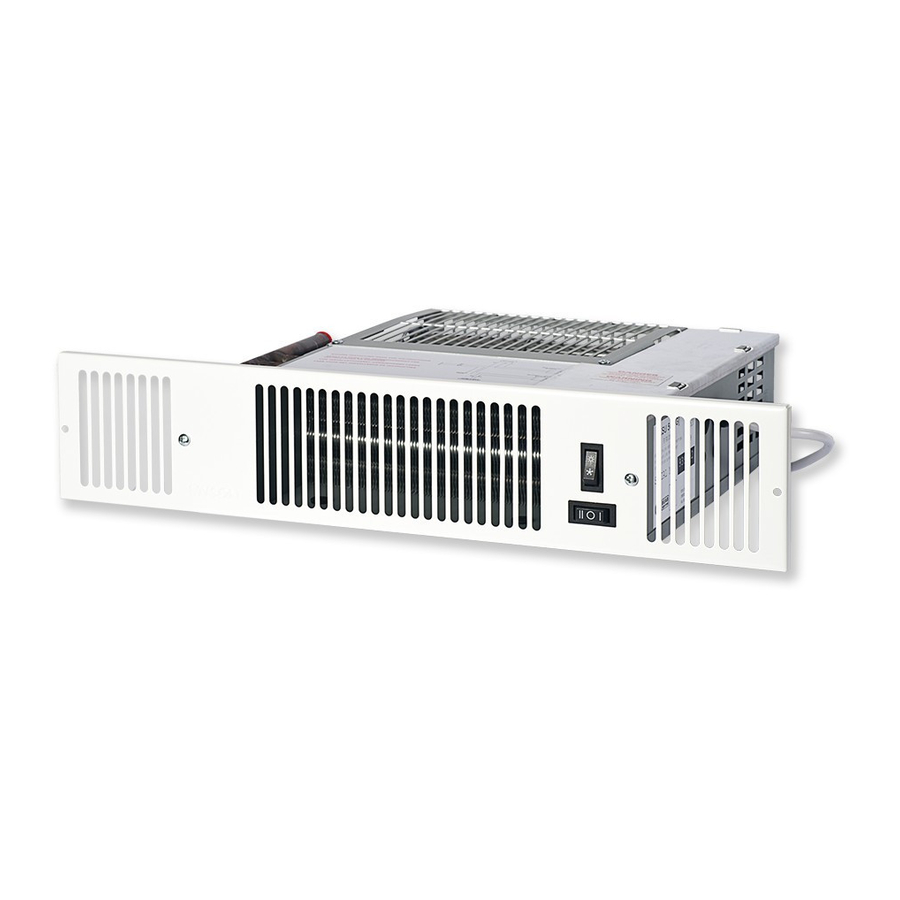
Myson KICKSPACE 500 Installation Instructions
Remote control switch.
Hide thumbs
Also See for KICKSPACE 500:
- Installation & operation manual (12 pages) ,
- Installation & operating manual (12 pages) ,
- Manual (10 pages)
Advertisement
Table of Contents
KICKSPACE
®
REMOTE CONTROL SWITCH.
SWITCH INSTALLATION INSTRUCTIONS
l
This remote control switch is suitable for operating one
KICKSPACE
®
unit only.
l
It is important that these instructions are read thoroughly
before proceeding with the installation.
l
This kit must be installed by a qualified electrician.
l
This accessory pack is designed to convert a MYSON
KICKSPACE
fan convector unit from integral switch
®
controls providing Off and two fan speeds to a remote
switching facility of the same sequence.
1.0 Controls Switch
1. Locate a convenient wall space above the KICKSPACE
convector that will permit connection via the three
metre cord supplied. The switch mounting point must be
away from sources of moisture and heat.
2. Fit a suitable switch mounting box for the type of installation.
Connect one end of the three metre cord to the remote
switch as shown in the Remote Control Unit diagram on
the back.
2.0 KICKSPACE
®
Unit
1. Remove the fixing screw(s) and lift the tabs holding the
electrical connection cover in place.
2. Locate the fan speed switch on the front control panel.
Disconnect the red and yellow wires that connect between
this switch. Discard these wires.
3. Remove the brown wire from the back of the fan speed
switch.
4. A cable clamp bush is supplied with the Remote Control
Kit. Route the cable through the hole in the side panel,
and make the following connections:
Yellow lead:
Connect to the low fan speed spade connector.
Red lead:
Connect to the high fan speed spade connector.
Brown lead:
Connect to the brown wire disconnected from the fan
speed switch.
Green/Yellow:
Connect to chassis earth tag.
500, 600 & 800
Product Serial Number:
Please leave this manual with the end user.
Part Number: 1370062
l
This pack contains a three metre length of cord specially
terminated and colour coded for the application. No other
cord can be used to connect the remote control switch to
the fan convector unit.
Important: Isolate the electricity supply to the
®
KICKSPACE
fan convector. Do not reinstate the
supply until the installation has been completed in
accordance with these instructions.
3. The cord must be installed in accordance with current
®
fan
codes of practice. It should preferably be recessed, but
if exposed, it shall be protected by suitable conduit.
Run the cord via the prepared route to the KICKSPACE
fan convector.
Fit the cable clamp bush onto the cable ensuring that
internal wiring is not too tight, and that it does not contact
the copper heat exchanger pipe-work.
5. Refit the control cover onto the unit.
6. Reinstate the electrical supply to the KICKSPACE
convector.
®
Low Terminal (Yellow)
High Terminal
(Red)
Common
Terminal
(Blue)
Motor Connections
®
fan
Advertisement
Table of Contents

Related Manuals for Myson KICKSPACE 500


Summary of Contents for Myson KICKSPACE 500
- Page 1 This kit must be installed by a qualified electrician. Important: Isolate the electricity supply to the This accessory pack is designed to convert a MYSON ® KICKSPACE fan convector. Do not reinstate the...
- Page 2 Metallic Remote Switch After Sales Service MYSON SERVICE, Unicorn Trading Park, Somerden Road, Hull, HU9 5PE, UK T: 01482 711709 Fax 01482 787221, service.convectors@myson.co.uk, www.myson.co.uk Spare parts and technical help on all Convector products are available from MYSON SERVICE. heatingthroughinnovation.
Need help?
Do you have a question about the KICKSPACE 500 and is the answer not in the manual?
Questions and answers