
Related Manuals for Huawei G700-U10


Summary of Contents for Huawei G700-U10
-
Page 1: Maintenance Manual
G700-U10 Smartphone Maintenance Manual Issue Date 2013-07-22 HUAWEI TECHNOLOGIES CO., LTD. - Page 2 Notice The purchased products, services and features are stipulated by the contract made between Huawei and the customer. All or part of the products, services and features described in this document may not be within the purchase scope or the usage scope. Unless otherwise specified in the contract, all statements, information, and recommendations in this document are provided "AS IS"...
-
Page 3: About This Document
Maintenance Manual 1About This Document About This Document Author Prepared by Date Reviewed by Date Approved by Date Change History Date Version Change Changed Description Author Reason Chapter Issue 1.0 (2013-07-22) Huawei Proprietary and Confidential Copyright © Huawei Technologies Co., Ltd. -
Page 4: Table Of Contents
6.5 Troubleshooting Upgrade Failures ..........................19 7 Maintenance Tools ........................20 8 Disassembly Procedure ......................22 9 Assembly Procedure ........................26 10 Circuit and Failure Analysis ....................29 Issue 1.0 (2013-07-22) Huawei Proprietary and Confidential Copyright © Huawei Technologies Co., Ltd. - Page 5 11 Solder Points on the PCB and BGA Chips ................91 12 Functional Tests......................... 93 12.1 Keys ..................................93 12.2 MMI Test .................................. 94 12.3 Voice Call Test ................................96 Issue 1.0 (2013-07-22) Huawei Proprietary and Confidential Copyright © Huawei Technologies Co., Ltd.
-
Page 6: Product Overview
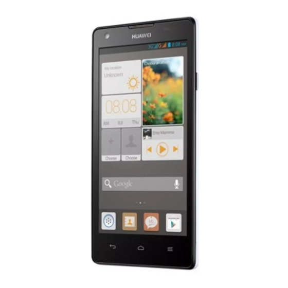
Figure 2-1 G700-U10 2.2 Product Specifications Table 2-1 G700-U10 specifications Item Description Dimensions 134 mm x 67 mm x 9.0 mm (5.28 in. x 2.64 in. x 0.35 in.) Issue 1.0 (2013-07-22) Huawei Proprietary and Confidential Copyright © Huawei Technologies Co., Ltd. - Page 7 < 108 dBm (wired); BER ≤ 0.001 (UE) Static sensitivity Operating temperature: –10° C to +45° C Temperature Storage temperature: –40° C to +70° C Humidity Operating humidity: 5% to 95% RH Issue 1.0 (2013-07-22) Huawei Proprietary and Confidential Copyright © Huawei Technologies Co., Ltd.
-
Page 8: Applicable Scope And Precautions
3.1 Applicable Scope This document provides maintenance instructions for technical support at the authorized service centers. Being Huawei proprietary, this document is accessible only for authorized service centers and companies. Although every effort was made to ensure the accuracy of this document, errors may still exist. -
Page 9: Exploded View
Maintenance Manual 4 Exploded View Exploded View Figure 4-1 G700-U10 exploded view The components listed in Table 4-1 are structural parts of the phone and cannot be used as reference when requesting spare parts. Table 4-1 Components in the exploded view... - Page 10 51634473 Front camera adhesive 03010UPG Volume key FPC 03022BEX Speaker FPC 03022ALM PCBA 03010UPH Power key FPC 22020111 Speaker 51660EGB Rear cover 27161363 Main antenna 24021243 Battery Issue 1.0 (2013-07-22) Huawei Proprietary and Confidential Copyright © Huawei Technologies Co., Ltd.
-
Page 11: Components Layout
U1302 LCD bias driver Fault symptom: LCD failure J902 USB connector Mircrophone Fault symptom: USB device detection Fault symptom: failure or charging failure microphone failure Issue 1.0 (2013-07-22) Huawei Proprietary and Confidential Copyright © Huawei Technologies Co., Ltd. - Page 12 J802 Speaker BTB failure connector Fault symptom: motor Backlight driving IC failure, speaker failure, Fault symptom: and keypad backlight backlight failure failure Main antenna connectors Fault symptom: reception failure Issue 1.0 (2013-07-22) Huawei Proprietary and Confidential Copyright © Huawei Technologies Co., Ltd.
-
Page 13: Proximity Sensor Fpc
Figure 5-3 Proximity sensor FPC 3-in-1 sensor Fault symptom: proximity sensor failure, light sensor failure, and IR sensor failure 5.3 Speaker FPC Figure 5-4 Speaker FPC Motor Fault symptom: motor failure Issue 1.0 (2013-07-22) Huawei Proprietary and Confidential Copyright © Huawei Technologies Co., Ltd. -
Page 14: Component Lists
Dedicated 14240460 J801 and J802 Connector,female,10Pin,0.4mm,0.9mm,SMT,Te rminal Dedicated 14240582 Card Socket,Battery connector,4PIN,Mid J901 Mount,Side Contact,2.50mm,With Plastic Peg,0.50mm,Terminal Dedicated 14240272 IO Connector,Micro_B-Female,5pin,Side J902 Plugging Type,SMT,Terminal Dedicated 14240181 J1001 Issue 1.0 (2013-07-22) Huawei Proprietary and Confidential Copyright © Huawei Technologies Co., Ltd. - Page 15 ZD Dedicated Inductor and Bead,EMI LB301 and Bead,330ohm@100MHZ,25%,1.5A,0.08ohm,06 LB302 03,Terminal Dedicated 10100078 Terminal EMI LB1101 Bead,1000ohm,25%,0.6A,0.35ohm,0603,1000oh m typ@1GHZ 10100184 LB1102, Terminal EMI LB1103, Bead,1800ohm,25%,0.2A,2.2ohm,0402,Termina LB1104, and l Dedicated LB1107 Issue 1.0 (2013-07-22) Huawei Proprietary and Confidential Copyright © Huawei Technologies Co., Ltd.
- Page 16 Switching Regulators,dual channel backlight U1301 driver,2.7V~6.5V,30mA*2,1.2MHz,CSP-9L,Ter minal Dedicated 39110636 Switching Regulators,0~5.5V U1302 0~-7V,1%,0.08A,ThinQFN,SMT,3mm*3mm,LC D Driver,Terminal Dedicated 43140187 Interface Controller,TP IC,2.85V,UFBGA60, U1501 Terminal Dedicated DDR2 DRAM,16Gb 40020226 U1801 LPDDR2,533MHz,32bit,1.8V/1.2V,134BALL FBGA,Terminal Dedicated Issue 1.0 (2013-07-22) Huawei Proprietary and Confidential Copyright © Huawei Technologies Co., Ltd.
- Page 17 MM,Terminal Dedicated 13080176 Duplexer,880~915MHz;925~960MHz,3.9dB.,4. U3402 7dB.,38dB.,2016,Terminal Dedicated 12020125 Crystal,0.032768MHz,12.5pF+/-30ppm,60/80ko X301 hm,3.2*1.5 SMD,Terminal Dedicate,ELOM,TS16949 Crystal 12020268 X3101 Oscillitor,26MHz,7.5pF,+/-10ppm,30ohm,3225, Terminal Dedicated 15040393 Transient Suppression Z1401 Diode,6V,25V,0.1w,3A,400um 15pin SMT,Terminal Dedicated Issue 1.0 (2013-07-22) Huawei Proprietary and Confidential Copyright © Huawei Technologies Co., Ltd.
-
Page 18: Proximity Sensor Fpc Components
D101 and D102 Diode,6V,12V,50W,5A,SOD923 15020099 LED,0.045cd,White,5mA,0603,SMD,Terminal D103, D104, and Dedicated D105 14240459 J101 Connector,male,10Pin,0.4mm,0.9mm,SMT,Ter minal Dedicated 32050032 Oscillating U101 Motor,SMT,2.7,75A,14000rpm,11mm*4.4mm* 3.6mm,Null,28ohm 15040311 D101 and D102 Transient Suppression Issue 1.0 (2013-07-22) Huawei Proprietary and Confidential Copyright © Huawei Technologies Co., Ltd. - Page 19 Diode,6V,12V,50W,5A,SOD923 These component lists are for your reference only and subject to changes without notices. The latest component lists are available in Huawei's BOM information system. If you have any questions, contact technical support in your region. Issue 1.0 (2013-07-22) Huawei Proprietary and Confidential Copyright ©...
-
Page 20: Software Upgrade
Check that the battery has sufficient power remaining to prevent an upgrade from being interrupted. Upgrading the phone will erase the user data. Back up the important data before an upgrade. Issue 1.0 (2013-07-22) Huawei Proprietary and Confidential Copyright © Huawei Technologies Co., Ltd. -
Page 21: Installing The Usb Driver
6.4 Upgrade Methods 6.4.1 Performing a USB Upgrade Use the upgrade tool HUAWEI THMTK6515ML02Ver1003 (1312) for USB upgrades. See the following attachment for guidance. The upgrade is capable of data erasing and software upgrade, eliminating the need of a dedicated data erasing tool and meeting the customer service requirements. - Page 22 Step 3 Touch SD 卡升级 then 确定. The phone automatically restarts and displays the startup logo then the upgrade screen, as shown in Figure 6-2. Figure 6-2 Upgrade screen Issue 1.0 (2013-07-22) Huawei Proprietary and Confidential Copyright © Huawei Technologies Co., Ltd.
- Page 23 R&D personnel. During a microSD upgrade, some of the upgrade information is displayed on the screen, while most information is saved in the sdload.log file. Issue 1.0 (2013-07-22) Huawei Proprietary and Confidential Copyright © Huawei Technologies Co., Ltd.
-
Page 24: Troubleshooting Upgrade Failures
Check that the upgrade file is correct. failure Check that the upgrade method is correct. Check that the microSD card functions properly. Perform the upgrade again. Issue 1.0 (2013-07-22) Huawei Proprietary and Confidential Copyright © Huawei Technologies Co., Ltd. -
Page 25: Maintenance Tools
Usage: heats components Name: heat gun Usage: heats components Name: soldering iron Usage: solders components Name: DC power supply Usage: supplies power Name: soldering fixture Usage: secures PCBAs Issue 1.0 (2013-07-22) Huawei Proprietary and Confidential Copyright © Huawei Technologies Co., Ltd. - Page 26 Name: lead-free tin solder wire Usage: solders components Name: digital multimeter Usage: measures parameters during maintenance Name: toolkit Usage: assembles and disassembles terminals Name: electric screwdriver Usage: fastens and removes screws Issue 1.0 (2013-07-22) Huawei Proprietary and Confidential Copyright © Huawei Technologies Co., Ltd.
-
Page 27: Disassembly Procedure
1. Ensure that the ESD wrist strap is properly grounded. 4. Remove the rear cover using the spudger. 3. Remove the nine screws used to secures the rear cover to the front cover. Issue 1.0 (2013-07-22) Huawei Proprietary and Confidential Copyright © Huawei Technologies Co., Ltd. - Page 28 8. Release the speaker BTB connector from the PCBA. 10. Release the PCBA from the front cover. 9. Open the ZIF socket and pull the volume key FPC out. Issue 1.0 (2013-07-22) Huawei Proprietary and Confidential Copyright © Huawei Technologies Co., Ltd.
- Page 29 13. Remove the proximity sensor FPC. 14. Release the front camera BTB connector from the PCBA. 16. Remove the front camera conductive adhesive. 15. Remove the front camera. Issue 1.0 (2013-07-22) Huawei Proprietary and Confidential Copyright © Huawei Technologies Co., Ltd.
- Page 30 G700-U10 Smartphone Maintenance Manual 8 Disassembly Procedure 17. The phone is now successfully disassembled. Issue 1.0 (2013-07-22) Huawei Proprietary and Confidential Copyright © Huawei Technologies Co., Ltd.
-
Page 31: Assembly Procedure
1. Ensure that the ESD wrist strap is properly grounded. 2. Attach the front camera conductive adhesive. 4. Fasten the front camera BTB connector to the 3. Install the front camera. PCBA. Issue 1.0 (2013-07-22) Huawei Proprietary and Confidential Copyright © Huawei Technologies Co., Ltd. - Page 32 7. Attach the proximity sensor rubber. Pay attention to properly fastened. the direction of the rubber. 9. Fasten the TP BTB connector to the PCBA. 10. Fasten the LCD BTB connector to the PCBA. Issue 1.0 (2013-07-22) Huawei Proprietary and Confidential Copyright © Huawei Technologies Co., Ltd.
- Page 33 14. Install the rear cover assembly. connector to the PCBA. 15. Tighten the nine screws. 16. Install the battery cover, and the phone is now successfully assembled. Issue 1.0 (2013-07-22) Huawei Proprietary and Confidential Copyright © Huawei Technologies Co., Ltd.
-
Page 34: Circuit And Failure Analysis
10.1 Solution Introduction Figure 10-1 Functional blocks of the G700-U10 The G700-U10 is a WCDMA bar-type phone developed by Huawei based on the MT6589, MT6320, and RF chip MT6167 of MTK. Issue 1.0 (2013-07-22) Huawei Proprietary and Confidential Copyright ©... -
Page 35: Baseband Subsystem
PCBA through springs. All the preceding components plus the covers and battery comprise a mobile phone. The G700-U10 incorporates a 5-inch TFT LCD with a resolution of 1280 x 720 pixels. The phone has a built-in RF antenna and works with a 2150 mAh Li-polymer battery. - Page 36 OVP event does not occur. However, if the voltage is lower than the UVLO voltage or the battery is not Issue 1.0 (2013-07-22) Huawei Proprietary and Confidential Copyright © Huawei Technologies Co., Ltd.
- Page 37 The power-on failures include the following types: No current startup failure Weak current startup failure Excessive current startup failure Issue 1.0 (2013-07-22) Huawei Proprietary and Confidential Copyright © Huawei Technologies Co., Ltd.
- Page 38 Replace Is the power key FPC power faulty? key FPC Is the voltage on R1502 Check between U202 3.4 V to 4.2 V? Resolder and replace U401 Issue 1.0 (2013-07-22) Huawei Proprietary and Confidential Copyright © Huawei Technologies Co., Ltd.
- Page 39 VDD18 = 1.8 V Are the VCORE, VAPROC, and Resolder or VDD18 voltages replace U202 normal? Is X700's output Resolder or frequency 26 MHz? replace X700 Resolder or replace U401 Issue 1.0 (2013-07-22) Huawei Proprietary and Confidential Copyright © Huawei Technologies Co., Ltd.
- Page 40 Reference Value or Waveform VBAT Battery voltage 3.2 V to 4.2 V VCORE Digital core voltage 1.1 V VAPROC Processor voltage 1.2 V VDD18 I/O voltage 1.8 V Issue 1.0 (2013-07-22) Huawei Proprietary and Confidential Copyright © Huawei Technologies Co., Ltd.
-
Page 41: Charging Management Circuit
The PM chip MT6329 incorporates a charging solution. Three charging modes are available, including trickle charging, constant current charging, and constant voltage charging. The charging module in the MT6329 is used to control the charging for the phone. The G700-U10 can be charged using chargers or USB cables connected to computers. - Page 42 3.3 V, constant current charging starts. The charging current in this process can be controlled by the phone software. On the charger provided with the G700-U10, the triode is completely enabled to activate the charger's automatic current limiting function. When the battery voltage reaches 4.1 V, constant voltage charging starts.
- Page 43 A charger is connected to the phone but the phone does not respond. The phone displays the charging icon on the screen but in fact the battery fails to be charged. Issue 1.0 (2013-07-22) Huawei Proprietary and Confidential Copyright © Huawei Technologies Co., Ltd.
- Page 44 Circuit Signals Table 10-2 Circuit signals of this section Signal Description Reference Value or Waveform VBUS Charging power input 4.2 V Issue 1.0 (2013-07-22) Huawei Proprietary and Confidential Copyright © Huawei Technologies Co., Ltd.
- Page 45 A 0.2 ohm resistor (R909) is added between ISENSE and VBAT to detect the charging current. The phone software controls the charging process based on the charging current. Issue 1.0 (2013-07-22) Huawei Proprietary and Confidential Copyright © Huawei Technologies Co., Ltd.
-
Page 46: Clock Circuit
G700-U10 Smartphone Maintenance Manual 10 Circuit and Failure Analysis 10.2.3 Clock Circuit Circuit Diagram Figure 10-11 Clock circuit Issue 1.0 (2013-07-22) Huawei Proprietary and Confidential Copyright © Huawei Technologies Co., Ltd. - Page 47 The clock signals output by the 32 kHz crystal pass the buffer and are then sent to the MT6320 and MT6628Q to keep the system running in sleep mode. Issue 1.0 (2013-07-22) Huawei Proprietary and Confidential Copyright © Huawei Technologies Co., Ltd.
- Page 48 26 MH temperature Provides clock signals for the compensation crystal GPS module in the MT6628Q oscillator 32 kHz crystal Provides clock signals for the MT6230 and then the MT6628Q Issue 1.0 (2013-07-22) Huawei Proprietary and Confidential Copyright © Huawei Technologies Co., Ltd.
-
Page 49: Memory Circuit
G700-U10 Smartphone Maintenance Manual 10 Circuit and Failure Analysis 10.2.4 Memory Circuit Circuit Diagram Figure 10-14 Memory circuit Issue 1.0 (2013-07-22) Huawei Proprietary and Confidential Copyright © Huawei Technologies Co., Ltd. -
Page 50: Rf Subsystem
BAND 8 PA, and 4-in-1 chip MT6628Q that includes the Wi-Fi, Bluetooth, GPS, and FM modules. They are described in detail as follows: The G700-U10 is a WCDMA smartphone based on the MTK platform MT6589+MT6167. The MT6589's quad-core processor is the newest generation ARM Cortex-A7 core processor, and its main frequency is 1.2 GHz. -
Page 51: Receive Channel
G700-U10 Smartphone Maintenance Manual 10 Circuit and Failure Analysis Figure 10-15 Platform structure 10.3.2 Receive Channel Circuit Diagram Figure 10-16 GSM PA and RF switch Issue 1.0 (2013-07-22) Huawei Proprietary and Confidential Copyright © Huawei Technologies Co., Ltd. - Page 52 G700-U10 Smartphone Maintenance Manual 10 Circuit and Failure Analysis Figure 10-17 Receive channel of the GSM 900 MHz and BAND 8 Figure 10-18 Receive channel of BAND1 Issue 1.0 (2013-07-22) Huawei Proprietary and Confidential Copyright © Huawei Technologies Co., Ltd.
- Page 53 G700-U10 Smartphone Maintenance Manual 10 Circuit and Failure Analysis Figure 10-19 Receive channels of the GSM 1800 MHz and 1900 MHz Issue 1.0 (2013-07-22) Huawei Proprietary and Confidential Copyright © Huawei Technologies Co., Ltd.
- Page 54 Is any component on the faulty circuit poorly soldered? Is there any missing component on the receive channel of each band? Return the phone to Huawei for repair Issue 1.0 (2013-07-22) Huawei Proprietary and Confidential Copyright © Huawei Technologies Co., Ltd.
-
Page 55: Transmit Channel
G700-U10 Smartphone Maintenance Manual 10 Circuit and Failure Analysis 10.3.3 Transmit Channel Circuit Diagram Figure 10-21 GSM transmit channel Figure 10-22 BAND1 transmit channel Issue 1.0 (2013-07-22) Huawei Proprietary and Confidential Copyright © Huawei Technologies Co., Ltd. - Page 56 Is there any missing component on the circuit of each band? Return the phone to Huawei for repair Issue 1.0 (2013-07-22) Huawei Proprietary and Confidential Copyright © Huawei Technologies Co., Ltd.
-
Page 57: Gps Channel
If yes, check whether the LNA back end has signals (the GPS module has no RF switch, use an RF cable for the inspection). If not, replace the LNA. If the circuit has no missing component but the problem persists, return the phone to Huawei for repair. - Page 58 If no component is missing on the Wi-Fi circuit, the 4-in-1 chip may be damaged. Return the phone to Huawei for repair. Issue 1.0 (2013-07-22) Huawei Proprietary and Confidential Copyright © Huawei Technologies Co., Ltd.
-
Page 59: Peripheral Circuits
G700-U10 Smartphone Maintenance Manual 10 Circuit and Failure Analysis 10.4 Peripheral Circuits 10.4.1 LCD Circuit Circuit Diagram Figure 10-27 LCD circuit Issue 1.0 (2013-07-22) Huawei Proprietary and Confidential Copyright © Huawei Technologies Co., Ltd. - Page 60 Resolder or replace U401 T1303 disconnected or short- circuited? Is the LCD backlight (VLED_P and VLED_N) normal? Are the Resolder or replace U1301 surrounding components disconnected or short-circuited? Replace J1301 Issue 1.0 (2013-07-22) Huawei Proprietary and Confidential Copyright © Huawei Technologies Co., Ltd.
- Page 61 DC voltage: about 25 V VLED_K1 Backlight adjusting signal VLED_K2 Backlight adjusting signal LCD_CABC Backlight adjusting signal Switch on: high level or PWM signal Switch off: 0 V Ground cable Issue 1.0 (2013-07-22) Huawei Proprietary and Confidential Copyright © Huawei Technologies Co., Ltd.
-
Page 62: Tp Circuit
G700-U10 Smartphone Maintenance Manual 10 Circuit and Failure Analysis 10.4.2 TP Circuit Circuit Diagram Figure 10-29 TP circuit Issue 1.0 (2013-07-22) Huawei Proprietary and Confidential Copyright © Huawei Technologies Co., Ltd. - Page 63 Table 10-6 Circuit signals of this section Signal Description Reference Value or Waveform VDD_CTP TP controller power supply 2.85 V VDD18_PMU TP controller power supply 1.8 V Issue 1.0 (2013-07-22) Huawei Proprietary and Confidential Copyright © Huawei Technologies Co., Ltd.
-
Page 64: Front Camera Circuit
The front camera supports a resolution of 1.3 mega pixels, uses a 24-pin BTB connector and parallel interface to communicate with the PCBA, and is controlled through the I2C data bus. Issue 1.0 (2013-07-22) Huawei Proprietary and Confidential Copyright © Huawei Technologies Co., Ltd. - Page 65 MIPI differential clock Camera I2C signal for transmitting SCL1 Digital pulse signal control and configuration data SDA1 Digital pulse signal SUBCAM_D0N/P MIPI differential data signal Differential data signal Issue 1.0 (2013-07-22) Huawei Proprietary and Confidential Copyright © Huawei Technologies Co., Ltd.
-
Page 66: Rear Camera Circuit
The rear camera supports a resolution of 8 mega pixels, uses a 24-pin BTB connector and MIPI interface to communicate with the PCBA, and is controlled through the I2C data bus. Issue 1.0 (2013-07-22) Huawei Proprietary and Confidential Copyright © Huawei Technologies Co., Ltd. - Page 67 High-speed digital pulse signal MIPI_CLKN MIPI clock signal High-speed digital pulse signal High-speed digital pulse MIPI_DATAP0 MIPI data signal signal MIPI_DATAN0 MIPI data signal High-speed digital pulse signal Issue 1.0 (2013-07-22) Huawei Proprietary and Confidential Copyright © Huawei Technologies Co., Ltd.
-
Page 68: G-Sensor Circuit
Effective when at low level The operating level is high. PWDN_VCM Autofocus enabling signal Default: low level Operating: high level 10.4.5 G-Sensor Circuit Circuit Diagram Figure 10-35 G-sensor circuit Issue 1.0 (2013-07-22) Huawei Proprietary and Confidential Copyright © Huawei Technologies Co., Ltd. - Page 69 When no signal is transferring, the level is high. SCL0 I2C signal, used to read the High and low pulses acceleration information SDA0 High and low pulses Issue 1.0 (2013-07-22) Huawei Proprietary and Confidential Copyright © Huawei Technologies Co., Ltd.
-
Page 70: 3-In-1 Sensor Circuit
Figure 10-38 Troubleshooting light sensor failures Light sensor failure VDD28_PMU Check U202 normal? Is the light sensor Resolder or replace U101 chip normal? Resolder or replace U401 Issue 1.0 (2013-07-22) Huawei Proprietary and Confidential Copyright © Huawei Technologies Co., Ltd. -
Page 71: Key Circuit
I2C signal, used to read the light, High and low pulses proximity, and IR sensing information SDA0 High and low pulses 10.4.7 Key Circuit Circuit Diagram Figure 10-39 Key circuit Issue 1.0 (2013-07-22) Huawei Proprietary and Confidential Copyright © Huawei Technologies Co., Ltd. - Page 72 The key circuit is simple because only three keys (power, volume up, and volume down) are used on the G700-U10. Each key is controlled by a signal. When a key is not pressed, its control signal is at high level; when it is pressed, the control circuit is short-circuited to the ground, and the control signal changes to low level.
-
Page 73: Motor Circuit
Troubleshooting Process Figure 10-42 Troubleshooting motor failures Motor failure Is the motor Resolder the motor properly soldered? Is the motor Replace the motor normal? Resolder or replace U202 Issue 1.0 (2013-07-22) Huawei Proprietary and Confidential Copyright © Huawei Technologies Co., Ltd. -
Page 74: Receiver Circuit
PCBA through springs. C1123 and C1124 filter the RF interference out, and C1125 filters the differential interference out. D1103 and D1104 are the ESD components. Issue 1.0 (2013-07-22) Huawei Proprietary and Confidential Copyright © Huawei Technologies Co., Ltd. - Page 75 Table 10-13 Circuit signals of this section Signal Description Reference Value or Waveform Differential input's negative Analog differential signal electrode Differential input's positive Analog differential signal electrode Issue 1.0 (2013-07-22) Huawei Proprietary and Confidential Copyright © Huawei Technologies Co., Ltd.
-
Page 76: Microphone Circuit
CPU for processing. C1120 and C1121 block the DC voltage. R1106 is the bias resistor. C1110 and C1111 filter the RF interference out. Issue 1.0 (2013-07-22) Huawei Proprietary and Confidential Copyright © Huawei Technologies Co., Ltd. - Page 77 Reference Value or Waveform VMIC Microphone power supply 1.9 V MICP0 Differential signal input's positive electrode Analog differential signal MICN0 Differential signal input's negative electrode Analog differential signal Issue 1.0 (2013-07-22) Huawei Proprietary and Confidential Copyright © Huawei Technologies Co., Ltd.
-
Page 78: Speaker Circuit
The speaker is driven by the SPK_P and SPK_N differential signals output by the MT6320. The speaker connects to the speaker FPC through springs. C101 and C102 filter the RF interference out. The speaker applies foolproof design. Issue 1.0 (2013-07-22) Huawei Proprietary and Confidential Copyright © Huawei Technologies Co., Ltd. - Page 79 Circuit Signals Table 10-15 Circuit signals of this section Signal Description Reference Value or Waveform SPK_P Differential signal input PWM signal SPK_N Differential signal input PWM signal Issue 1.0 (2013-07-22) Huawei Proprietary and Confidential Copyright © Huawei Technologies Co., Ltd.
-
Page 80: Headset Circuit
When EARBIAS is at high level, the MT6589 detects the ACCDET pin. If the pin is detected as low, the chip determines that the key has been pressed. Issue 1.0 (2013-07-22) Huawei Proprietary and Confidential Copyright © Huawei Technologies Co., Ltd. - Page 81 J1101 Identify the Is the EARBIAS cause and voltage normal? fix it Is the microphone circuit Clear faults short-circuited to the on the circuit ground? Replace U401 Issue 1.0 (2013-07-22) Huawei Proprietary and Confidential Copyright © Huawei Technologies Co., Ltd.
- Page 82 Pulse signal HPRP Headset left channel Pulse signal MICN1 Negative electrode of the microphone Differential signal differential signal Negative electrode of the microphone MICP1 Differential signal differential signal Issue 1.0 (2013-07-22) Huawei Proprietary and Confidential Copyright © Huawei Technologies Co., Ltd.
-
Page 83: Sim Card Circuit
Figure 10-52 SIM card circuit Circuit Analysis The G700-U10 supports two SIM cards. Figure 10-53 shows the SIM card circuit, which is a common one that can be seen on basically every platform. SCLK is the clock signal, SRST is the reset signal, VSIM_PMU is the power supply signal, and SIO is the data signal. - Page 84 Reference Value or Waveform SCLK Clock signal SRST Reset signal VSIM_PMU Voltage signal If the card can be detected, the voltage should be 3.3 V. Data signal Issue 1.0 (2013-07-22) Huawei Proprietary and Confidential Copyright © Huawei Technologies Co., Ltd.
-
Page 85: Microsd Card Circuit
The microSD card holder is on the PCB and communicates with U401 through Z1401. Data transmission (read and write) to the microSD card complies with the standard microSD card protocol. Issue 1.0 (2013-07-22) Huawei Proprietary and Confidential Copyright © Huawei Technologies Co., Ltd. - Page 86 MC1CM0 Command signal MC1DA0—MC1DA3 Data signal SD-DET microSD detection signal SD-DET is at high level when the microSD is in position. Otherwise, it is at low level. Issue 1.0 (2013-07-22) Huawei Proprietary and Confidential Copyright © Huawei Technologies Co., Ltd.
-
Page 87: Usb Port Circuit
The USB port circuit is simple. USB_DM and USB_DP are the data lines. VUSB is the voltage signal, which is 3.3 V. KCOL0 is the USB download triggering signal. When KCOL0 is grounded, the system enters USB download mode. Issue 1.0 (2013-07-22) Huawei Proprietary and Confidential Copyright © Huawei Technologies Co., Ltd. - Page 88 High-speed digital pulse signal USB_DP USB data (–) High-speed digital pulse signal KCOL0 USB download triggering When KCOL0 is grounded, the system enters signal USB download mode. Issue 1.0 (2013-07-22) Huawei Proprietary and Confidential Copyright © Huawei Technologies Co., Ltd.
-
Page 89: Wi-Fi Module Circuit
G700-U10 Smartphone Maintenance Manual 10 Circuit and Failure Analysis 10.4.16 Wi-Fi Module Circuit Circuit Diagram Figure 10-58 Wi-Fi module circuit Issue 1.0 (2013-07-22) Huawei Proprietary and Confidential Copyright © Huawei Technologies Co., Ltd. - Page 90 The external power supply provides the VBAT and 2.8 V voltages to the MT6628Q. The LDO inside the MT6628Q provides a 1.7 V voltage for the on-chip modules. Figure 10-59 MT6628Q structure Issue 1.0 (2013-07-22) Huawei Proprietary and Confidential Copyright © Huawei Technologies Co., Ltd.
-
Page 91: Bluetooth Module Circuit
The Bluetooth antenna connects to the antenna on the phone housing through the spring J2301. The Wi-Fi module and Bluetooth module share the antenna. Issue 1.0 (2013-07-22) Huawei Proprietary and Confidential Copyright © Huawei Technologies Co., Ltd. -
Page 92: Gps Module Circuit
UART interface used for BT&GPS&FM control signal BGF_INT_B_6628 BT&GPS&FM interrupt signal 10.4.18 GPS Module Circuit Circuit Diagram See section 10.4.16 "Wi-Fi Module Circuit" for the module's circuit diagram. Issue 1.0 (2013-07-22) Huawei Proprietary and Confidential Copyright © Huawei Technologies Co., Ltd. -
Page 93: Fm Module Circuit
UART interface used for BT&GPS&FM control signal 10.4.19 FM Module Circuit Circuit Diagram See section 10.4.16 "Wi-Fi Module Circuit" for the module's circuit diagram. Figure 10-63 shows the FM antenna circuit. Issue 1.0 (2013-07-22) Huawei Proprietary and Confidential Copyright © Huawei Technologies Co., Ltd. - Page 94 Resolder or replace the Is the headset jack headset jack and check properly soldered? the surrounding components Is the 4-in-1 chip Resolder U2200 U2200 properly soldered? Resolder or replace U401 Issue 1.0 (2013-07-22) Huawei Proprietary and Confidential Copyright © Huawei Technologies Co., Ltd.
- Page 95 FM audio left channel signal FM_IN_R FM audio right channel signal I2S_DATA_IN_6628 FM I2S data signal I2S_CLK_6628 FM I2S clock signal I2S_WS_6628 FM I2S world select signal Issue 1.0 (2013-07-22) Huawei Proprietary and Confidential Copyright © Huawei Technologies Co., Ltd.
-
Page 96: Solder Points On The Pcb And Bga Chips
: vacant point; Green (R: 0, G: 255, B: 0) : ground point; Blue (R: 0, G: 0, B: 255) : solder point Figure 11-1 Solder points on PCB side A Issue 1.0 (2013-07-22) Huawei Proprietary and Confidential Copyright © Huawei Technologies Co., Ltd. - Page 97 G700-U10 Smartphone Maintenance Manual 11 Solder Points on the PCB and BGA Chips Figure 11-2 Solder points on PCB side B Issue 1.0 (2013-07-22) Huawei Proprietary and Confidential Copyright © Huawei Technologies Co., Ltd.
-
Page 98: Functional Tests
G700-U10 Smartphone Maintenance Manual 12 Functional Tests Functional Tests 12.1 Keys Figure 12-1 G700-U10 keys Power key Volume up Volume down Menu Return Home Issue 1.0 (2013-07-22) Huawei Proprietary and Confidential Copyright © Huawei Technologies Co., Ltd. -
Page 99: Mmi Test
If the test item passes, the phone automatically proceeds to the next test item. If the phone fails to detect the Issue 1.0 (2013-07-22) Huawei Proprietary and Confidential Copyright © Huawei Technologies Co., Ltd. - Page 100 Bluetooth devices in range and displays the devices that have been found. Press the volume down key to proceed. Prepare a device with Bluetooth enabled for this test item. Issue 1.0 (2013-07-22) Huawei Proprietary and Confidential Copyright © Huawei Technologies Co., Ltd.
-
Page 101: Voice Call Test
Step 5 If no problems are found, end the test. If any problems are found, troubleshoot the phone or send it to an advanced service center for repair. ----End Issue 1.0 (2013-07-22) Huawei Proprietary and Confidential Copyright © Huawei Technologies Co., Ltd.