
Related Manuals for MYiR MYD-Y6ULX


Summary of Contents for MYiR MYD-Y6ULX
- Page 1 MYD-Y6ULX Product Manual MYD-Y6ULX Product Manual Version 1.0 08-Nov-2017 www.myirtech.com...
- Page 2 MYD-Y6ULX Product Manual Version History Version Description DATE V1.0 Initial version 08-Nov-2017 www.myirtech.com...
-
Page 3: Table Of Contents
MYD-Y6ULX Product Manual Table of Contents Table of Contents ......................3 1.Product Abstract ......................4 2. Hardware Characteristics ..................... 8 2.1 CPU Module Resource ....................8 2.2 Base Board Resources ....................9 3. Interfaces ........................11 3.1 Interface of CPU Module Board..................11 3.2 PIN List .......................... -
Page 4: Product Abstract
MYD-Y6ULX Product Manual 1.Product Abstract The MYD-Y6ULX Development Board is a complete evaluation platform for NXP’s i.MX 6UL/6ULL processor which features the most efficient ARM Cortex-A7 core. Each processor in this family provides various memory interfaces, including 16-bit LPDDR2, DDR3, DDR3L, raw and managed NAND flash, NOR flash, eMMC, Quad SPI and a wide range of other interfaces for connecting peripherals. - Page 5 14mm, 0.8 mm ball pitch, 289 MAPBGA package on the MYC-Y6ULX. The i.MX6ULL\6UL application processor on the MYC-Y6ULX board provides multiple compatible options of Y0, Y1, Y2, G0, G1, G2 and G3 sub families.MYIR provides the following three part number by default.
- Page 6 MYD-Y6ULX Product Manual OTG, HS/FS x 1 OTG, HS/FS x 2 OTG, HS/FS x 2 OTG, HS/FS x 2 TRNG, Crypto Engine (AES TRNG, Crypto TRNG, Crypto with DPA/TDES/SHA/RSA), Engine Engine Secure Boot, tamper Security Basic (AES/TDES/SHA), (AES/TDES/SHA), monitor, Secure Boot Secure Boot PCI4.0 pre-certification,...
- Page 7 MYD-Y6ULX Product Manual 16-bit LP-DDR2, 16-bit LP-DDR2, 16-bit LP-DDR2, DRAM DDR3/DDR3L DDR3/DDR4L DDR3/DDR5L eFuse 256-bit 256-bit 256-bit NAND (BCH40) Ethernet 10/100-Mbit/s x 1 10/100-Mbit/s x 1 10/100-Mbit/s x 2 OTG, HS/FS x 1 OTG, HS/FS x 2 OTG, HS/FS x 2...
-
Page 8: Hardware Characteristics
MYD-Y6ULX Product Manual 2. Hardware Characteristics CPU Module Resource MYC-Y6ULX CPU module is compatible with i.MX 6UL and i.MX 6ULL series processors. The board with high-speed circuit board design, which is integrated processor, DDR, NAND Flash, eMMC, Ethernet PHY and power management circuit on the PCB size of 37 x 39 mm. -
Page 9: Base Board Resources
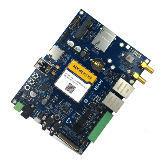
2.2 Base Board Resources The MYB-Y6ULX base board offers rich peripherals to evaluate and make developments on MYC-Y6ULX. Please refer to the below Figure 2.2 for detail. Figure 2.2 MYD-Y6ULX Base Board Serial ports - 1 x Debug serial port (TTL) - Page 10 MYD-Y6ULX Product Manual 1x CAN interface (with isolation) 1 x Micro SD card slot 1 x LCD interface (16-bit true color, supports optional 4.3-inch and 7-inch TFT LCD) 1 x RTC battery holder Audio input/output port (3.5mm jack) ...
-
Page 11: Interfaces
MYD-Y6ULX Product Manual 3. Interfaces 3.1 Interface of CPU Module Board The MYC-Y6ULX CPU module is connected to the base board by 1.0mm pitch 140-pin surface mount pads. Please refer to the pin assignment as below. Figure 3.1 MYC-Y6ULX Pin Assignment 3.2 PIN List... -
Page 12: Peripheral Interfaces Of Base Board
Rich peripheral interface resources are provided on the MYB-Y6ULX base board, which offer a comprehensive evaluating and developing platform for the MYC-Y6ULX CPU module and the i.MX6UL\6ULL series processor. Detailed resources provided as below. Figure 3.2 MYD-Y6ULX Resources Please refer to the interface list as below. Interface... - Page 13 User LED 4G Module Mini PCI-E USB LTE module interface SIM Card SIM Card interface 4G Antenna SMA LTE antenna interface WiFi Antenna SMA WiFi antenna interface Expansion Header Expansion IO header,2.0mm pitch Figure 3.1 List of MYD-Y6ULX Resources www.myirtech.com...
-
Page 14: Hardware Design
MYD-Y6ULX Product Manual 4. Hardware Design 4.1 Hardware Design of CPU Module board Please refer to the document MYC-Y6ULX Product Manual for detail information. 4.2 Hardware Design of Baseboard 4.2.1 Power supply MYB-Y6ULX base board is designed to be powered by DC 12V, and the internal power management circuit on-board supplies 5V, 3.8V, 3.3V, 1.8V, 3V (RTC) voltage for the... - Page 15 ROM code uses the state of the internal register BOOT_MODE[1:0] as well as the state of various eFUSEs and/or GPIO settings to determine the boot flow behavior of the device. MYD-Y6ULX is equipped with a 4 bit switch to change the boot device. Please refer to the schematic for the boot state as below, Figure 4.2 Boot Configure Switch...
- Page 16 MYD-Y6ULX Product Manual Switch BIT1 BIT2 SD Card eMMC Table 4.2 eMMC Version Boot Configure Bit3 and Bit4 are used to select boot type, please refer the setting as below, Switch Boot TYPE BIT4 BIT3 Boot From Fuses Serial Downloader...
- Page 17 MYD-Y6ULX Product Manual Figure 4.3 Ethernet 1 Circuit For the Ethernet 2, an additional PHY chips has to add on the base board. Please refer to the SCH of the Ethernet 2 of base board as below. Figure 4.4 Ethernet 2 Circuit 4.2.4 USB...
- Page 18 MYD-Y6ULX Product Manual controller. Two of the expanded USB host controller is connected to a dual USB connector (Type A) and Port 3 of the expanded USB has been connected to the LTE module.the rest is reserved. Please refer to the schematic of the USB OTG of the board as below. We implement a power switch circuit on the board, and the power can be automatically switched according to the access device.
- Page 19 4.2.5 LTE Module MYB-Y6ULX is equipped with a LTE module interface, which can support many general mini PCI-E LTE module. MYD-Y6ULX development board provides Linux driver support and code examples based on EC20 LTE module from quectel. The part number of the...
-
Page 20: Audio Codec
MYD-Y6ULX Product Manual mini PCIE connector is AAA-PCI-047 from LOTES. Refer to the schematic of LTE module interface as below. Figure 4.8 LTE Module Using the LTE module, the user also needs a SIM card. MYB-Y6ULX is equipped with a side insert type SIM card connector. - Page 21 MYD-Y6ULX Product Manual is connected to I2C2. Please refer to the schematic below for detail. Figure 4.10 Audio CODEC and Interface 4.2.7 WiFi MYB-Y6ULX is equipped with a SDIO WIFI module with offering SMA antenna connector. The part number of WIFI chip is WM-N-BM-02 from USI. The WiFi module support 802.11b/g/n.
-
Page 22: Camera Interface
MYD-Y6ULX Product Manual Figure 4.11 WiFi 4.2.8 Camera Interface MYB-Y6ULX is equipped with a parallel camera interface. Although the processor supports up to 24bit parallel camera interface, because of the chip pin multiplexing. MYB-Y6ULX can only support 8bit parallel camera interface. The connector is a 0.5mm pitch FPC connector. - Page 23 MYD-Y6ULX Product Manual Note: The camera signals CSI_DATA4, CSI_DATA5, CSI_DATA6, CSI_DATA7, I2C2_SDA and I2C2_SCL is reuse with the expansion interface. 4.2.9 LCD The i.MX6ULL\6UL processor provides one parallel display port, support max 85 MHz display clock and up to WXGA (1366 x 768) at 60 Hz. A 50 pins FPC connector has been used for the display port on the MYB-Y6ULX.Linux drivers are provided to work with MIYR...
- Page 24 The 3 pins header with 2.54mm pitch and 3.3V V LVTTL level standard is used on the MYB-Y6ULX. Users can use USB to UART cable to connect the board and computer. MYIR provides an optional module MY-UART012U, for more information, please visit the following Web site.
- Page 25 MYD-Y6ULX Product Manual Figure 4.15 RS232 Port MYB-Y6ULX is equipped with an RS485 interface with electrical isolation. This function is connected to the UART4 controller on the processor. Sending or receiving is controlled by a GPIO. The UART controller supports 7 bit or 8 bit data bits, 1 or 2 stop bits, and programmable parity.
- Page 26 MYD-Y6ULX Product Manual specification, supports standard and extended message frames. One CAN port is offered on MYB-Y6ULX due to the PIN reuse. MYB-Y6ULX is equipped with a CAN transceiver with electrical isolation. The part number of the transceiver is ISO1050 from TI. For more details about the ISO1050 chip, please see its datasheet.
- Page 27 MYD-Y6ULX Product Manual 4.2.13 Micro SD Card The i.MX6UL\6ULL processor provides two MMC/SD/SDIO card ports. Port SD2 has been connected to the eMMC and WiFi module, and port SD1 is connected to a micro SD card connector (4 bit mode) on the MYB-Y6ULX. It can be used to store the system booting code and other information using a mciro SD card memory.
- Page 28 MYD-Y6ULX Product Manual Figure 4.21 Buttons One user LED is equipped on the MYB-Y6ULX. Please refer to the schematic of the LED as below. Figure 4.22 LED 4.2.15 Expansion Interfaces One 20 pins Pin-Header is equipped on board.Signals such as SPI, Serial Ports,I2C are expanded through this connector.
- Page 29 MYD-Y6ULX Product Manual Figure 4.23 Expansion Interface www.myirtech.com...
-
Page 30: Electronic Characteristics
MYD-Y6ULX Product Manual 5. Electronic Characteristics 5.1 Operating temperature Parameter Des. Application Scenarios Nor. Unit — ℃ — Commercial Level WIFI chip operating — ℃ Industrial Level temperature of -20 to 65 degrees. Table 5-1 Operating Temperate 5.2 Power Supply... -
Page 31: Gpio Dc Characteristics
MYD-Y6ULX Product Manual 5.3 GPIO DC Characteristics Parameter Item Label Description Normal Unit Input High Voltage Input Low Voltage 0.99 Output high Voltage 3.15 Output Low Voltage 0.15 Table 5-3 GPIO DC Characteristics www.myirtech.com... -
Page 32: Mechanical Characteristics
MYD-Y6ULX Product Manual 6. Mechanical Characteristics PCB Layers CPU Module 8 Layers PCB, Immersion Gold Process, Lead-Free Base Board 4 Layers PCB, Immersion Gold Process, Lead-Free Mechanical CPU Module: 37 x 39mm Base Board: 105*140mm Figure 6.1 Mechanical Information of MYC-Y6ULX... - Page 33 MYD-Y6ULX Product Manual Figure 6.2 Mechanical Information of MYB-Y6ULX www.myirtech.com...
- Page 34 Delivery Time MYIR will always keep a certain stock for its regular products. If your order quantity is less than the amount of inventory, the delivery time would be within three days; if your order quantity is greater than the number of inventory, the delivery time would be always four to six weeks.
- Page 35 Product Manual Technical Support MYIR has a professional technical support team. Customer can contact us by email (support@myirtech.com), we will try to reply you within 48 hours. For mass production and customized products, we will specify person to follow the case and ensure the smooth production.
- Page 36 6) For any maintenance service, customers should communicate with MYIR to confirm the issue first. MYIR’s support team will judge the failure to see if the goods need to be returned for repair service, we will issue you RMA number for return maintenance service after confirmation.
- Page 37 During the warranty period, the shipping cost which delivered to MYIR should be responsible by user; MYIR will pay for the return shipping cost to users when the product is repaired. If the warranty period is expired, all the shipping cost will be responsible by users.
Need help?
Do you have a question about the MYD-Y6ULX and is the answer not in the manual?
Questions and answers