Advertisement
Quick Links
Australia & New Zealand
Hayward Pool Products (Australia) Pty Ltd.
Melbourne-Sydney-Brisbane-Perth
Email: sales@hayward-pool.com.au Website: www.hayward-pool.com.au
P.O Box 4384, Dandenong South, Vic. 3164
ABN 66 083 413 414
Sales Ph 1300POOLS1 Fx 1300POOLS2
30-LITINSH002 REV-A
Advertisement

Related Manuals for Hayward ENP2M-9A


Summary of Contents for Hayward ENP2M-9A
- Page 1 Australia & New Zealand Hayward Pool Products (Australia) Pty Ltd. Melbourne-Sydney-Brisbane-Perth Email: sales@hayward-pool.com.au Website: www.hayward-pool.com.au P.O Box 4384, Dandenong South, Vic. 3164 ABN 66 083 413 414 Sales Ph 1300POOLS1 Fx 1300POOLS2 30-LITINSH002 REV-A...
- Page 2 Timer...
- Page 3 and in accordance with AS/NZS 3000 Wiring Rules. AS/NZS 3000 Wiring Rules.
- Page 5 Heating mode If the temperature or humidity are outside of the ranges speci ed above, the built in protection features could activate and shutdown the swimming pool heat pump.
- Page 6 ENP2M-9A ENP3M-13A / ENP6M-21A...
- Page 8 and fastening with appropriate fasteners (bolts, screws, ect). Fasteners and washers not supplied. The unit shall not be located any closer to the swimming pool than inside zone 2 as explained in AS/NZS 3000 Wiring Rules. The unit is supplied with two 48.3 mm Ø union connections to suit 40mm PVC pipe. Connect the water inlet to the heat pump coming from the filtration group, then connect the water outlet of the heat pump to the pipe going to the pool (see diagram below).
- Page 9 AS/NZS 3000 Wiring Rules. -13A -21A circulation pump via the Heat Priority Wiring on on page 21. Potential free Dry Ccontact 230V 7 Amps maximum Never connect a circulation pump directly to terminals 1 & 2.
- Page 10 Device (RCD), with a rated residual operating current not exceeding 30mA. -Models with hard wired power input circuits must be supplied through an isolation switch in accordance with AS/NZS 3000 Wiring Rules. MODELS ENP2M-9A ENP3M-13A ENP6M-21A Always isolate the power supply to the unit before opening the electrical control box.
- Page 12 temperature change. temperature change.
- Page 17 It is recommended to never surpass a water temperature of 30°C in vinyl lined pools to avoid warpage of the liner. to see or When on or off, it is suffice to press the button modify the set point.
- Page 18 Before any maintenance operation, the heat pump must be isolated from any electrical supply(s). The maintenance operations must only be carried out by personnel that are qualified and authorised to handle liquid refrigerants. Isolate the power supply to the heat pump.
- Page 19 1.Connection of PCB illustration OUT1 OUT2 CN19 AI06 OUT3 AI05 OUT4 PC1001 AI04 OUT5 AI03 AC-N AI02 AI01 CN16 Connections explanation: Symbol Meaning OUT1 Compressor of system1(220-230VAC) Water pump control - Dry contact 230V 7A max OUT2 OUT3 4way valve (220-230VAC) OUT4 High speed of fan motor(220-230VAC)...
- Page 20 ENP2M-9A COMP RED BLU AI06 OUT3 OUT1 OUT2 BRN BLU Y/G AI05 Dry contact OUT4 7A max AI04 To power supply 220-240V~/50Hz OUT5 AI03 AT:Ambient temperature AI02 AC-N COMP:Compressor CT:Coil temperature AI01 EEV:Electronic expand valve ET:Exhaust temperature FM:Fan motor FS:Flow switch HP:High pressure protection...
- Page 21 ENP3M-13A COMP RED BLU AI06 OUT3 OUT1 OUT2 AI05 OUT4 AI04 To power supply Dry contact OUT5 AI03 220-240V~/50Hz 7A max AT:Ambient temperature AI02 COMP:Compressor AC-N CT:Coil temperature EEV:Electronic expand valve AI01 ET:Exhaust temperature FM:Fan motor FS:Flow switch HP:High pressure protection IT:Inlet water temperature LP:Low pressure protection KM1:Contacter of compressor...
- Page 22 ENP6M-21A...
- Page 23 Potential free Dry Contact 230V 7 Amps maximum Single phase pump The Heat Priority Control copmonents are to be installed by a qualified electrical contractor in accordance with AS/NZS 3000 Wiring rules. Wire terminals 1 & 2 to the timer as shown in the above diagram.
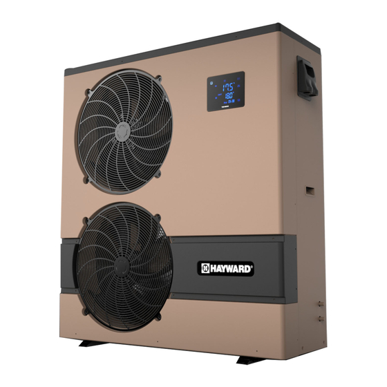
- Page 24 ENP2M-9A...
- Page 25 ENP2M-9A Item # Part Number Description HWX200022188 Protection cover HWX320822002 Front panel HWX35002701 Fan blade assy HWX34043301 Fan motor HWX320821069 Protection panel HWX321221108 Fan motor bracket HWX321221077 Support panel HWX321221079 Electrical box cover HWX320821072 Left panel HWX20041437 4 way valve Compressor capacitor 60 µF...
- Page 26 ENP3M-13A...
- Page 27 ENP3M-13A Item # Part Number Description HWX200022169 Protection cover HWX35002701 Fan blade assy HWX340433134 Fan motor HWX320822015 Front panel HWX320921025 Support panel HWX320921236 Fan motor bracket HWX320921024 Electrical box cover Transformer 230V~ 12V HWX200037003 HWX320921090 Back panel HWX2000140346 Electrical expansion valve Fan motor capacitor 5 µF HWX20003509 HWX20003909...
- Page 28 ENP6M-21A...
- Page 29 ENP6M-21A Item # Part Number Description HWX320921235 Chassis HWX320921236 Fan motor bracket HWX200021089 Protection cover HWX35002704 Fan blade assy HWX320922015 Front panel HWX200033134 Fan motor HWX320921024 Electrical box cover HWX320921025 Support panel Compressor capacitor 35 µF HWX20003504 HWX320921090 Back panel Compressor capacitor 161-193µF HWX20003511 Fan motor capacitor 5 µF...
- Page 31 • • • •...
- Page 32 • • • • •...
Need help?
Do you have a question about the ENP2M-9A and is the answer not in the manual?
Questions and answers