Table of Contents
Advertisement
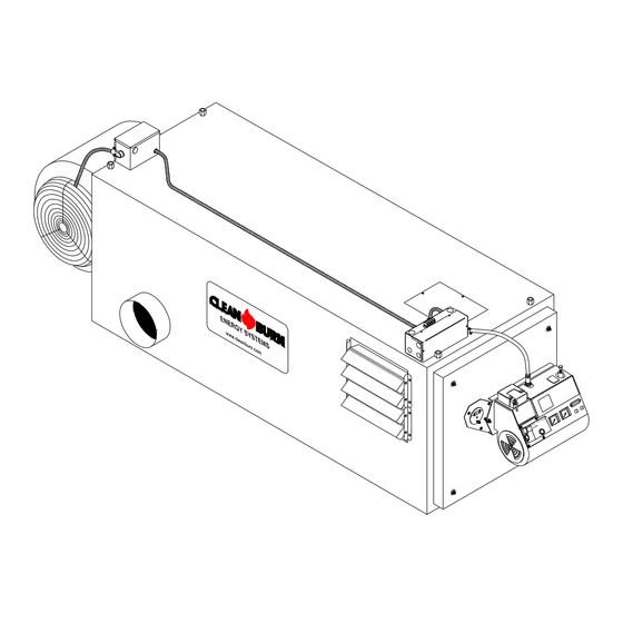
CLEAN BURN MODELS: CB-1500 and CB-2500 MULTI-OIL FURNACES
230 V / 50 Hz
FOR YOUR SAFETY -
DO NOT STORE GASOLINE
OR OTHER FLAMMABLE VAPORS AND LIQUIDS
IN THE VICINITY OF THIS OR ANY APPLIANCE!!
PUBLICATION DATE: 6/1/10, Rev. 4
WARNING: DO NOT assemble, install, operate, or maintain this equipment without first
reading and understanding the information provided in this manual. Installation and
service must be accomplished by qualified personnel. Failure to follow all safety precautions
and procedures as stated in this manual may result in property damage, serious personal injury
or death.
CLEAN BURN, INC. • 34 Zimmerman Road • Leola, PA 17540 • U.S.A.
The Clean Burn logo is a trademark of Clean Burn, Inc. All other brand or product names mentioned are the registered
trademarks or trademarks of their respective owners.
Copyright © 2009 Clean Burn, Inc. All rights reserved. No part of this publication may be reproduced, or distributed without
the prior written permission of Clean Burn, Inc. 34 Zimmerman Road, Leola, PA 17540. Subject to change without notice.
OPERATOR'S MANUAL
with CB-500 Series Burner
I88942
CLEAN BURN PART # 43161
Advertisement
Table of Contents

Related Manuals for CLEAN BURN CB-1500


Summary of Contents for CLEAN BURN CB-1500
- Page 1 CLEAN BURN, INC. • 34 Zimmerman Road • Leola, PA 17540 • U.S.A. The Clean Burn logo is a trademark of Clean Burn, Inc. All other brand or product names mentioned are the registered trademarks or trademarks of their respective owners.
-
Page 3: Declaration Of Conformity
34 Zimmerman Rd. Leola, PA European Re presentative: Please call 1-800-331-0183 for authorized European distributors Equipment: CB-1500 CE # 90191 CB-2500 CE # 90158 EMC Competent Body: TÜV Rheinland Product Safety GmbH Am Grauenstein, D-51105 Köln I hereby declare that the above named machinery complies with Essential Health and Safe ty Requirements of the Industrial Machinery Directive (IM D - 98/37/EEC) as amended, with the Low Voltage Directive (LVD –... -
Page 5: Table Of Contents
TABLE OF CONTENTS SECTION 1: INTRODUCTION ..................1-1 Guide to this Manual ......................1-1 For Your Safety........................ 1-2 Guidelines for Furnace Usage ................... 1-4 Guidelines for Used Oil Tanks .................. 1-5 Safety Labels ......................1-6 SECTION 2: UNPACKING ..................2-1 Removing the Shipping Crate .................. - Page 6 TABLE OF CONTENTS SECTION 4: FURNACE INSTALLATION (continued) Oil Tank Installation Specifications ................. 4-8 Installing the Tank Vent and Emergency Vent ............4-9 Installing the Metering Pump ..................4-10 Preparing for Installation ..................4-10 Standard Mounting: Vertical Positioning ..............4-10 Alternate Mounting: Horizontal Positioning ............
- Page 7 Furnace Dimensions ....................A-3 Burner Components ....................A-4 Removing the Nozzle for Cleaning ................. A-9 Furnace Components ....................A-10 CB-1500 Furnace Components ................A-10 CB-2500 Furnace Components ................A-12 Blower Components ....................A-14 CB-1500 Blower Components ................A-14 CB-2500 Blower Components ................A-16 APPENDIX B Wiring Diagrams .......................
- Page 8 TABLE OF CONTENTS APPENDIX C Additional Installation and Maintenance Requirements ..........C-1 Installing a Cover over the Oil/Air Regulators ............C-1 Installing a Fire Valve ....................C-2 APPENDIX D Furnace Service Record ....................D-1...
-
Page 9: Section 1: Introduction
This manual contains all the information necessary to safely install and operate the Clean Burn CE-certified, 230 V / 50 Hz Furnace Models CB-1500 and CB-2500. Consult the Table of Contents for a detailed list of topics covered. You'll find this manual's step-by-step procedures easy to follow and understand. -
Page 10: For Your Safety
Operator's Manual: Models CB-1500 & CB-2500 (230 V / 50 Hz) For Your Safety... For your safety, Clean Burn documentation contains the following types of safety statements (listed here in order of increasing intensity): • NOTE: A clarification of previous information or additional pertinent information. -
Page 11: Maintenance
Clean Burn, Inc. Unauthorized modifications or alteration can adversely affect the proper, safe operation of your furnace. WARNING: The burner which is shipped with your Clean Burn furnace is to be used only with your furnace according to the instructions provided in this manual. DO NOT use the... -
Page 12: Guidelines For Furnace Usage
Contact your local Clean Burn dealer for current environmental regulations. • If your furnace ever requires service, call your Clean Burn dealer. DO NOT allow untrained, unauthorized personnel to service your furnace. Make sure that your furnace receives annual preventative maintenance to ensure optimal performance. -
Page 13: Guidelines For Used Oil Tanks
Operator's Manual: Models CB-1500 & CB-2500 (230 V / 50 Hz) For Your Safety... (continued) Guidelines for Used Oil Tanks For the safe storage of used oil and the safety of persons in the vicinity of the used oil supply tank,... -
Page 14: Safety Labels
If any labels on your Clean Burn furnace ever become worn, lost or painted over, please call your Clean Burn dealer for free replacements. - Page 15 Operator's Manual: Models CB-1500 & CB-2500 (230 V / 50 Hz) For Your Safety... (continued) CB-1500/CB-2500 Furnace Cabinet Safety Labels...
- Page 16 Operator's Manual: Models CB-1500 & CB-2500 (230 V / 50 Hz) For Your Safety... (continued) CB-1500/CB-2500 Furnace Cabinet Safety Labels CLEAN BURN, INC. CLEAN BURN, INC. LEOLA, PENNSYLVANIA (USA) LEOLA, PENNSYLVANIA (USA) CB 1500 BTU/HR (KW) CB 2500 150,000 BTU/HR...
- Page 17 Operator's Manual: Models CB-1500 & CB-2500 (230 V / 50 Hz) For Your Safety... (continued) CB-1500/CB-2500 Burner Labels Label Part # Description 42004 Burner Safety Warning Label (High Voltage/Moving Parts Hazards) 42235 Burner Safety Warning Label (Fire/Explosion Hazard - Burner Installation and Service)
- Page 18 Operator's Manual: Models CB-1500 & CB-2500 (230 V / 50 Hz) 1-10...
-
Page 19: Section 2: Unpacking
Unpacking and Inspecting All Components Following is an itemized list of all components you should have received in your Clean Burn furnace shipment. Open all shipping containers and inspect all components according to the list. Immediately notify the freight company and your Clean Burn dealer in case of shipping damage or shortage(s). -
Page 20: Unpacking Items Packed Inside The Furnace
Operator's Manual: Models CB-1500 & CB-2500 (230 V / 50 Hz) Unpacking Items Packed Inside the Furnace To unpack the items packed inside the furnace cabinet (in the combustion chamber), you will need to open the combustion chamber door. Remove the four nuts and washers which hold the combustion chamber door closed. Set the nuts and washers aside in a safe place for later re-installation after the target has been installed (Section 3). -
Page 21: Section 3: Furnace Assembly
(4) Installing the Burner (5) Installing the Connector Block, Oil Line Tubing, and Air Line Tubing Clean Burn recommends that you review all assembly procedures before proceeding, paying careful attention to safety information statements. Figure 3A on the following page provides a general overview of the furnace components and their proper assembly. - Page 22 IT IS OK TO OPEN OR RESTRICT THE LOUVERS AS NEEDED, AND THEN I88943 TO TURN THOSE CONFIGURATIONS IN ANY OF FOUR DIRECTIONS Complete assembly of the CB-1500/CB-2500 furnace according to the following list of activities as illustrated above: (1) Installing the Blower Assembly...
-
Page 23: Installing The Blower Assembly
Remove the blower stabilizer brackets as shown in Figure 3B. (These braces, which are installed at the factory, are designed to keep the blower in proper position during shipping. Note that these braces are provided on CB-2500 blower assemblies ONLY; CB-1500 blower assemblies do not require these special shipping braces.) Position the blower over the opening in the back of the furnace cabinet by sliding the blower into the mounting angle brackets. -
Page 24: Wiring The Blower Motor
Operator's Manual: Models CB-1500 & CB-2500 (230 V / 50 Hz) Installing the Blower Assembly (continued) Black Motor Lead − Orange Wire White Motor Lead − White Wire Brown Motor Leads − Capacitor Green Wire − Ground Screw Note: CB-1500 is shown; CB-2500 Junction Box and Motor are mounted on the opposite side of the blower. -
Page 25: Determining The Hot Air Discharge Configuration
Unit Heater Configurations as stated in Section 4 of this manual. CB-1500 Equipped with two (2) louver sections and four (4) blank cover panels CB-2500 Equipped with three (3) louver sections and three (3) blank cover panels (2) Central Furnace (A) Furnace with blower assembly for DUCTING applications with 0.06 kPa... -
Page 26: Installing The Hot Air Discharge Components
CB-1500 opening in side shrouding for ductwork - 305 mm x 305 mm (12" x 12") NO changes need to be made for the shrouding outlet size CB-2500 opening in side shrouding for ductwork - 395 mm x 395 mm (15 1/2"... - Page 27 Refer to Figures 3D and 3E. Determine the desired air flow discharge pattern. Note that the CB-1500 is supplied with (2) louver sections and (4) blank cover panels. The CB-2500 is supplied with (3) louver sections and (3) blank cover panels. Air discharge openings are: (1) on each side of the furnace, and (1) on the bottom of the furnace.
- Page 28 Louvers split between both sides and bottom openings, showing left and right side views of same furnace I88945 Figure 3E - Sample Split Louver Installations for Partial Air Discharge on Sides and/or Bottom. CB-2500 is shown. CB-1500 is similar with two (2) louver sets and four (4) blank cover panels.
-
Page 29: Installing The Energy Retention Disc
Checking the Burner Nozzle and Electrodes NOTE: The burner nozzle is factory installed. Both furnace models (CB-1500, CB-2500) use a Delavan 9-5 nozzle. The nozzle size is indicated on the nozzle as shown in Figure 3F on the following page. Refer also to Appendix A at the back of the manual for additional specifications/instructions on the burner nozzle. - Page 30 Operator's Manual: Models CB-1500 & CB-2500 (230 V / 50 Hz) Installing the Burner (continued) BURNER NOZZLE NOZZLE IS STAMPED WITH SIZE ON FLAT OF NOZZLE HEAD SIDE VIEW − AA 5 mm (3/16") GAP BETWEEN ELECTRODES & NOZZLE CRITICAL DIMENSION: NOZZLE MUST BE 3 mm (1/8") AHEAD OF THE...
-
Page 31: Mounting The Burner On The Hinge Bracket
Operator's Manual: Models CB-1500 & CB-2500 (230 V / 50 Hz) Installing the Burner (continued) Mounting the Burner on the Hinge Bracket ATTENTION: Burner tube components (e.g. electrodes and retention head) are factory set. Handle the burner with extreme care so that burner components are not damaged. -
Page 32: Installing The Connector Block, Oil Line Tubing, And Air Line Tubing
Operator's Manual: Models CB-1500 & CB-2500 (230 V / 50 Hz) Installing the Connector Block, Oil Line Tubing, and Air Line Tubing ATTENTION: DO NOT use teflon tape on any fittings. Teflon tape residues will plug vital burner components. Installing the Connector Block on the Furnace Door OIL LINE Refer to Figure 3G. -
Page 33: Installing The Air Line Tubing
Operator's Manual: Models CB-1500 & CB-2500 (230 V / 50 Hz) Installing the Connector Block, Oil Line Tubing, and Air Line Tubing (continued) Installing the Oil Line Tubing (continued) Make sure that the curl in the oil line is positioned as shown in Figure 3G so that the burner can swing open correctly. -
Page 34: Locking The Burner Into Firing Position
Operator's Manual: Models CB-1500 & CB-2500 (230 V / 50 Hz) Locking the Burner Into Firing Position Swing the burner into firing position. Install and tighten the lock-down nut on the mounting plate bolt to secure the burner in its firing position. -
Page 35: Section 4: Furnace Installation
(9) Installing the Wall Thermostat (10) Inspecting the Installation Clean Burn recommends that you review all procedures before beginning installation, paying careful attention to safety information statements. Figures 4A and 4B provide a general overview of a typical furnace installation and should be reviewed closely before proceeding. - Page 36 WARNING: Low voltage terminals are only protected by basic insulation--caution is required. CAUTION: Use only approved wire conduit and connectors when wiring the Clean Burn furnace. An emergency stop device (i.e. "panic button") must be installed at ground level in the mains cable to the furnace to ensure the safety of furnace operators and service personnel.
- Page 37 Operator's Manual: Models CB-1500 & CB-2500 (230 V / 50 Hz) WARNING! NEVER LOCATE A STACK JOINT INSIDE WALLS OR IN A JOIST SPACER. DO NOT CREATE FIRE HAZARDS! NOTE: THE LAST STACK SECTION SHALL EXTEND AT LEAST 92 cm (3 FT)
- Page 38 PERIODICALLY SHUT DOWN ON SAFETY LOCKOUT CANISTER FILTER IN SUCTION LINE EMERGENCY VENT VALVE VENT PIPE WITH VENT CHECK VALVE INSTALL WITH ARROW UP CHECK VALVE SCREEN OIL STORAGE TANK CLEAN OUT I88891−B Figure 4B - Typical CB-2500 Furnace Installation - Detailed (CB-1500 is similar)
-
Page 39: Selecting A Location
Operator's Manual: Models CB-1500 & CB-2500 (230 V / 50 Hz) Selecting a Location Guidelines for Selecting a Location The location you select for your furnace must allow the following: • Unobstructed, even heat distribution. • Safe, easy access for servicing. -
Page 40: Mounting The Furnace
Operator's Manual: Models CB-1500 & CB-2500 (230 V / 50 Hz) Selecting a Location (continued) 5 cm (2") 31 cm (12") REAR 46 cm (18") OTHER SIDE (WITHOUT AIR DISCHARGE) 46 cm (18") CHIMNEY CONNECTOR 153 cm (60") FRONT 153 cm (60") -
Page 41: Raised Platform Mounting
MIN. 24 GA STEEL 2 PIECES FIREGUARD SHEETROCK OR EQUIVALENT COMBUSTIBLE MATERIAL MIN. 5 cm (2") TALL MASONRY BLOCKS TO ALLOW CLEARANCE FOR INSTALLATION OF I88894 FITTINGS ON THE CONNECTOR BLOCK Figure 4E - CB-1500 Furnace Installed on Non-Combustible Floor (CB-2500 is similar) -
Page 42: Oil Tank Installation Specifications
Operator's Manual: Models CB-1500 & CB-2500 (230 V / 50 Hz) Oil Tank Installation Specifications Ensure that your tank installation adheres to the following safety guidelines as stated here and in Section 1 of this manual. The tank safety label (shown at right) also summarizes these important specifications for tank installation and usage. -
Page 43: Installing The Tank Vent And Emergency Vent
Codes require that you install a tank vent (to the outside) and an emergency vent for your tank as shown in Figure 4F. Tank Vent Kits are available from Clean Burn; contact your local Clean Burn dealer to order. Be sure to check your local codes for any additional tank installation requirements, and adhere to the following installation guidelines: •... -
Page 44: Installing The Metering Pump
Operator's Manual: Models CB-1500 & CB-2500 (230 V / 50 Hz) Installing the Metering Pump Preparing for Installation Before starting installation of the metering pump, review Figures 4G, 4H, and 4I to become familiar with the metering pump components. You will also need to accomplish the following activities: •... - Page 45 Operator's Manual: Models CB-1500 & CB-2500 (230 V / 50 Hz) PART # DESCRIPTION see chart GEARMOTOR 11322 MOUNT − METER PUMP 32037 1/8 NPT X 1/4 TUBE COMPRESSION FITTING 1/4 COPPER OR ALUM. TUBING 32140 LONG NUT 1/2 1/2 COPPER OR ALUM. TUBING 32141 FLARED TUB.
-
Page 46: Alternate Mounting: Horizontal Positioning
Operator's Manual: Models CB-1500 & CB-2500 (230 V / 50 Hz) Installing the Metering Pump (continued) Alternate Mounting: Horizontal Positioning ATTENTION: If the metering pump is to be mounted horizontally or on a bracket as shown in Figure 4I, the pump head must be rotated counterclockwise so that it is aligned in a horizontal position. -
Page 47: Wiring The Furnace And Pump
Operator's Manual: Models CB-1500 & CB-2500 (230 V / 50 Hz) Wiring the Furnace and Pump WARNING: To avoid electrical shock, make sure that power to the furnace is turned OFF before connecting any wires. A licensed electrician should install all wiring to your furnace. All wiring must be in accordance with national and local codes. -
Page 48: Installing The Suction Oil Line Components
Operator's Manual: Models CB-1500 & CB-2500 (230 V / 50 Hz) Installing the Suction Oil Line Components ATTENTION: It is critical that you adhere to the following specifications for suction oil line installation (oil line from the tank to the pump). If these specifications are not met, the metering pump will not function correctly and the burner will shut down on reset. - Page 49 Operator's Manual: Models CB-1500 & CB-2500 (230 V / 50 Hz) Installing the Suction Oil Line Components (continued) (1.) (e.) Prepare the canister filter for installation (continued): • Install this assembly into one side of the 1/2" brass tee. •...
- Page 50 Operator's Manual: Models CB-1500 & CB-2500 (230 V / 50 Hz) Install the suction oil line (from the the tank to the canister filter): a. Refer to Figures 4H and/or 4J. b. Prepare a piece of 1/2" O.D. copper tubing (user-supplied) which will function as the pick-up line from the tank to the canister filter.
-
Page 51: Installing The Pressure Relief Oil Line Back To The Tank
Operator's Manual: Models CB-1500 & CB-2500 (230 V / 50 Hz) Installing the Pressure Relief Oil Line Back to the Tank ATTENTION: It is critical that you adhere to the following specifications for plumbing the pressure relief back to the tank. -
Page 52: Installing The Pressure Oil Line Components
Operator's Manual: Models CB-1500 & CB-2500 (230 V / 50 Hz) Installing the Pressure Oil Line Components ATTENTION: It is critical that you adhere to the following specifications for pressure oil line installation (oil line from the pump to the furnace); if these specifications are not met, the metering pump will not function correctly and the burner will shut down on reset. -
Page 53: Installing The Stack
Installing the Stack WARNING: Inappropriate stack materials or improper stack design/installation can adversely affect the proper, safe operation of your furnace. Contact your Clean Burn dealer to purchase the proper stack components for your furnace. Stack designs are generally classified as follows: (1) "Class A"... - Page 54 Operator's Manual: Models CB-1500 & CB-2500 (230 V / 50 Hz) Installing the Stack (continued) "CLASS A" STACK CAP − NON−RESTRICTIVE TYPE TO ALLOW FREE FLOW OF THE STACK GASES NOTE: THE LAST STACK SECTION SHALL EXTEND AT LEAST WARNING! ENSURE PROPER 90 cm (3’) ABOVE THE HIGHEST POINT AT WHICH IT COMES IN...
- Page 55 Operator's Manual: Models CB-1500 & CB-2500 (230 V / 50 Hz) Installing the Stack (continued) "CLASS A" STACK CAP − NON−RESTRICTIVE TYPE TO ALLOW FREE FLOW OF THE STACK GASES WARNING! ENSURE PROPER CLEARANCES BETWEEN STACK COMPONENTS AND COMBUSTIBLES PER ALL APPLICABLE CODES.
-
Page 56: Installing The Interior Stack
Operator's Manual: Models CB-1500 & CB-2500 (230 V / 50 Hz) Installing the Interior Stack WARNING: Single wall stack components may be used only for those portions of the stack which are located inside your building and away from any fire/burn hazards. -
Page 57: Installing The Stack Penetration
ATTENTION: The draft inducer, Field brand model DI-2, is optional equipment and may be installed to ensure proper draft. The Field brand draft inducer has been tested for use on Clean Burn furnaces. DO NOT use other models or brands of draft inducers. - Page 58 Operator's Manual: Models CB-1500 & CB-2500 (230 V / 50 Hz) Installing the Optional Draft Inducer (continued) "CLASS A" STACK (DOUBLE−WALL INSULATED ALL−FUEL STACK ) OPTIONAL DRAFT INDUCER NOTE: INSTALL DRAFT INDUCER IN LAST SECTION OF VERTICAL STACK TO POSITION...
-
Page 59: Installing The Wall Thermostat
Operator's Manual: Models CB-1500 & CB-2500 (230 V / 50 Hz) Installing the Optional Draft Inducer (continued) Installing the Draft Inducer WARNING: Turn OFF the main power to the furnace before proceeding with the installation of the draft inducer. ATTENTION: It is very important to install the draft inducer on a vertical section of stack to isolate the inducer from excessive heat and ash buildup. - Page 60 Operator's Manual: Models CB-1500 & CB-2500 (230 V / 50 Hz) 4-26...
-
Page 61: Section 5: Metering Pump Priming
Operator's Manual: Models CB-1500 & CB-2500 (230 V / 50 Hz) SECTION 5: METERING PUMP PRIMING Understanding Metering Pump Priming Preparing your Clean Burn furnace for operation begins with priming the metering pump. The procedures in this section must be performed in sequence without interruption to properly prime the pump. -
Page 62: Priming The Metering Pump
Operator's Manual: Models CB-1500 & CB-2500 (230 V / 50 Hz) Priming the Metering Pump ATTENTION: The priming process must be done precisely as described in this procedure to ensure that all air is thoroughly bled from the system. Failure to bleed all air from the system will result in repeated burner shutdowns on reset. - Page 63 Operator's Manual: Models CB-1500 & CB-2500 (230 V / 50 Hz) Priming the Metering Pump (continued) Activating the Pump NOTE: The furnaces features a priming switch which is mounted on the right-hand side of the electrical junction box on the front of the furnace cabinet. The priming switch has two positions: •...
-
Page 64: Vacuum Testing The Oil Pump
Operator's Manual: Models CB-1500 & CB-2500 (230 V / 50 Hz) Priming the Metering Pump (continued) Run the pump until a solid stream of oil flows from the pump bleeder. This will bleed all air out of the suction line, oil filter and pump head. - Page 65 Operator's Manual: Models CB-1500 & CB-2500 (230 V / 50 Hz) Vacuum Testing the Oil Pump (continued) If there are no suction leaks, the system will hold vacuum. NOTE: It is acceptable for the vacuum to drop one to five inches within one minute as the seal in the pump seats.
- Page 66 Operator's Manual: Models CB-1500 & CB-2500 (230 V / 50 Hz)
-
Page 67: Section 6: Starting And Adjusting The Burner
Operator's Manual: Models CB-1500 & CB-2500 (230 V / 50 Hz) SECTION 6: STARTING AND ADJUSTING THE BURNER Understanding Burner Startup and Adjustment Starting and adjusting the burner involves a series of separate procedures which must be accomplished in sequence without interruption. Review all the procedures before attempting burner startup and adjustment, paying careful attention to safety information statements. - Page 68 NOTE: The oil pressure is automatically adjusted by the metering pump. The approximate oil pressure range during initial startup is 0.07 to 0.28 bar (1 to 4 psi) for Model CB-1500, and 0.28 to 0.55 bar (4 to 8 psi) for Model CB-2500.
-
Page 69: Starting The Burner
Operator's Manual: Models CB-1500 & CB-2500 (230 V / 50 Hz) Starting the Burner Turn the switch on the wall thermostat to HEAT and adjust the thermostat setting above room temperature to start the burner. NOTE: If the burner refuses to start, review the Preparing the Burner for Startup procedure. If,... -
Page 70: Checking The Operation Of The Blower Motor
The fan switch will then shut off the motor. WARNING: If the blower motor does not operate as described, immediately shut down your furnace to avoid potential equipment damage and/or fire hazard. Contact your Clean Burn dealer immediately. -
Page 71: Section 7: Resetting The Furnace And Burner
• If the burner still will not restart, contact your Clean Burn Distributor for immediate service. Understanding the Oil Primary Control The oil primary control will shut the oil pump and oil solenoid off when it detects flame-out during burner operation. -
Page 72: The Blower/Fan Switch
The Hi-Temp Limit Switches The CB-1500/CB-2500 furnaces also feature two high temperature limit switches which are mounted on a bracket at the front of the combustion chamber as shown in Figure 7B. The switches sense the build up of heat within the combustion chamber and are designed to protect the furnace from damage due to overheating. - Page 73 Operator's Manual: Models CB-1500 & CB-2500 (230 V / 50 Hz) CLEAN−OUT BREECH COMBUSTION CHAMBER CLEAN−OUT CAP (33230) F−180 33288 L−290 HI LIMIT AUXILIARY SURFACE MOUNT SWITCH (AUTO RESET) FAN SWITCH BLACK & TAN WIRE FROM TERMINAL BLOCK RED & TAN WIRE LINKS THE 2 SWITCHES IN SERIES (33390) L−200...
- Page 74 Operator's Manual: Models CB-1500 & CB-2500 (230 V / 50 Hz)
-
Page 75: Section 8: Adjusting The Draft Overfire
Operator's Manual: Models CB-1500 & CB-2500 (230 V / 50 Hz) SECTION 8: ADJUSTING THE DRAFT OVERFIRE Understanding the Importance of Draft Draft in the furnace is created as the hot combustion gases rise up the stack, creating a negative pressure inside the stack and the furnace. -
Page 76: Adjusting The Barometric Damper
Operator's Manual: Models CB-1500 & CB-2500 (230 V / 50 Hz) Adjusting the Barometric Damper NOTE: If the draft overfire is not in the -.02 to -.04 w.c. range, it is necessary to adjust the barometric damper. Before starting the burner, turn the weight on the flapper COUNTERCLOCKWISE until the flapper remains closed. -
Page 77: Understanding The Effect Of Exhaust Fans On Draft
Operator's Manual: Models CB-1500 & CB-2500 (230 V / 50 Hz) Understanding the Effect of Exhaust Fans on Draft Any type of exhaust fan, paint booth, or exhaust system in a building will create negative pressure in the building unless there is a source of make-up air (i.e. fresh air which enters the building and replaces the air removed by the exhaust fans.) Refer to Figure 8C on the following page. - Page 78 Operator's Manual: Models CB-1500 & CB-2500 (230 V / 50 Hz) EXHUST FAN CREATES BACKDRAFT IN STACK AND SUCKS COMBUSTION GASES DOWN THE STACK AND BACK INTO THE FURNACE BACKDRAFT To arrive at proper OIL SPRAY AND HEAT IS FORCED...
-
Page 79: Installing A Make-Up Air Louver
Operator's Manual: Models CB-1500 & CB-2500 (230 V / 50 Hz) Installing a Make-up Air Louver Exhaust Fans and Make-up Air Louvers When exhaust fans are operated in tight buildings, there is little or no source of fresh air to replace the air removed from the building by the exhaust fan. - Page 80 Operator's Manual: Models CB-1500 & CB-2500 (230 V / 50 Hz) Installing a Make-up Air Louver (continued) CALCULATED OPENING SIZE REQUIRED LOUVER / GRILL SIZE 0 – 528 0 – 82 25 x 25 10 x 10 529 – 836 83 –...
-
Page 81: Section 9: Maintenance
SECTION 9: MAINTENANCE Understanding Maintenance Servicing your Clean Burn furnace in a timely manner is very important to keep your furnace running in peak condition. Just as an automobile requires periodic maintenance such as oil changes, engine tune-ups, etc. your Clean Burn furnace also requires regularly scheduled service. -
Page 82: Periodic Burner Inspection
Operator's Manual: Models CB-1500 & CB-2500 (230V / 50 Hz) Periodic Burner Inspection Following initial start up of the burner, you should inspect the operation of the burner periodically--ideally on a monthly basis. Doing so ensures that the system is functioning efficiently and safely. -
Page 83: Cleaning The Canister Filter
Operator's Manual: Models CB-1500 & CB-2500 (230V / 50 Hz) Cleaning the Canister Filter ATTENTION: Never operate your furnace with more than 10" HG of vacuum on the suction side of the pump. High vacuum separates air from the oil and results in erratic burner operation. -
Page 84: Servicing The Metering Pump
Operator's Manual: Models CB-1500 & CB-2500 (230V / 50 Hz) Servicing the Metering Pump Refer to Figure 9C. Remove the pump head cover (part 1). Remove the screen (part 2) and wash it. Remove and discard the used gasket (part 3). -
Page 85: Cleaning Ash From The Furnace
#12 copper wire wrapped around the hose with the other end connected to the furnace (or other ground source) to eliminate the static. CLEAN-OUT DOOR CLEAN-OUT BREECH CLEAN-OUT CAP I88949 COMBUSTION CHAMBER Figure 9D - Accessing the CB-1500 Combustion Chamber for Cleaning (CB-2500 is similar) - Page 86 ATTENTION: The presence of rust in the flues indicates that chlorinated materials are being burned. Burning chlorinated materials will severely damage your heat exchanger. Contact your Clean Burn dealer for instructions to test your oil for chlorine contamination before firing your furnace.
-
Page 87: Cleaning The Check Valve / Screen
Operator's Manual: Models CB-1500 & CB-2500 (230V / 50 Hz) Cleaning Ash From the Furnace (continued) k. Re-install the furnace components: Swing the clean-out door shut; install and tighten the lock-down nuts so that the door seals properly. Re-install the air and oil lines on the bottom of the connector block. -
Page 88: Cleaning The Tank
Clean Burn service technician who has the necessary parts and expertise.. Contact your local Clean Burn dealer to schedule the annual periodic maintenance which is usually (preferably) performed during warm weather to prepare the furnace for the next heating season. Various levels of service are provided to fit your particular need. -
Page 89: Section 10: Troubleshooting
Operator's Manual: Models CB-1500 & CB-2500 (230 V / 50 Hz) SECTION 10: TROUBLESHOOTING The following charts and tables are provided for reference in troubleshooting any difficulties encountered in furnace operation and adjustment. • The Flow Chart outlines the proper sequence of events in furnace operation -- use this chart to help diagnose where a problem may be occurring. - Page 90 Operator's Manual: Models CB-1500 & CB-2500 (230 V / 50 Hz) 10-2...
- Page 91 Operator's Manual: Models CB-1500 & CB-2500 (230 V / 50 Hz) PROBLEM POSSIBLE CAUSE POSSIBLE ACTION(S) Burner won’t run at all and Circuit breaker/main switch open. Close circuit breaker/switch. Green power light is NOT ON. Fuse/breaker blown. Electrician should check out electrical system.
- Page 92 Operator's Manual: Models CB-1500 & CB-2500 (230 V / 50 Hz) PROBLEM POSSIBLE CAUSE POSSIBLE ACTION(S) Burner ignites, but will not stay running There is a fuel delivery problem. Follow the procedures listed in the and Burner shuts off on reset within 15 next problem.
- Page 93 Operator's Manual: Models CB-1500 & CB-2500 (230 V / 50 Hz) PROBLEM POSSIBLE CAUSE POSSIBLE ACTION(S) Burner ignites and Burner shuts off on There is air in the fuel supply. Prime the pump. If the pump will reset sometime later during the day or not prime or there is air in the oil night.
- Page 94 Operator's Manual: Models CB-1500 & CB-2500 (230 V / 50 Hz) PROBLEM POSSIBLE CAUSE POSSIBLE ACTION(S) Pump will not prime and Pump motor is There is a leak(s) in the suction Follow the specifications in running. line. Section 4 to make sure the...
- Page 95 Operator's Manual: Models CB-1500 & CB-2500 (230 V / 50 Hz) PROBLEM POSSIBLE CAUSE POSSIBLE ACTION(S) Pump wil l not prime and Pump motor i s There is NO power on t he Sta rt the burner a nd a djust th e a ir NOT running.
- Page 96 Operator's Manual: Models CB-1500 & CB-2500 (230 V / 50 Hz) 10-8...
-
Page 97: Detailed Furnace Specifications
Operator's Manual: Models CB-1500 & CB-2500 (230 V / 50 Hz) APPENDIX A Detailed Furnace Specifications Furnace Technical Specifications Furnace Model CB-1500 CB-2500 Input 44 KW @ 4 LTR/HR 77 KW @ 6.4 LTR/HR (150,000 @ 1.1 GPH) (250,000 @ 1.7 GPH) -
Page 98: Burner Technical Specifications
Operator's Manual: Models CB-1500 & CB-2500 (230 V / 50 Hz) Burner Technical Specifications Burner CB-500-CE-5W Ignition Transformer Danfoss (14,000 Volts) Nozzle Delavan 9-5 Burner Motor 1/10 HP 2800 RPM with centrifugal switch Burner Motor Rotation CCW shaft end Compressed Air Requirements 0.06 CMM @ 1.7 Bar... -
Page 99: Furnace Dimensions
Operator's Manual: Models CB-1500 & CB-2500 (230 V / 50 Hz) Furnace Dimensions FURNACE DIMENSIONS NOTE: MEASUREMENT FROM BOLT CENTER TO BOLT CENTER IS 1753 mm (69 IN.) CB−2500 1753 mm 19 mm (69") (3/4") 755 mm 476 mm (29 3/4) (18 3/4") 673 mm... -
Page 100: Burner Components
Operator's Manual: Models CB-1500 & CB-2500 (230 V / 50 Hz) Burner Components DETAIL B OIL GUAGE DETAIL A AIR GAUGE BURNER I89016 CB-500 CE 5W Figure A1 - CB-500-CE 5W Burner Component Detail... - Page 101 Operator's Manual: Models CB-1500 & CB-2500 (230 V / 50 Hz) Burner Components (continued) Item # Pa rt # Des cription Item # Pa rt # Desc ription 11 265 CO VER - HINGED W A 335 28 SP ARK PLUG CA BLE...
- Page 102 Operator's Manual: Models CB-1500 & CB-2500 (230 V / 50 Hz) Burner Components (continued) I88852 Figure A2 - Preheater Block and Electrode Assembly Component Detail...
- Page 103 Operator's Manual: Models CB-1500 & CB-2500 (230 V / 50 Hz) Burner Components (continued) Item# C.B. Part# Qty. Component Description 34169 ELECTRODE SCREW - 10-32 x 3/4 33527 PLUG IN ELECTRODE 34165 WASHER 32000 9 - 5 NOZZLE 13150 NOZZLE ADAPTOR...
- Page 104 Operator's Manual: Models CB-1500 & CB-2500 (230 V / 50 Hz) Burner Components (continued) INSTALLATION OF THE SPINNER RETENTION HEAD THE SPINNER RETENTION HEAD FITS INSIDE THE BURNER TUBE AND REQUIRES (3) SELF−TAPPING SCREWS. IT IS VERY IMPORTANT THAT THE SPINNER HEAD IS NOT TIPPED FROM SIDE TO SIDE OR FROM TOP TO BOTTOM.
-
Page 105: Removing The Nozzle For Cleaning
Check the electrodes for proper gap and clearances. (Figure A3) Re-install the burner and adjust for optimal performance as described in Section 6. NOTE: If the nozzle plugs within a few days after cleaning, call your Clean Burn Dealer for service. Figure A4 - Cleaning the Nozzle... -
Page 106: Cb-1500 Furnace Components
Operator's Manual: Models CB-1500 & CB-2500 (230 V / 50 Hz) CB-1500 Furnace Components CABINET CB-1500-5W CE & R (CE # 11531 and R # 11510) DETAIL C DETAIL B DETAIL A DETAIL D I88909 Figure A5 - CB-1500 Furnace Component Detail... - Page 107 Operator's Manual: Models CB-1500 & CB-2500 (230 V / 50 Hz) CB-1500 Furnace Components (continued) Ite m Item Pa rt # Des cription P art # De script ion 31 091 DUCT CA P RO UND 8" 3 314 2...
-
Page 108: Cb-2500 Furnace Components
Operator's Manual: Models CB-1500 & CB-2500 (230 V / 50 Hz) CB-2500 Furnace Components CABINET CB-2500 CE & R 5W (CE # 11480 and R # 11511) DETAIL A DETAIL C DETAIL B DETAIL D I88910 Figure A6 - CB-2500 Furnace Component Detail... - Page 109 Operator's Manual: Models CB-1500 & CB-2500 (230 V / 50 Hz) CB-2500 Furnace Components (continued) It em Item Part # De scription Pa rt # Desc ription 3109 1 DUCT CAP ROUND 8" 21 170 E-LID 2101 0 STA CK P IP E FL ASH RING...
-
Page 110: Blower Components
Operator's Manual: Models CB-1500 & CB-2500 (230 V / 50 Hz) CB-1500 Blower Components BLOWER ASSEMBLY CB-1500 I88954 Figure A7 - CB-1500 Blower Component Detail A-14... -
Page 111: Cb-1500 Blower Components
Operator's Manual: Models CB-1500 & CB-2500 (230 V / 50 Hz) CB-1500 Blower Components (continued) ITEM# PART# DESCRIPTION 34116 10 X 5/8 HEX WASHER HEAD TEK Z 31191 GUARD DD BLOWER 31204 BRACKET KIT - 3/4 HP MOTOR EA 31199... -
Page 112: Cb-2500 Blower Components
Operator's Manual: Models CB-1500 & CB-2500 (230 V / 50 Hz) CB-2500 Blower Components BLOWER ASSEMBLY CB-2500 I88956 Figure A8 - CB-2500 Blower Component Detail A-16... - Page 113 Operator's Manual: Models CB-1500 & CB-2500 (230 V / 50 Hz) CB-2500 Blower Components (continued) ITEM# PART# DESCRIPTION 31191 GUARD DD BLOWER 31189 BLOWER CB-2500 12057 FLEX CONDUIT RW 3/8 X 23 33055 WIRE PROTECTOR (anti-short) 33575 MOTOR 1 HP 230V/50Hz...
- Page 114 Operator's Manual: Models CB-1500 & CB-2500 (230 V / 50 Hz) A-18...
-
Page 115: Wiring Diagrams
Operator's Manual: Models CB-1500 & CB-2500 (230 V 50 Hz) APPENDIX B Wiring Diagrams GRND WHITE WHITE BLACK ORNG (OPTIONAL) STACK SAFETY THERMOSTAT SWITCH JMPR TO BLOWER 220 VOLT LIGHT GRND (PRIME ON) ORNG GRND BURNER POWER HOT (BLK) 220 VAC... -
Page 116: Burner Wiring Diagram
Operator's Manual: Models CB-1500 & CB-2500 (230 V 50 Hz) Wiring Diagrams (continued) Figure B2 - Burner Wiring Diagram... -
Page 117: Ladder Schematic
Operator's Manual: Models CB-1500 & CB-2500 (230 V 50 Hz) FURNACE & BURNER SCHEMATIC CB-1500/2500-CE 5W OPTIONAL SERVICE DISCONNECT SWITCH 44108 DWG. No..... NEUTRAL CIRC. FAN MOTOR BLOWER SWITCH (METAL SURFACE: 33230) 24 VOLTS OPTIONAL WALL THERMOSTAT STACK SAFETY SWITCH... -
Page 118: Metering Pump Wiring Schematics
Operator's Manual: Models CB-1500 & CB-2500 (230 V 50 Hz) Wiring Diagrams (continued) 230 V 50Hz POWER FROM OIL PUMP CIRCUIT (SEE FURNACE SCHEMATIC) INSULATE WITH WIRE NUTS μ GEARMOTOR ROTATION IS CCWSE AS SHOWN. TO REVERSE ROTATION, REVERSE RED & BLUE LEADS... -
Page 119: Additional Installation And Maintenance Requirements
Operator's Manual: Models CB-1500 & CB-2500 (230 V / 50 Hz) APPENDIX C Additional Installation and Maintenance Requirements The following activities must also be accomplished for furnace installations in the United Kingdom: • Installing a cover over the oil/air regulators on the burner •... -
Page 120: Installing A Fire Valve
Operator's Manual: Models CB-1500 & CB-2500 (230 V / 50 Hz) Installing a Fire Valve Install a fire valve element in a position above the burner as shown in Figure C2 to provide adequate protection in accordance with BS 5410 Parts 1 and 2. -
Page 121: Furnace Service Record
Operator's Manual: Models CB-1500 & CB-2500 (230 V / 50 Hz) APPENDIX D Furnace Service Record Furnace Purchased: Date __________ From (name/phone) _______________________________ Furnace Installed: Date __________ By (name/phone)__________________________________ Furnace Inspected: Date __________ By (name/phone)__________________________________ Note: Refer to Section 9 for Maintenance Instructions... - Page 122 Operator's Manual: Models CB-1500 & CB-2500 (230 V / 50 Hz)
Need help?
Do you have a question about the CB-1500 and is the answer not in the manual?
Questions and answers