Table of Contents
Advertisement
U.L. Listed Used Oil
Burning Appliance
#MH15393 (N)
U.L.-C Listed
#CMP217
PUBLICATION DATE: 8/15/07, Rev. 3
WARNING: DO NOT assemble, install, operate, or maintain this equipment without first
reading and understanding the information provided in this manual. Installation and
service must be accomplished by qualified personnel. Failure to follow all safety precautions
and procedures as stated in this manual may result in property damage, serious personal injury
or death.
IMPORTANT FOR U.S. INSTALLATIONS: All installations must be made in accordance with state and local codes
which may differ from the information provided in this manual. Save these instructions for reference.
IMPORTANT FOR CANADIAN INSTALLATIONS: These instructions have been reviewed and accepted by
Underwriters' Laboratories of Canada as being appropriate for the installation of the ULC labelled products
identified herein. The use of these instructions for the installation of products NOT bearing the ULC label and
NOT identified herein may result in an unacceptable or hazardous installation.
IMPORTANT FOR CANADIAN INSTALLATIONS: The installation of this equipment is to be accomplished by
qualified personnel and in accordance with the regulation of authorities having jurisdiction and CSA Standard B 139,
Installation Code for Oil Burning Equipment.
OPERATOR'S MANUAL
CLEAN BURN MODEL: CB-1400
MULTI-OIL FURNACE
with CB-525-S2 BURNER
I88817
CLEAN BURN PART # 43204
Advertisement
Table of Contents
Troubleshooting

Related Manuals for CLEAN BURN CB-1400


Summary of Contents for CLEAN BURN CB-1400
- Page 1 OPERATOR'S MANUAL CLEAN BURN MODEL: CB-1400 MULTI-OIL FURNACE with CB-525-S2 BURNER U.L. Listed Used Oil Burning Appliance #MH15393 (N) U.L.-C Listed #CMP217 I88817 PUBLICATION DATE: 8/15/07, Rev. 3 CLEAN BURN PART # 43204 WARNING: DO NOT assemble, install, operate, or maintain this equipment without first reading and understanding the information provided in this manual.
-
Page 3: Warranty Information
If the defect occurs in the first five (5) years (or 7500 hours, whichever comes first) , Clean Burn pays 100% of parts, replacement or repair (the customer pays 0%), and pro rata thereafter according to the following schedule: (a) If the defect occurs during the sixth year (or 7500-9000 hours, whichever comes first), customer pays 70% of parts, replacement or repair. - Page 4 TRADEMARKS The Clean Burn logo is a trademark of Clean Burn, Inc. All other brand or product names mentioned are the registered trademarks or trademarks of their respective owners. COPYRIGHT Copyright © 2007 Clean Burn, Inc. All rights reserved. No part of this publication may be reproduced, or distributed without...
-
Page 5: Table Of Contents
TABLE OF CONTENTS SECTION 1: INTRODUCTION ..................1-1 Guide to this Manual ......................1-1 For Your Safety ........................ 1-2 Guidelines for Furnace Usage ................... 1-4 Guidelines for Used Oil Tanks .................. 1-5 Safety Labels ......................1-6 SECTION 2: UNPACKING ..................2-1 Removing the Shipping Pallet .................. - Page 6 TABLE OF CONTENTS SECTION 4: FURNACE INSTALLATION (continued) Installing the Pressure Relief and Low-Flow Check Valve ........... 4-16 Installing the Pressure Oil Line Components ..............4-17 Installing the Compressed Air Line ................4-17 Installing the Stack ......................4-18 Stack Design and Specifications ................4-18 Installing the Interior Stack ..................
- Page 7 Cleaning the Nozzle ................... A-9 Fan Limit Control ....................A-10 APPENDIX B Wiring Diagrams ......................B-1 Furnace Wiring Diagram ..................B-1 Burner Wiring Diagram .................... B-2 CB-1400 Ladder Schematic ..................B-3 Metering Pump Wiring Schematic ................B-4 APPENDIX C Furnace Service Record ....................C-1...
-
Page 9: Section 1: Introduction
This manual contains all the information necessary to safely install and operate the Clean Burn Furnace Model CB-1400. Consult the Table of Contents for a detailed list of topics covered. You'll find this manual's step-by- step procedures easy to follow and understand. Should questions arise, please contact your Clean Burn dealer before starting any of the procedures in this manual. -
Page 10: For Your Safety
Operator's Manual: Model CB-1400 For Your Safety... For your safety, Clean Burn documentation contains the following types of safety statements (listed here in order of increasing intensity): • NOTE: A clarification of previous information or additional pertinent information. • ATTENTION: A safety statement indicating that potential equipment damage may occur if instructions are not followed. - Page 11 Clean Burn, Inc. Unauthorized modifications or alteration can adversely affect the proper, safe operation of your furnace. WARNING: The burner which is shipped with your Clean Burn furnace is to be used only with your furnace according to the instructions provided in this manual. DO NOT use the...
-
Page 12: Guidelines For Furnace Usage
Contact your Clean Burn dealer for current EPA regulations. • If your furnace ever requires service, call your Clean Burn dealer. DO NOT allow untrained, unauthorized personnel to service your furnace. Make sure that your furnace receives annual preventative maintenance to ensure optimal performance. -
Page 13: Guidelines For Used Oil Tanks
DO NOT use it. • If you do not have a copy of the tank safety label pictured at right, please contact your Clean Burn dealer for the label, which is to be affixed directly on your used oil supply tank. -
Page 14: Safety Labels
If any labels on your Clean Burn furnace ever become worn, lost or painted over, please call your Clean Burn dealer for free replacements. - Page 15 Operator's Manual: Model CB-1400 For Your Safety... (continued) CB-1400 Furnace Cabinet Safety Labels...
- Page 16 Operator's Manual: Model CB-1400 For Your Safety... (continued) CB-1400 Furnace Cabinet Safety Labels MH 15393 UNDERWRITERS’ LABORATORIES OF CANADA LISTED 10523 MULTI−OIL BURNING UNIT HEATER CB 1400 INPUT RATING W/NO 2 FUEL OIL (BTU/HR) 140000 15.0 15.0 15.0 15.0 POWER 1/20 0.75...
- Page 17 Operator's Manual: Model CB-1400 For Your Safety... (continued) CB-1400 Burner Labels Label Part # Description 42005 Sold and Serviced By Label 42004 Burner Safety Warning Label (High Voltage/Moving Parts Hazards) 42000 Burner Safety Warning Label 42197 (Fire/Explosion Hazard - Reset Button)
- Page 18 Operator's Manual: Model CB-1400 1-10...
-
Page 19: Section 2: Unpacking
NOTE: DO NOT attempt to slide the furnace out of the shipping crate - you may damage the furnace cabinet. Unpacking and Inspecting All Components Following is an itemized list of all components you should have received in your Clean Burn furnace shipment. Open all shipping containers and inspect all components according to the list. Immediately notify the freight company and your Clean Burn dealer in case of shipping damage or shortage(s). -
Page 20: Warranty Registration
Operator's Manual: Model CB-1400 Warranty Registration For proper warranty registration, Clean Burn requires that you fill out the provided warranty registration card and return it within 30 days to: CLEAN BURN WARRANTY REGISTRATION Clean Burn, Inc. 34 Zimmerman Road Leola, Pennsylvania 17540... -
Page 21: Section 3: Furnace Assembly
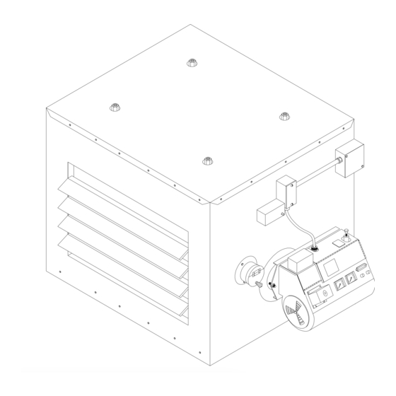
(2) Installing the Fan Assembly (3) Installing the Burner Clean Burn recommends that you review all assembly procedures before proceeding, paying careful attention to safety information statements. Figures 3A and 3B provide a general overview of the furnace components and their proper assembly and how the unit should look following proper assembly. -
Page 22: Installing The Observation Port
Operator's Manual: Model CB-1400 Installing the Observation Port CAUTION: To prevent serious personal injury, the observation port must be correctly installed according to the following procedure. A properly installed observation port permits safe obser- vation of the flame during furnace operation. Be sure to follow all safety procedures as outlined in this manual when observing the flame through the port. -
Page 23: Installing The Fan Assembly
Operator's Manual: Model CB-1400 Installing the Fan Assembly CAUTION: Ducting the CB-1400 Furnace is not permitted; it is intended for use as a Unit Heater ONLY. Refer to Figure 3C. Spin the fan blade to check that it spins freely. -
Page 24: Installing The Burner
Operator's Manual: Model CB-1400 Installing the Burner Checking the Burner Nozzle and Electrodes NOTE: The burner nozzle, a Delavan 9-5, is factory installed. The nozzle size is indicated on the nozzle as shown in Figure 3D. Refer also to Appendix A at the back of the manual for additional specifications/instructions on the burner nozzle. -
Page 25: Mounting The Burner On The Hinge Bracket
Operator's Manual: Model CB-1400 Installing the Burner (continued) Mounting the Burner on the Hinge Bracket ATTENTION: Burner tube components (e.g. electrodes and retention head) are factory set. Handle the burner with extreme care so that burner components are not damaged. -
Page 26: Installing The Connector Block, Oil Line Tubing, And Air Line Tubing
Operator's Manual: Model CB-1400 Installing the Connector Block, Oil Line Tubing, and Air Line Tubing Installing the Connector Block Refer to Figure 3F. SWIVEL ASSEMBLY Install the mounting bracket on the furnace cabinet MOUNTING BRACKET using the two (2) bolts supplied. -
Page 27: Installing The Air Line Tubing
Operator's Manual: Model CB-1400 Installing the Connector Block, Oil Line Tubing, and Air Line Tubing (continued) OIL LINE Installing the Oil Line Tubing (continued) OIL FITTING ON BURNER Make sure that the curl in the oil line is positioned as shown in Figure 3L so that the burner can swing open correctly. -
Page 28: Locking The Burner Into Firing Position
Operator's Manual: Model CB-1400 Installing the Connector Block, Oil Line Tubing, and Air Line Tubing (continued) AIR LINE FITTING ON BURNER OIL LINE FITTING ON BURNER AIR LINE OIL LINE COMPRESSION/ SWIVEL FITTING CONNECTOR BLOCK INSTALLED ON FURNACE CABINET Figure 3H - Installation of Connector Block, Oil Line, and Air Line (Front View) Locking the Burner into Firing Position Swing the burner into firing position. -
Page 29: Section 4: Furnace Installation
Likewise, the installation, operation, and maintenance of this equipment in Canada is to be accomplished by qualified personnel and in compliance with the specifications in the Clean Burn Operator's Manual and in accordance with the regulation of authorities having jurisdiction and the following CSA Standards:... - Page 30 Operator's Manual: Model CB-1400 WARNING: When installing your furnace, adhere to the minimum clearances from combustible surfaces as stated in Section 4. These clearances also provide adequate space for servicing. Failure to maintain proper clearances may result in fire, explosion, personal injury, or death.
-
Page 31: Selecting A Location
Operator's Manual: Model CB-1400 Selecting a Location Guidelines for Selecting a Location The location you select for your furnace must allow the following: • Unobstructed, even heat distribution. • Safe, easy access for servicing. • Unobstructed passage for shop vehicles and equipment. -
Page 32: Mounting The Furnace
Operator's Manual: Model CB-1400 Mounting the Furnace After selecting a safe and appropriate location for your furnace, construct the mounting system as required by the location and the following specifications. Ceiling Mounting WARNING: To prevent serious personal injury, ensure that your furnace mounting system can safely bear the suspended weight of the furnace and allow safe servicing of furnace components. -
Page 33: Raised Platform Mounting
• Add 12" (minimum) to all sides of the cabinet to achieve the total measurement for the non-combustible floor. The CB-1400 is approximately 34" x 30" 34" + 12" + 12" = 58" 30" + 12" + 12" = 54"... - Page 34 Operator's Manual: Model CB-1400 Constructing a Non-Combustible Floor (continued) Place a 24-gauge sheet metal pan with a 1" containment lip on top of the masonry blocks. This will provide containment of any oil that may be spilled while working on the furnace.
-
Page 35: Oil Tank Installation Specifications
The tank safety label (shown at right) also summarizes these important specifications for tank installation and usage. If you do not have a copy of this label, please contact your Clean Burn dealer for a copy, which is to be affixed directly to your used oil supply tank. •... -
Page 36: Installing The Tank Vent And Emergency Vent
National codes require that you install a tank vent (to the outside) and an emergency vent for your tank as shown in Figure 4F. Tank Vent Kits are available from Clean Burn; contact your local Clean Burn dealer to order. Be sure to check your local codes for any additional tank installation requirements, and adhere to the following installation guidelines: •... -
Page 37: Installing The Metering Pump
Operator's Manual: Model CB-1400 Installing the Metering Pump Preparing for Installation Before starting installation of the metering pump, review Figure 4G, 4H, and 4I to become familiar with the metering pump components. You will also need to accomplish the following activities: •... - Page 38 Operator's Manual: Model CB-1400 PART # DESCRIPTION 33363 CAPACITOR − GEARMOTOR see chart GEARMOTOR 11322 MOUNT − METER PUMP 32062 MALE CONNECTOR 1/4" T TO 1/4" NPT 32293 RELIEF VALVE 32425 1/4" NPT BRASS TEE 32424 LOW FLOW CHECK VALVE 32335 ADAPTOR PIPE 1/4"F X 1/8"M...
-
Page 39: Alternate Mounting: Horizontal Positioning
Operator's Manual: Model CB-1400 Installing the Metering Pump (continued) Alternate Mounting: Horizontal Positioning ATTENTION: If the metering pump is to be mounted horizontally or on a bracket as shown in Figure 4I, the pump head must be rotated counterclockwise so that it is aligned in a horizontal position. The gauge arrow on the pump head must point up, or the pump will not prime. -
Page 40: Wiring The Furnace And Pump
Operator's Manual: Model CB-1400 Wiring the Furnace and Pump WARNING: To avoid electrical shock, make sure that power to the furnace is turned OFF before connecting any wires. A licensed electrician should install all wiring to your furnace. All wiring must be in accordance with the National Uniform Electrical Code and local codes. -
Page 41: Installing The Suction Oil Line Components
Operator's Manual: Model CB-1400 Installing the Suction Oil Line Components ATTENTION: It is critical that you adhere to the following specifications for suction oil line installation (oil line from the tank to the pump). If these specifications are not met, the metering pump will not function correctly and the burner will shut down on reset. - Page 42 Operator's Manual: Model CB-1400 Installing the Suction Oil Line Components (continued) (1.) (e.) Prepare the canister filter for installation (continued): • Remove the plug from one of the 1/8" gauge ports in the canister filter and install the vacuum gauge. Seal the threads of the gauge with Permatex #2 non-hardening gasket sealer.
- Page 43 Operator's Manual: Model CB-1400 Install the suction oil line (from the the tank to the canister filter): a. Refer to Figures 4H and 4J. Prepare a piece of 1/2" O.D. copper tubing (user-supplied) which will function as the pick-up line from the tank to the canister filter. This copper tubing must have the following specifications: •...
-
Page 44: Installing The Pressure Relief And Low-Flow Check Valve
Operator's Manual: Model CB-1400 Installing the Pressure Relief and Low-Flow Check Valve ATTENTION: It is critical that you adhere to the following specifications for pressure relief and low-flow check valve installation; if these specifications are not met, the metering pump will not function correctly and the burner will shut down on reset. -
Page 45: Installing The Pressure Oil Line Components
50 psi and water trap or dryer. If you do not have shop air, an optional air compressor is available. Contact your local Clean Burn dealer for more information. Run a compressed air line from your shop air to the connector block on the furnace. Use minimum 1/4"... -
Page 46: Installing The Stack
Installing the Stack WARNING: Inappropriate stack materials or improper stack design/installation can adversely affect the proper, safe operation of your furnace. Contact your Clean Burn dealer to purchase the proper stack components for your furnace. Stack designs are generally classified as follows: (1) "Class A"... - Page 47 Operator's Manual: Model CB-1400 Installing the Stack (continued) "CLASS A" STACK CAP − NON−RESTRICTIVE TYPE TO ALLOW FREE FLOW OF THE STACK GASES NOTE: THE LAST STACK SECTION SHALL EXTEND AT LEAST WARNING! ENSURE PROPER 3 FEET ABOVE THE HIGHEST POINT AT WHICH IT COMES IN...
- Page 48 Operator's Manual: Model CB-1400 Installing the Stack (continued) "CLASS A" STACK CAP − NON−RESTRICTIVE TYPE TO ALLOW FREE FLOW OF THE STACK GASES WARNING! ENSURE PROPER CLEARANCES BETWEEN STACK COMPONENTS AND COMBUSTIBLES PER ALL APPLICABLE CODES. NOTE: THE LAST STACK SECTION SHALL EXTEND AT LEAST...
-
Page 49: Installing The Interior Stack
Operator's Manual: Model CB-1400 Installing the Interior Stack WARNING: Single wall stack components may be used only for those portions of the stack which are located inside your building and away from any fire/burn hazards. Install the single wall stack with proper clearances from combustibles. Also ensure that the stack is located a safe distance from all shop personnel. -
Page 50: Installing The Stack Safety Switch For Canadian Installations
Operator's Manual: Model CB-1400 Installing the Stack Safety Switch For Canadian Installations NOTE: CSA Standards require that all heating equipment must be installed with a stack safety switch. If your heating equipment is being installed in Canada, follow the instructions listed below. -
Page 51: Resetting The Stack Safety Switch
Operator's Manual: Model CB-1400 Resetting the Stack Safety Switch WARNING: BURN HAZARD! To prevent serious personal injury, be sure to allow ample time, at least 30 minutes, for the stack, barometric damper, and switch to cool down before attempting to access and service these components. -
Page 52: Installing The Stack Penetration
ATTENTION: The draft inducer, Field brand model DI-2, is optional equipment and may be installed to ensure proper draft. The Field brand draft inducer has been tested for use on Clean Burn furnaces. DO NOT use other models or brands of draft inducers. - Page 53 Operator's Manual: Model CB-1400 Installing the Optional Draft Inducer (continued) Installing the Draft Inducer WARNING: Turn OFF the main power to the furnace before proceeding with the installation of the draft inducer. ATTENTION: It is very important to install the draft inducer on a vertical section of stack to isolate the inducer from excessive heat and ash buildup.
-
Page 54: Installing The Wall Thermostat
Operator's Manual: Model CB-1400 Installing the Optional Draft Inducer (continued) Wiring the Draft Inducer for Normal Operation* *(No exhaust fans in the building. Read pages 8-3 to 8-6 if exhaust fans are present.) Wire the draft inducer according to the Furnace Wiring Diagram provided in Appendix B at the back of this manual. -
Page 55: Section 5: Metering Pump Priming
Operator's Manual: Model CB-1400 SECTION 5: METERING PUMP PRIMING Understanding Metering Pump Priming Preparing your Clean Burn furnace for operation begins with priming the metering pump. The procedures in this section must be performed in sequence without interruption to properly prime the pump. -
Page 56: Preparing The Burner For Use With The Metering Pump
Operator's Manual: Model CB-1400 Preparing the Burner for Use with the Metering Pump WARNING: To avoid electrical shock hazards, turn off all power to the furnace, and unplug the burner before proceeding. Figure 5A shows an exterior view of the burner components. In this procedure, you will be removing the oil regulator from the preheater block assembly to prepare the burner for use with the metering pump. - Page 57 Operator's Manual: Model CB-1400 SAVE AND USE THESE 4 SCREWS AND WASHERS TO INSTALL SQUARE CAP STEP 1 SURFACE MOUNTED REMOVE OIL REGULATOR THESE PARTS (COMPLETE REGULATOR) STEP 2 INSTALL SQUARE CAP AND "O" RING I88193 Figure 5B - Detail of Heater Block with Surface-Mounted Oil Regulator...
-
Page 58: Priming The Metering Pump
Operator's Manual: Model CB-1400 Priming the Metering Pump ATTENTION: The priming process must be done precisely as described in this procedure to ensure that all air is thoroughly bled from the system. Failure to bleed all air from the system will result in repeated burner shutdowns on reset. - Page 59 Operator's Manual: Model CB-1400 Priming the Metering Pump (continued) Activating the Pump WARNING: Activating the pump for pump priming involves running the burner by jumping the "F" terminals of the oil primary control. This procedure (i.e. jumping the "F" terminals) should be used only for this specific purpose--never for normal operation. This procedure is accomplished easily by two people: one at the burner and one at the wall thermostat.
-
Page 60: Vacuum Testing The Oil Pump
Operator's Manual: Model CB-1400 Priming the Metering Pump (continued) Run the pump until a solid stream of oil flows from the pump bleeder. This will bleed all air out of the suction line, oil filter and pump head. ATTENTION: For the metering pump to operate correctly, it is very important that the system is entirely full of oil and all air is bled out. - Page 61 Operator's Manual: Model CB-1400 Vacuum Testing the Oil Pump (continued) The vacuum should increase within 15 seconds to 15 inches of vacuum. When the vacuum gauge reads 15 inches of vacuum, first close and tighten the bleeder, then turn the pump off.
- Page 62 Operator's Manual: Model CB-1400...
-
Page 63: Section 6: Starting And Adjusting The Burner
Operator's Manual: Model CB-1400 SECTION 6: STARTING AND ADJUSTING THE BURNER Understanding Burner Startup and Adjustment Starting and adjusting the burner involves a series of separate procedures which must be accomplished in sequence without interruption. Review all the procedures before attempting burner startup and adjustment, paying careful attention to safety information statements. - Page 64 Used Hydraulic Oil* check flame length 12-16 1/4" #4 and #5 Fuel Oils check flame length 12-16 1/4" *If you are burning light viscosity oils, it may be necessary to install a smaller nozzle. Call your Clean Burn dealer for more information.
-
Page 65: Starting The Burner
Operator's Manual: Model CB-1400 Starting the Burner Adjust the thermostat setting above room temperature to start the burner. Adjusting the Air Regulator: As soon as the burner starts running, turn the knob on the air regulator clockwise to achieve proper operating air pressure. Refer to the Initial Adjustment Charts. -
Page 66: Checking The Operation Of The Fan Motor
The fan limit control will then shut off the motor. WARNING: If the fan motor does not operate as described, immediately shut down your furnace to avoid potential equipment damage and/or fire hazard. Contact your Clean Burn dealer immediately. -
Page 67: Section 7: Resetting The Oil Primary Control
SECTION 7: RESETTING THE OIL PRIMARY CONTROL Understanding the Oil Primary Control NOTE: The CB-1400 primary controller (CB Part #33400) is a recycle type control, which features interrupted ignition operation. The oil primary control will go into safety lockout and shut the burner off when it detects flame-out during burner operation. - Page 68 Operator's Manual: Model CB-1400...
-
Page 69: Section 8: Adjusting The Draft Overfire
A qualified serviceman with proper equipment must check/adjust your furnace for proper draft. Contact your Clean Burn dealer for this service. Insert the probe of the draft gauge instrument into the draft reading port in the observation port as shown in Figure 8A. -
Page 70: Adjusting The Barometric Damper
Solving Draft Overfire Problems WARNING! If you cannot achieve proper draft overfire, do not operate your furnace! Contact your Clean Burn dealer for assistance. ATTENTION: Backdraft must be resolved or your furnace will not operate correctly! Under backdraft conditions, draft overfire readings will show positive pressure in the combustion chamber. -
Page 71: Understanding The Effect Of Exhaust Fans On Draft
Operator's Manual: Model CB-1400 Understanding the Effect of Exhaust Fans on Draft Any type of exhaust fan, paint booth, or exhaust system in a building will create negative pressure in the building unless there is a source of make-up air (i.e. fresh air which enters the building and replaces the air removed by the exhaust fans.) Refer to Figure 8C. - Page 72 Operator's Manual: Model CB-1400 BACKDRAFT EXHUST FAN CREATES BACKDRAFT IN STACK AND SUCKS COMBUSTION GASES DOWN THE STACK AND BACK INTO THE FURNACE To arrive at proper draft measurements be sure that all fans within the building are running while...
-
Page 73: Installing A Make-Up Air Louver
Operator's Manual: Model CB-1400 Installing a Make-up Air Louver Exhaust Fans and Make-up Air Louvers When exhaust fans are operated in tight buildings, there is little or no source of fresh air to replace the air removed from the building by the exhaust fan. This results in negative pressure (vacuum) in the building which creates severe backdraft problems at the furnace. - Page 74 Operator's Manual: Model CB-1400 Installing a Make-up Air Louver (continued) Calculated Opening Size Required Louver / Grill Size (Square Feet) (Inches) From 0.000 to 0.569 10 x 10 From 0.570 to 0.900 12 x 12 From 0.901 to 1.556 16 x 16 From 1.557 to 2.070...
-
Page 75: Section 9: Maintenance
SECTION 9: MAINTENANCE Understanding Maintenance Servicing your Clean Burn furnace in a timely manner is very important to keep your furnace running in peak condition. Just as an automobile requires periodic maintenance such as oil changes, engine tune-ups, etc. your Clean Burn furnace also requires regularly scheduled service. -
Page 76: Periodic Burner Inspection
Operator's Manual: Model CB-1400 Periodic Burner Inspection Following initial start up of the burner, you should inspect the operation of the burner periodically--ideally on a monthly basis. Doing so ensures that the system is functioning efficiently and safely. Follow these guidelines for inspecting the operation of the burner: •... -
Page 77: Cleaning The Canister Filter
Operator's Manual: Model CB-1400 Cleaning the Canister Filter ATTENTION: Never operate your furnace with more than 10" HG of vacuum on the suction side of the pump. High vacuum separates air from the oil and results in erratic burner operation. -
Page 78: Servicing The Metering Pump
Remove the pump head cover (part 1). Remove the screen (part 2) and wash it. Remove and discard the used gasket (part 3). Install a new gasket (Clean Burn Part #32422). Replace the screen and pump head cover. Figure 9C - Servicing the Metering Pump... -
Page 79: Cleaning The Check Valve And Check Valve Screen
Operator's Manual: Model CB-1400 Cleaning the Check Valve And Check Valve Screen This procedure applies to furnace installations with inside and outside tanks. The following protective gear should be worn when cleaning the check valve/screen: • Rubber gloves • Safety goggles Refer to Figure 9D. -
Page 80: Cleaning The Tank
Operator's Manual: Model CB-1400 Cleaning the Tank DO NOT allow water, sludge, or other debris to accumulate in your oil supply tank to the point that non- combustible or harmful materials are drawn into the pump or burner. Drain water and sludge from the bottom of your tank at least once a year, and more frequently with water accumulation. - Page 81 Operator's Manual: Model CB-1400 Cleaning Ash from the Furnace (continued) Figure 9E - Accessing the Combustion Chamber for Cleaning Ensure that power has been turned OFF, and all "hot" components have been allowed to cool sufficiently. Allow at least one hour for the target to cool.
- Page 82 ATTENTION: White ash indicates excessive air pressure. Black ash or soot indicates lack of combustion air. If these conditions exist, call your Clean Burn dealer. DO NOT overfire your furnace by turning up the compressed air pressure. Overfiring will damage the combustion chamber and heat exchanger and will void your warranty.
-
Page 83: Annual Burner Tune-Up
Contact your local Clean Burn dealer to schedule your annual burner tune-up. Allow only trained, authorized service personnel to service your burner. - Page 84 Operator's Manual: Model CB-1400 9-10...
-
Page 85: Section 10: Troubleshooting
Operator's Manual: Model CB-1400 SECTION 10: TROUBLESHOOTING The following charts and tables are provided for reference in troubleshooting any difficulties encountered in furnace operation and adjustment. • The Flow Chart outlines the proper sequence of events in furnace operation -- use this chart to help diagnose where a problem may be occurring. - Page 86 Operator's Manual: Model CB-1400 10-2...
-
Page 87: Troubleshooting Tables
Operator's Manual: Model CB-1400 Troubleshooting Tables PROBLEM POSSIBLE CAUSE POSSIBLE ACTION(S) Burner won’t run at all and Circuit breaker/main switch open. Close circuit breaker/switch. Green power light is NOT ON. Fuse/breaker blown. Electrician should check out electrical system. Burner cable is damaged or not Check burner cable. - Page 88 Operator's Manual: Model CB-1400 Troubleshooting Tables (continued) PROBLEM POSSIBLE CAUSE POSSIBLE ACTION(S) Burner ignites, but will not stay running There is a fuel delivery problem. Follow the procedures listed in the and Burner shuts off on reset within 15 next problem.
- Page 89 Operator's Manual: Model CB-1400 Troubleshooting Tables (continued) PROBLEM POSSIBLE CAUSE POSSIBLE ACTION(S) Burner ignites and Burner shuts off on There is air in the fuel supply. Prime the pump. If the pump will reset sometime later during the day or not prime or there is air in the oil night.
- Page 90 Operator's Manual: Model CB-1400 Troubleshooting Tables (continued) PROBLEM POSSIBLE CAUSE POSSIBLE ACTION(S) Pump will not prime and Pump motor is There is a leak(s) in the suction Follow the specifications in Section 4 to make sure the running. line. suction line is installed properly and that all fittings are 100% airtight.
- Page 91 Section 6 to test for proper fan operation. If the fan does not operate, shut OFF power to the furnace and call your Clean Burn dealer for service. The Fan / Limit switch is Replace the Fan / Limit switch.
- Page 92 Operator's Manual: Model CB-1400 10-8...
-
Page 93: Detailed Furnace Specifications
Operator's Manual: Model CB-1400 APPENDIX A Detailed Furnace Specifications Furnace Technical Specifications SPECIFICATIONS CB-1400 BTUH Input 140,000 @ 1.0 GPH Listed Fuels #2, #4 Fuel Oils Used Crankcase Oil Used ATF Used Hydraulic Oil Cabinet Dimensions 33 ¾ x 29 ¾ x 29... -
Page 94: Burner Technical Specifications
Operator's Manual: Model CB-1400 Burner Technical Specifications Burner CB-525-S2 Ignition Transformer Carlin Transformer 14,000 Volts Nozzle Delavan 9-5 Burner Motor 1/10 HP 3200 RPM with centrifugal switch Burner Motor Rotation CCW shaft end Compressed Air Requirements 2.0 CFM @ 50 PSI... -
Page 95: Furnace Dimensions
Operator's Manual: Model CB-1400 Furnace Dimensions 16 7/8" 33 3/4" 20 7/8" 47 3/4" WITH BURNER INSTALLED TOP VIEW (SHOWING MOUNTING LUGS) 29 3/4" 23 1/8" 6 7/8" 29" 16 1/4" SIDE VIEW (LOUVER SIDE) FRONT VIEW (BURNER SIDE) 40"... -
Page 96: Burner Components
Operator's Manual: Model CB-1400 Burner Components (CB-525-S2) SEE ILLUSTRATION I88543 FOR PART NUMBERS CB − 525 − S2 BURNER I88234−B Figure A1 - CB-525-S2 Burner Component Detail... - Page 97 Operator's Manual: Model CB-1400 Burner Components (CB-525-S2) (continued) Item# Clean Burn Part# Qty. Component Description 26103 AIR INTAKE OUTER PLATE 11359 AIR INTAKE INNER PLATE 33188 CARLIN PRIMARY CONTROL 33335 ISOLATOR 33189 CARLIN IGNITER (TRANSFORMER) 33116 CAD CELL 11243 TRANSFORMER PLATE...
- Page 98 Operator's Manual: Model CB-1400 Burner Components (continued) I88543 Figure A2 - Preheater Block Assembly Component Detail...
- Page 99 Operator's Manual: Model CB-1400 Burner Components (continued) Item# C.B. Part# Qty. Component Description 34169 ELECTRODE SCREW - 10-32 x 3/4 33183 SINGLE PIECE ELECTRODE 34165 WASHER 32000 9 - 5 NOZZLE 13150 NOZZLE ADAPTOR 32007 PLUG - 1/8 NPT 33298...
- Page 100 Operator's Manual: Model CB-1400 Burner Components (continued) INSTALLATION OF THE SPINNER RETENTION HEAD THE SPINNER RETENTION HEAD FITS INSIDE THE BURNER TUBE AND REQUIRES (3) SELF−TAPPING SCREWS. IT IS VERY IMPORTANT THAT THE SPINNER HEAD IS NOT TIPPED FROM SIDE TO SIDE OR FROM TOP TO BOTTOM.
-
Page 101: Cleaning The Nozzle
Check the electrodes for proper gap and clearances. (Figure A3) Re-install the burner and adjust for optimal performance as described in Section 6. NOTE: If the nozzle plugs within a few days after cleaning, call your Clean Burn Dealer for service. -
Page 102: Fan Limit Control
LINE the desired setting. ATTENTION: DO NOT rotate the dial when setting the pointers. This severely damages the control. Fan Limit Control Settings: CB-1400 Fan Off: BRASS JUMPER BLACK WIRE Fan On: I88840... -
Page 103: Wiring Diagrams
Operator's Manual: Model CB-1400 APPENDIX B Wiring Diagrams 120 VOLTS, 60 Hz, SINGLE PHASE BLACK BLACK WHITE WHITE CIRC. FAN MOTOR BLACK WHITE OIL PUMP BLACK BLACK DRAFT INDUCER WHITE FAN (OPTIONAL) PURPLE ORANGE GREEN GROUND WHITE SCREW ORANGE GREEN... -
Page 104: Burner Wiring Diagram
Operator's Manual: Model CB-1400 Wiring Diagrams (continued) FIGURE B2 - Burner Wiring Diagram... - Page 105 Operator's Manual: Model CB-1400 OPTIONAL SERVICE DISCONNECT SWITCH NEUTRAL CIRC FAN MOTOR FAN LIMIT CONTROL SEE OPERATOR'S HI LIMIT MANUAL OIL PUMP MOTOR DRAFT INDUCER MOTOR (OPTIONAL) WALL THERMOSTAT CELL PROVING SWITCH 120° PRIMARY CONTROL AIR COMPRESSOR (OPTIONAL) AIR SOL.
-
Page 106: Metering Pump Wiring Schematic
Operator's Manual: Model CB-1400 Wiring Diagrams (continued) H44040 Figure B4 - Metering Pump Wiring Schematic... -
Page 107: Furnace Service Record
Operator's Manual: Model CB-1400 APPENDIX C Furnace Service Record Furnace Purchased: Date __________ From (name/phone)________________________________ Furnace Installed: Date ___________ By (name/phone)__________________________________ Furnace Inspected: Date __________ By (name/phone)__________________________________ Draft Readings Service Record (date / reading) (date / initials of serviceman) Burner... - Page 108 Operator's Manual: Model CB-1400...
Need help?
Do you have a question about the CB-1400 and is the answer not in the manual?
Questions and answers