Table of Contents
Advertisement
Quick Links
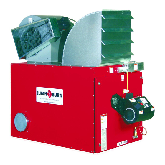
CLEAN BURN MULTI-OIL FURNACE MODELS:
CB-3500 and CB-5000 with CB-500 Series BURNER
230 V / 50 Hz
FOR YOUR SAFETY −
DO NOT STORE GASOLINE
OR OTHER FLAMMABLE VAPORS AND LIQUIDS
IN THE VICINITY OF THIS OR ANY APPLIANCE!!
PUBLICATION DATE: 2/15/07, Rev. 10
WARNING: DO NOT assemble, install, operate, or maintain this equipment without first
reading and understanding the information provided in this manual. Installation and
service must be accomplished by qualified personnel. Failure to follow all safety precautions
and procedures as stated in this manual may result in property damage, serious personal injury
or death.
CLEAN BURN, INC. • 34 Zimmerman Road • Leola, PA 17540 • U.S.A.
The Clean Burn logo is a trademark of Clean Burn, Inc. All other brand or product names mentioned are the registered
trademarks or trademarks of their respective owners.
Copyright © 2007 Clean Burn, Inc. All rights reserved. No part of this publication may be reproduced, or distributed without
the prior written permission of Clean Burn, Inc. 34 Zimmerman Road, Leola, PA 17540. Subject to change without notice.
OPERATOR'S MANUAL
I88911
CLEAN BURN PART #43143
Advertisement
Table of Contents

Related Manuals for CLEAN BURN CB-3500 series


Summary of Contents for CLEAN BURN CB-3500 series
- Page 1 CLEAN BURN, INC. • 34 Zimmerman Road • Leola, PA 17540 • U.S.A. The Clean Burn logo is a trademark of Clean Burn, Inc. All other brand or product names mentioned are the registered trademarks or trademarks of their respective owners.
-
Page 3: Table Of Contents
TABLE OF CONTENTS SECTION 1: INTRODUCTION ................... 1-1 Guide to this Manual ......................1-1 For Your Safety......................... 1-2 Guidelines for Furnace Usage ..................1-4 Guidelines for Used Oil Tanks ..................1-5 Safety Labels ......................1-6 SECTION 2: UNPACKING ..................2-1 Removing the Shipping Crate .................. - Page 4 TABLE OF CONTENTS SECTION 4: FURNACE INSTALLATION ..............4-1 Understanding Installation ....................4-1 Important Safety Guidelines for Safe Installation ............4-1 Important Notes to the Electrician ................4-2 Selecting a Location ......................4-4 Guidelines for Selecting a Location ................4-4 Mounting the Furnace ......................
- Page 5 TABLE OF CONTENTS SECTION 7: RESETTING THE FURNACE AND BURNER ........7-1 Understanding Furnace/Burner Shutdowns ................7-1 The Oil Primary Control ..................... 7-1 Resetting the Oil Primary Control ................. 7-1 Understanding the Fan Switches and Hi-Limits ..............7-2 The Blower/Fan Switch ...................... 7-2 The Fan Limit Control ......................
- Page 6 TABLE OF CONTENTS APPENDIX B Wiring Diagrams ....................... B-1 Furnace Wiring Diagram ..................... B-1 Burner Wiring Diagram ....................B-2 Ladder Schematic ...................... B-3 Metering Pump Wiring Schematic ................B-4 APPENDIX C Additional Requirements for the United Kingdom ............... C-1 APPENDIX D Furnace Service Record ....................
-
Page 7: Section 1: Introduction
You'll find this manual's step-by-step procedures easy to follow and understand. Should questions arise, please contact your Clean Burn dealer before starting any of the procedures in this manual. As you follow the directions in this manual, you'll discover that assembling and operating your new furnace involves six basic activities as outlined here: •... -
Page 8: For Your Safety
Operator's Manual: Models CB-3500 and CB-5000 (230 V / 50 Hz) For Your Safety... For your safety, Clean Burn documentation contains the following types of safety statements (listed here in order of increasing intensity): • NOTE: A clarification of previous information or additional pertinent information. - Page 9 Clean Burn, Inc. Unauthorized modifications or alteration can adversely affect the proper, safe operation of your furnace. WARNING: The burner which is shipped with your Clean Burn furnace is to be used only with your furnace according to the instructions provided in this manual. DO NOT use the...
-
Page 10: Guidelines For Furnace Usage
Contact your Clean Burn dealer for current environmental regulations. • If your furnace ever requires service, call your Clean Burn dealer. DO NOT allow untrained, unauthorized personnel to service your furnace. Make sure that your furnace receives annual preventative maintenance to ensure optimal performance. -
Page 11: Guidelines For Used Oil Tanks
DO NOT use it. • If you do not have a copy of the tank safety label pictured at right, please contact your Clean Burn dealer for the label, which is to be affixed directly on your used oil supply tank. -
Page 12: Safety Labels
(e.g. ATTENTION, CAUTION, WARNING, DANGER). For your safety and the safe operation of your furnace, review all labels and heed all safety messages as printed on the labels. If any labels on your Clean Burn furnace ever become worn, lost or painted over, please call your Clean Burn dealer for free replacements. - Page 13 Operator's Manual: Models CB-3500 and CB-5000 (230 V / 50 Hz) For Your Safety... (continued) CB-3500/CB-5000 Furnace Cabinet Safety Labels...
- Page 14 Operator's Manual: Models CB-3500 and CB-5000 (230 V / 50 Hz) For Your Safety... (continued) CB-3500 / CB-5000 Furnace Cabinet Safety Labels (continued) LEOLA, PENNSYLVANIA (USA) LEOLA, PENNSYLVANIA (USA) LABEL SERIAL NO. LABEL SERIAL NO. MULT−OIL BURNING UNIT HEATER MULT−OIL BURNING UNIT HEATER WHEN USED WITH THE FOLLOWING WHEN USED WITH THE FOLLOWING LISTED FUELS...
- Page 15 Operator's Manual: Models CB-3500 and CB-5000 (230 V / 50 Hz) For Your Safety... (continued) CB-3500 / CB-5000 Burner Labels Label Part # Description 42005 Sold and Serviced By Label 42004 Burner Safety Warning Label 42004 42197 (High Voltage/Moving Parts Hazards) Danfoss 220−240V 50−60Hz 3W 42339/...
- Page 16 Operator's Manual: Models CB-3500 and CB-5000 (230 V / 50 Hz) 1-10...
-
Page 17: Section 2: Unpacking
Model CB-3500; it will require additional installation for Model CB-5000.) Unpacking and Inspecting All Components Following is an itemized list of all components you should have received in your Clean Burn furnace shipment. Open all shipping containers and inspect all components according to the list. Immediately notify the freight company and your Clean Burn dealer in case of shipping damage or shortage(s). -
Page 18: Unpacking Items Packed Inside The Furnace
Operator's Manual: Models CB-3500 and CB-5000 (230 V / 50 Hz) Unpacking Items Packed Inside the Furnace To unpack the items packed inside the furnace cabinet (in the combustion chamber), you will need to open the combustion chamber door. Remove the four nuts and washers which hold the combustion chamber door closed. Set the nuts and washers aside in a safe place for later re-installation after the target has been installed (Section 3). -
Page 19: Section 3: Furnace Assembly
(5) Installing the Connector Block, Oil Line Tubing, and Air Line Tubing (6) Installing the Mounting and Stabilizer Brackets Clean Burn recommends that you review all assembly procedures before proceeding, paying careful attention to safety information statements. Please note that some assembly procedures apply only to certain furnace models. - Page 20 Operator's Manual: Models CB-3500 and CB-5000 (230 V / 50 Hz) ’ALL THREAD’ ROD STABILIZER BRACKET ON TOP OF FURNACE AIR DISCHARGE JUNCTION BOX FAN LIMIT BURNER CABLE BURNER MOUNT 2 20 -2 40V 50-60Hz 3W Danfoss ts 10s T y pe B HO 64 N r.
- Page 21 Operator's Manual: Models CB-3500 and CB-5000 (230 V / 50 Hz) STABILIZER BRACKETS MOUNTING BRACKETS I88915 Figure 3B - Three-dimensional View - Furnace Completely Assembled with Louver Assembled for Unit Heater Application NOTE: This figure shows the mounting/stabilizer brackets in place for a ceiling mounted installation. If your furnace will be floor or platform mounted, the brackets are not needed.
-
Page 22: Installing The Blower Components
Operator's Manual: Models CB-3500 and CB-5000 (230 V / 50 Hz) Installing the Blower Components NOTE: The blower is installed in final position on the CB-3500 cabinet. The blower for the CB-5000 requires additional installation as described in the following procedure. Installing the Blower (Model CB-5000 ONLY) NOTE: For proper air flow through the furnace, the blower must be positioned so the bulge on the blower faces toward the rear of the furnace as illustrated in Figures 3A, 3B, and 3D. - Page 23 Operator's Manual: Models CB-3500 and CB-5000 (230 V / 50 Hz) B LOWER ASSEMBLY PARTS LIST 2 HP MOTOR MOTOR PULLEY MOTOR MOUNTING PLATE BOLT MOTOR TENSIONING BRACKET BLOWER PULLEY SELF−TAPPING BOLT 10 V−BELT 11 MOTOR MOUNTING BRACKET 12 SQUARE HEAD BOLT CB−3500 BLOWER CB−5000 BLOWER DETAIL OF BRACKET INSTALLATION...
-
Page 24: Installing The Motor Pulley, Blower Pulley, And V-Belt
Operator's Manual: Models CB-3500 and CB-5000 (230 V / 50 Hz) Installing the Blower Components (continued) Installing the Motor Pulley, Blower Pulley, and V-Belt Refer to Figures 3C and 3D. Slide the pulleys into position on the motor and blower shafts. ATTENTION: Make sure that the face of the motor is flush with the side of the blower. -
Page 25: Installing The Belt Guard And The Blower Guard
Operator's Manual: Models CB-3500 and CB-5000 (230 V / 50 Hz) Installing the Belt Guard and the BLOWER GUARD Blower Guard WARNING: To prevent serious personal injury, DO NOT operate the furnace without the belt and blower guards in place. BELT GUARD Refer to Figure 3E. -
Page 26: Installing The Hot Air Discharge Components
Operator's Manual: Models CB-3500 and CB-5000 (230 V / 50 Hz) Installing the Hot Air Discharge Components Determining the Air Discharge Configuration The CB-3500 and CB-5000 furnaces may be configured for use as EITHER a Unit Heater or a Central Furnace as described below. -
Page 27: Unit Heaters: Installing The Air Discharge Louver Assembly
Operator's Manual: Models CB-3500 and CB-5000 (230 V / 50 Hz) UNIT HEATER APPLICATIONS: Installing the Air Discharge Louver Assembly The body of the air discharge louver assembly is shipped assembled and is packed on top of the furnace cabinet. The louvers, nuts and bolts, which must be assembled separately, are packed inside the combustion chamber. -
Page 28: Central Furnaces: Installing Ductwork
Operator's Manual: Models CB-3500 and CB-5000 (230 V / 50 Hz) CENTRAL FURNACE APPLICATIONS: Installing Ductwork If you plan to install ductwork on your furnace, it is mandatory that qualified HVAC personnel design and install the ductwork system to the Air Flow and SP specifications provided in this manual. Establish correct duct size according to the following specifications and use radial bends or turning vanes to allow for proper air flow. -
Page 29: Installing The Burner
Operator's Manual: Models CB-3500 and CB-5000 (230 V / 50 Hz) Installing the Burner Checking the Burner Nozzle and Electrodes NOTE: The burner nozzle is factory installed. Model CB-3500 uses a Delavan 9-5 nozzle. Model CB-5000 uses a Delavan 9-11 nozzle. The nozzle size is indicated on the nozzle head as shown in Figure 3G. -
Page 30: Mounting The Burner On The Hinge Bracket
Operator's Manual: Models CB-3500 and CB-5000 (230 V / 50 Hz) Installing the Burner (continued) Mounting the Burner on the Hinge Bracket ATTENTION: Burner tube components (e.g. electrodes and retention head) are factory set. Handle the burner with extreme care so that burner components are not damaged. Remove the nut from the mounting flange of the furnace cabinet, and set it aside for later use. -
Page 31: Installing The Connector Block, Oil Line Tubing, And Air Line Tubing
Operator's Manual: Models CB-3500 and CB-5000 (230 V / 50 Hz) Installing the Connector Block, Oil Line Tubing, and Air Line Tubing ATTENTION: DO NOT use teflon tape on any fittings. Teflon tape will plug vital burner components. Installing the Connector Block on the Furnace Door OIL LINE Refer to Figure 3H. -
Page 32: Installing The Air Line Tubing
Operator's Manual: Models CB-3500 and CB-5000 (230 V / 50 Hz) Installing the Connector Block, Oil Line Tubing, and Air Line Tubing (continued) Installing the Oil Line Tubing (continued) Make sure that the curl in the oil line is positioned as shown in Figure 3H so that the burner can swing open correctly. -
Page 33: Locking The Burner Into Firing Position
Operator's Manual: Models CB-3500 and CB-5000 (230 V / 50 Hz) Locking the Burner into Firing Position Swing the burner into firing position. Install and tighten the lock-down nut on the mounting plate bolt to secure the burner in its firing position. PLUG ON CAM Plug the burner electrical cable into the receptacle on the LOCK CABLE... - Page 34 Operator's Manual: Models CB-3500 and CB-5000 (230 V / 50 Hz) 3-16...
-
Page 35: Section 4: Furnace Installation
(9) Installing the Wall Thermostat (10) Inspecting the Installation Clean Burn recommends that you review all procedures before beginning installation, paying careful attention to safety information statements. Figures 4A provides a general overview of a typical furnace installation and should be reviewed closely before proceeding. -
Page 36: Important Notes To The Electrician
WARNING: Low voltage terminals are only protected by basic insulation--caution is required. CAUTION: Use only approved wire conduit and connectors when wiring the Clean Burn furnace. An emergency stop device (i.e. "panic button") must be installed at ground level in the mains cable to the furnace to ensure the safety of furnace operators and service personnel. - Page 37 Operator's Manual: Models CB-3500 & CB-5000 (230 V / 50 Hz) WARNING: When installing your furnace, adhere to the minimum clearances from combustible surfaces as stated in Section 4. These clearances also provide adequate space for servicing. Failure to maintain NOTE: THE LAST STACK proper clearances may result in fire, SECTION SHALL EXTEND AT...
-
Page 38: Selecting A Location
Operator's Manual: Models CB-3500 & CB-5000 (230 V / 50 Hz) Selecting a Location Guidelines for Selecting a Location The location you select for your furnace must allow the following: • Unobstructed, even heat distribution. • Safe, easy access for servicing. •... -
Page 39: Mounting The Furnace
EXHAUST GASES RESULTING IN POOR BURNER PERFORMANCE AND BACK PRESSURE IN THE FURNACE WATERTIGHT ROOF FLASHING: WARNING: USE MINIMUM 64 mm x 64 mm CLEAN BURN RECOMMENDS "DEKTITE" (2−1/2" X 2−1/2") ANGLE IRON BEAMS, FLASHING FOR A WATERTIGHT SEAL BRIDGED ACROSS SUFFICIENT DOUBLE NUTS... -
Page 40: Raised Platform Mounting
Operator's Manual: Models CB-3500 & CB-5000 (230 V / 50 Hz) Mounting the Furnace (continued) Raised Platform Mounting WARNING: To prevent serious personal injury, make sure the platform is designed to safely bear the weight of the furnace and allow safe servicing of furnace components. - Page 41 Operator's Manual: Models CB-3500 & CB-5000 (230 V / 50 Hz) Constructing A Non-Combustible Floor (continued) Place a 24-gauge sheet metal pan with a 2.5 cm (1") containment lip on top of the masonry blocks. This will provide containment of any oil that may be spilled while working on the furnace. Position the furnace on top of the sheet metal pan;...
-
Page 42: Oil Tank Installation Specifications
Ensure that the oil supply tank is properly maintained; refer to Section 9 in this manual for related procedures. ATTENTION: For outside tank installations and/or tanks larger than 1890 Liters (500 gallons), contact the Clean Burn Service Department for installation recommendations and specifications. -
Page 43: Installing The Tank Vent And Emergency Vent
Codes require that you install a tank vent (to the outside) and an emergency vent for your tank as shown in Figure 4F. Tank Vent Kits are available from Clean Burn; contact your local Clean Burn dealer to order. Be sure to check your local codes for any additional tank installation requirements, and adhere to the following installation guidelines: •... -
Page 44: Installing The Metering Pump
Operator's Manual: Models CB-3500 & CB-5000 (230 V / 50 Hz) Installing the Metering Pump Preparing for Installation Before starting installation of the metering pump, review Figures 4G, 4H, and 4I to become familiar with the metering pump components. You will also need to accomplish the following activities: •... - Page 45 1/2" NPT x 1/2" TUBING SLIP ADAPTER 32442 2" x 1/2" x 1/2" NPT DUPLEX HEX BUSHING 32021 3/4" CHECK VALVE 32061 3/4" CHECK VALVE SCREEN 32445 1/2" PIPE CAP CLEAN BURN GEARMOTOR MODEL PART # CB−1502 33425 CB−2501 33426 CB−3500 33427 CB−5000...
-
Page 46: Alternate Mounting: Horizontal Positioning
Operator's Manual: Models CB-3500 & CB-5000 (230 V / 50 Hz) Installing the Metering Pump (continued) Alternate Mounting: Horizontal Positioning ATTENTION: If the metering pump is to be mounted horizontally or on a bracket as shown in Figure 4I, the pump head must be rotated counterclockwise so that it is aligned in a horizontal position. The gauge arrow on the pump head must point up, or the pump will not prime. -
Page 47: Wiring The Furnace And Pump
Operator's Manual: Models CB-3500 and CB-5000 (230 V / 50 Hz) Wiring the Furnace and Pump WARNING: To avoid electrical shock, make sure that power to the furnace is turned OFF before connecting any wires. A licensed electrician should install all wiring to your furnace. All wiring must be in accordance with the national and local codes. -
Page 48: Installing The Suction Oil Line Components
Operator's Manual: Models CB-3500 and CB-5000 (230 V / 50 Hz) Installing the Suction Oil Line Components ATTENTION: It is critical that you adhere to the following specifications for suction oil line installation (oil line from the tank to the pump). If these specifications are not met, the metering pump will not function correctly and the burner will shut down on reset. - Page 49 Operator's Manual: Models CB-3500 and CB-5000 (230 V / 50 Hz) Installing the Suction Oil Line Components (continued) (1.) (e.) Prepare the canister filter for installation (continued): • Install the 3/4" x 1/2" brass bushing into the inlet port of the canister filter. •...
- Page 50 Operator's Manual: Models CB-3500 and CB-5000 (230 V / 50 Hz) Install the suction oil line (from the the tank to the canister filter): a. Refer to Figures 4H and 4J. Prepare a piece of 1/2" O.D. copper tubing (user-supplied) which will function as the pick-up line from the tank to the canister filter.
-
Page 51: Installing The Pressure Relief And Low-Flow Check Valve
Operator's Manual: Models CB-3500 and CB-5000 (230 V / 50 Hz) Installing the Pressure Relief and Low-Flow Check Valve ATTENTION: It is critical that you adhere to the following specifications for pressure relief and low-flow check valve installation; if these specifications are not met, the metering pump will not function correctly and the burner will shut down on reset. -
Page 52: Installing The Pressure Oil Line Components
1.7 bar (25 psi) and water trap or dryer. If you do not have shop air, an optional air compres- sor is available. Contact your local Clean Burn dealer for more information. Run a compressed air line from your shop air to the connector block on the furnace -- for Model CB-3500 use minimum 6 mm (1/4") O.D. -
Page 53: Installing The Stack
Installing the Stack WARNING: Inappropriate stack materials or improper stack design/installation can adversely affect the proper, safe operation of your furnace. Contact your Clean Burn dealer to purchase the proper stack components for your furnace. Stack designs are generally classified as follows: (1) "Class A"... -
Page 54: Installing The Interior Stack
WITHIN 3m (10’) OF IT. WARNING: BE SURE TO INSTALL THE 3 m (10’) PROPER ROOF SUPPORT SYSTEM TO SAFELY SUPPORT THE STACK WATERTIGHT ROOF FLASHING: CLEAN BURN RECOMMENDS "DEKTITE" FLASHING FOR A WATERTIGHT SEAL "CLASS A" KIT FOR INSTALLING "CLASS A" STACK THROUGH CEILING 1/4"... - Page 55 Operator's Manual: Models CB-3500 and CB-5000 (230 V / 50 Hz) Installing the Stack (continued) "CLASS A" STACK CAP NON−RESTRICTIVE TYPE TO ALLOW FREE FLOW OF THE STACK GASES NOTE: THE LAST STACK SECTION SHALL EXTEND AT LEAST 90 cm (3’) ABOVE THE HIGHEST POINT AT WHICH IT COMES IN CONTACT WITH THE ROOF AND AT LEAST 60 cm (2’) HIGHER THAN ANY RIDGE, PARAPET, WALL, OR ROOF STRUCTURE WITHIN...
-
Page 56: Installing The Barometric Damper
9" BAROMETRIC DAMPER (FOR CB-5000) PART # DESCRIPTION Figure 4N - Installation of 9" Barometric Damper for Model CB-5000 Furnaces I88539 8" CLEAN BURN BAROMETRIC DAMPER INSTALLED IN SINGLE WALL TEE ADJUST THIS WEIGHT TO OBTAIN PROPER DRAFT 8" BAROMETRIC DAMPER 31170... -
Page 57: Installing The Stack Penetration
The Field brand model DI-2 is available as optional equipment for the CB-3500 furnace. The Field brand draft inducers have been tested for use on Clean Burn furnaces. DO NOT use other models or brands of draft inducers. - Page 58 Operator's Manual: Models CB-3500 and CB-5000 (230 V / 50 Hz) Installing the Draft Inducer (continued) 10 FT. (3 M) NOTE: INSTALL DRAFT INDUCER IN LAST DRAFT SECTION OF VERTICAL STACK TO POSITION INDUCER DRAFT INDUCER AWAY FROM FURNACE BREACH SO THAT THE MOTOR DOES NOT OVERHEAT.
-
Page 59: Installing The Wall Thermostat
Operator's Manual: Models CB-3500 and CB-5000 (230 V / 50 Hz) Installing the Draft Inducer (continued) Installing the Draft Inducer WARNING: Turn OFF the main power to the furnace before proceeding with the installation of the draft inducer. ATTENTION: It is very important to install the draft inducer on a vertical section of stack to isolate the inducer from excessive heat and ash buildup. - Page 60 Operator's Manual: Models CB-3500 and CB-5000 (230 V / 50 Hz) 4-26...
-
Page 61: Section 5: Metering Pump Priming
Operator's Manual: Models CB-3500 and CB-5000 (230 V / 50 Hz) SECTION 5: METERING PUMP PRIMING Understanding Metering Pump Priming Preparing your Clean Burn furnace for operation begins with priming the metering pump. The procedures in this section must be performed in sequence without interruption to properly prime the pump. -
Page 62: Preparing The Burner For Use With The Metering Pump
Operator's Manual: Models CB-3500 and CB-5000 (230 V / 50 Hz) Preparing the Burner for Use with the Metering Pump WARNING: To avoid electrical shock hazards, turn off all power to the furnace, and unplug the burner before proceeding. Figure 5A shows an exterior view of the burner components. In this procedure, you will be removing the oil regulator from the preheater block assembly to prepare the burner for use with the metering pump. - Page 63 Operator's Manual: Models CB-3500 and CB-5000 (230 V / 50 Hz) SAVE AND USE THESE 4 SCREWS AND WASHERS TO INSTALL SQUARE CAP STEP 1 SURFACE MOUNTED REMOVE OIL REGULATOR THESE PARTS (COMPLETE REGULATOR) STEP 2 INSTALL SQUARE CAP AND "O" RING I88193 Figure 5B - Detail of Heater Block with Surface-Mounted Oil Regulator...
-
Page 64: Priming The Metering Pump
Operator's Manual: Models CB-3500 and CB-5000 (230 V / 50 Hz) Priming the Metering Pump ATTENTION: The priming process must be done precisely as described in this procedure to ensure that all air is thoroughly bled from the system. Failure to bleed all air from the system will result in repeated burner shutdowns on reset. - Page 65 Operator's Manual: Models CB-3500 and CB-5000 (230 V / 50 Hz) Priming the Metering Pump (continued) Activating the Pump NOTE: The CB-3500 and CB-5000 furnaces feature a priming switch which is mounted on the left-hand side of the electrical junction box on the front of the furnace cabinet. The priming switch has two positions: •...
-
Page 66: Vacuum Testing The Oil Pump
Operator's Manual: Models CB-3500 and CB-5000 (230 V / 50 Hz) Priming the Metering Pump (continued) Run the pump until a solid stream of oil flows from the pump bleeder. This will bleed all air out of the suction line, oil filter and pump head. ATTENTION: For the metering pump to operate correctly, it is very important that the system is entirely full of oil and all air is bled out. - Page 67 Operator's Manual: Models CB-3500 and CB-5000 (230 V / 50 Hz) Vacuum Testing the Oil Pump (continued) If there are no suction leaks, the system will hold vacuum. NOTE: It is acceptable for the vacuum to drop one to five inches within one minute as the seal in the pump seats.
- Page 68 Operator's Manual: Models CB-3500 and CB-5000 (230 V / 50 Hz)
-
Page 69: Section 6: Starting And Adjusting The Burner
Operator's Manual: Models CB-3500 and CB-5000 (230 V / 50 Hz) SECTION 6: STARTING AND ADJUSTING THE BURNER Understanding Burner Startup and Adjustment Starting and adjusting the burner involves a series of separate procedures which must be accomplished in sequence without interruption. Review all the procedures before attempting burner startup and adjustment, paying careful attention to safety information statements. - Page 70 Operator's Manual: Models CB-3500 and CB-5000 (230 V / 50 Hz) Preparing the Burner for Startup (continued) Initial Adjustment of the Combustion Air Band for CB-3500 Furnaces: WARNING: The combustion air band must be properly adjusted to ensure that the burner ignites and burns correctly.
-
Page 71: Starting The Burner
9-11 *If you are burning light viscosity oils such as #2 fuel oil, it may be necessary to install a smaller nozzle. Call your Clean Burn dealer for more information. Starting the Burner Adjust the thermostat setting above room temperature to start the burner. - Page 72 Operator's Manual: Models CB-3500 and CB-5000 (230 V / 50 Hz) Starting the Burner (continued) Observing the Flame Length: CAUTION Visually inspect the flame length through the observation port. Refer to Figure 6C for an illustration of the desired WHEN OPENING INSPECTION PORT flame length.
-
Page 73: Checking The Operation Of The Blower Motor
With the burner off, the blower motor should continue to run for 5 to 10 minutes until the combustion chamber is cooled down. The fan limit control will then shut off the blower motor. CAUTION: If the blower motor does not operate as described, immediately shut down your furnace and contact your Clean Burn dealer. - Page 74 Operator's Manual: Models CB-3500 and CB-5000 (230 V / 50 Hz)
-
Page 75: Section 7: Resetting The Furnace And Burner
• If the burner still will not restart, contact your Clean Burn Distributor for immediate service. Understanding the Oil Primary Control The oil primary control will shut the oil pump and oil solenoid off when it detects flame-out during burner operation. -
Page 76: Understanding The Fan Switches And Hi-Limits
Operator's Manual: Models CB-3500 and CB-5000 (230 V / 50 Hz) Understanding the Fan Switches and Hi-Limits on the CB-3500/CB-5000 Furnaces The CB-3500 and CB-5000 furnaces feature redundant fan switches and redundant limit switches. The two fan switches enable efficient working of the fan/blower for both unit heater and central furnace applications. The two limit switches serve to protect the furnace from damage due to overheating. -
Page 77: The Fan Limit Control
Operator's Manual: Models CB-3500 and CB-5000 (230 V / 50 Hz) The Fan Limit Control Understanding the Operation of the Fan Limit Control The fan limit control, which is a probe style control, senses air temperature within the furnace cabinet. This control contains two switches: the fan switch and the limit switch. -
Page 78: The Auxiliary Hi-Temp Limit Switch
Additionally, if the burner is rapidly cycling on/off, contact your Clean Burn Distributor immediately; failure to address this situation may result in serious damage to the furnace. -
Page 79: Section 8: Adjusting The Draft Overfire
A qualified serviceman with proper equipment must check/adjust your furnace for proper draft. Contact your Clean Burn dealer for this service. Insert the probe of the draft gauge instrument into the draft reading port in the observation port as shown in Figure 8A. -
Page 80: Adjusting The Barometric Damper
Operator's Manual: Models CB-3500 and CB-5000 (230 V / 50 Hz) Adjusting the Barometric Damper NOTE: If the draft overfire is not in the -.02 to -.04 w.c. range, it is necessary to adjust the barometric damper. Before starting the burner, turn the weight on the flapper COUNTERCLOCKWISE until the flapper remains closed. -
Page 81: Solving Draft Overfire Problems
Solving Draft Overfire Problems WARNING! If you cannot achieve proper draft overfire, do not operate your furnace! Contact your Clean Burn dealer for assistance. ATTENTION: Backdraft must be resolved or your furnace will not operate correctly! Under backdraft conditions, draft overfire readings will show positive pressure in the combustion chamber. -
Page 82: Adjusting The Draft
Operator's Manual: Models CB-3500 and CB-5000 (230 V / 50 Hz) EXHUST FAN CREATES BACKDRAFT IN STACK AND SUCKS COMBUSTION GASES DOWN THE STACK AND BACK INTO THE FURNACE BACKDRAFT To arrive at proper OIL SPRAY AND HEAT IS FORCED draft measurements BACK AGAINST THE BURNER AND RESULTS IN OIL FOULED ELECTRODES... -
Page 83: Installing A Make-Up Air Louver
Operator's Manual: Models CB-3500 and CB-5000 (230 V / 50 Hz) Installing a Make-up Air Louver Exhaust Fans and Make-up Air Louvers When exhaust fans are operated in tight buildings, there is little or no source of fresh air to replace the air removed from the building by the exhaust fan. - Page 84 Operator's Manual: Models CB-3500 and CB-5000 (230 V / 50 Hz) Installing a Make-up Air Louver (continued) CALCULATED OPENING SIZE REQUIRED LOUVER / GRILL SIZE 0 – 528 0 – 82 25 x 25 10 x 10 529 – 836 83 –...
-
Page 85: Section 9: Maintenance
SECTION 9: MAINTENANCE Understanding Maintenance Servicing your Clean Burn furnace in a timely manner is very important to keep your furnace running in peak condition. Just as an automobile requires periodic maintenance such as oil changes, engine tune-ups, etc. your Clean Burn furnace also requires regularly scheduled service. -
Page 86: Periodic Burner Inspection
Operator's Manual: Models CB-3500 and CB-5000 (230 V / 50 Hz) Periodic Burner Inspection Following initial start up of the burner, you should inspect the operation of the burner periodically--ideally on a monthly basis. Doing so ensures that the system is functioning efficiently and safely. Follow these guidelines for inspecting the operation of the burner: •... -
Page 87: Cleaning The Canister Filter
Operator's Manual: Models CB-3500 and CB-5000 (230 V / 50 Hz) Cleaning the Canister Filter ATTENTION: Never operate your furnace with more than 10" HG of vacuum on the suction side of the pump. High vacuum separates air from the oil and results in erratic burner operation. The following protective gear should be worn when cleaning the filter: •... -
Page 88: Servicing The Metering Pump
Remove the pump head cover (part 1). Remove the screen (part 2) and wash it. Remove and discard the used gasket (part 3). Install a new gasket (Clean Burn Part #32422). Replace the screen and pump head cover. Figure 9C - Servicing the Metering Pump... -
Page 89: Cleaning The Check Valve / Screen
Operator's Manual: Models CB-3500 and CB-5000 (230 V / 50 Hz) Cleaning the Check Valve / Screen This procedure applies to furnace installations with inside and outside tanks. The following protective gear should be worn when cleaning the check valve/screen: •... -
Page 90: Cleaning The Tank
Operator's Manual: Models CB-3500 and CB-5000 (230 V / 50 Hz) Cleaning the Tank DO NOT allow water, sludge, or other debris to accumulate in your oil supply tank to the point that non- combustible or harmful materials are drawn into the pump or burner. Drain water and sludge from the bottom of your tank at least once a year, and more frequently with water accumulation. -
Page 91: Cleaning Ash From The Furnace
Operator's Manual: Models CB-3500 and CB-5000 (230 V / 50 Hz) Cleaning Ash from the Furnace NOTE: The maintenance interval for cleaning ash from the furnace is approximately 700 hours of operation as indicated on the hour meter on the burner (refer to the servicing intervals at the beginning of this chapter). - Page 92 ATTENTION: The presence of rust in the flues indicates that chlorinated materials are being burned. Burning chlorinated materials will severely damage your heat exchanger. Contact your Clean Burn dealer for instructions to test your oil for chlorine contamination before firing your furnace.
-
Page 93: Annual Burner Tune-Up
Contact your local Clean Burn dealer to schedule your annual burner tune-up. Allow only trained, authorized service personnel to service your burner. - Page 94 Operator's Manual: Models CB-3500 and CB-5000 (230 V / 50 Hz) 9-10...
-
Page 95: Section 10: Troubleshooting
Operator's Manual: Models CB-3500 and CB-5000 (230 V / 50 Hz) SECTION 10: TROUBLESHOOTING The following charts and tables are provided for reference in troubleshooting any difficulties encountered in furnace operation and adjustment. • The Flow Chart outlines the proper sequence of events in furnace operation -- use this chart to help diagnose where a problem may be occurring. - Page 96 Operator's Manual: Models CB-3500 and CB-5000 (230 V / 50 Hz) 10-2...
- Page 97 Operator's Manual: Models CB-3500 and CB-5000 (230 V / 50 Hz) PROBLEM POSSIBLE CAUSE POSSIBLE ACTION(S) Burner won’t run at all and Circuit breaker/main switch open. Close circuit breaker/switch. Green power light is NOT ON. Fuse/breaker blown. Electrician should check out electrical system.
- Page 98 Operator's Manual: Models CB-3500 and CB-5000 (230 V / 50 Hz) PROBLEM POSSIBLE CAUSE POSSIBLE ACTION(S) Burner ignites, but will not stay running There is a fuel delivery problem. Follow the procedures listed in the and Burner shuts off on reset within 15 next problem.
- Page 99 Operator's Manual: Models CB-3500 and CB-5000 (230 V / 50 Hz) PROBLEM POSSIBLE CAUSE POSSIBLE ACTION(S) Burner ignites and Burner shuts off on There is air in the fuel supply. Prime the pump. If the pump will reset sometime later during the day or not prime or there is air in the oil night.
- Page 100 Operator's Manual: Models CB-3500 and CB-5000 (230 V / 50 Hz) PROBLEM POSSIBLE CAUSE POSSIBLE ACTION(S) Pump will not prime and Pump motor is There is a leak(s) in the suction Follow the specifications in running. line. Section 4 to make sure the suction line is installed properly and that all fittings are 100% airtight.
- Page 101 Section 6 to test for proper fan operation. If the fan does not operate, shut OFF power to the furnace and call your Clean Burn dealer for service. The Blower / Fan switch is Replace the Blower / Fan switch.
- Page 102 Operator's Manual: Models CB-3500 and CB-5000 (230 V / 50 Hz) 10-8...
-
Page 103: Detailed Furnace Specifications
Operator's Manual: Models CB-3500 and CB-5000 (230 V / 50 Hz) APPENDIX A Detailed Furnace Specifications Furnace Technical Specifications Furnace Model CB-3500 CB-5000 Maximum Input 103 KW (350,000 BTUH) 147 KW (500,000 BTUH) At 9.5 LPH (2.5 GPH) At 13.5 LPH (3.6 GPH) Listed Fuels #2, #4, #5 fuel oils #2, #4, #5 fuel oils... -
Page 104: Burner Technical Specifications
Operator's Manual: Models CB-3500 and CB-5000 (230 V / 50 Hz) Burner Technical Specifications NOTE: These burner specifications apply to both furnace models, CB-3500 and CB-5000, except where differences are noted within the table. Burner CB-500-CE-5W Series Ignition Transformer Danfoss (14,000 Volts) Nozzle Delavan 9-5 (CB-3500) Delavan 9-11 (CB-5000) -
Page 105: Furnace Dimensions
Operator's Manual: Models CB-3500 and CB-5000 (230 V / 50 Hz) Furnace Dimensions (CB-3500) 53 3/4" (137 cm) 15" 20" 9 3/8" 4 1/2" (11 cm) (38 cm) (24 cm) (51 cm) TOP VIEW (LESS BLOWER AND LOUVERS) SECURE ANGLE TO FURNACE 27"... - Page 106 Operator's Manual: Models CB-3500 and CB-5000 (230 V / 50 Hz) Furnace Dimensions (CB-5000) 58" (147 cm) 18 1/2" 11" 2 1/2" 24" (28 cm) (47 cm) (61 cm) (6 cm) TOP VIEW (LESS BLOWER AND LOUVERS) SECURE ANGLE TO FURNACE 31 3/4"...
- Page 107 Operator's Manual: Models CB-3500 and CB-5000 (230 V / 50 Hz)
-
Page 108: Burner Components
Operator's Manual: Models CB-3500 and CB-5000 (230 V / 50 Hz) Burner Components CB-3500 with CB-500-CE CB-5000 with CB-550-CE Figure A1 - Burner Component Detail... - Page 109 Operator's Manual: Models CB-3500 and CB-5000 (230 V / 50 Hz) Burner Components (continued) Item# C.B. Part# Component Description 33521 BURNER CONTROL, BHO 64 33523 FRONT PLATE FOR BHO 64 33522 BASE FOR BHO 64 26122 PLATE, DANFOSS PRIMARY 33526 PRIMARY CABLE WITH PLUG 26121 COVER, DANFOSS IGNITER...
- Page 110 Operator's Manual: Models CB-3500 and CB-5000 (230 V / 50 Hz) Burner Components (continued) I88852 Figure A3 - Preheater Block Assembly Component Detail...
- Page 111 Operator's Manual: Models CB-3500 and CB-5000 (230 V / 50 Hz) Burner Components (continued) Item# C.B. Part# Qty. Component Description 34169 ELECTRODE SCREW - 10-32 x 3/4 33527 PLUG IN ELECTRODE 34165 WASHER 32000 9 - 5 NOZZLE - CB-3500 32002 9-11 NOZZLE - CB-5000 13150...
- Page 112 Operator's Manual: Models CB-3500 and CB-5000 (230 V / 50 Hz) Burner Components (continued) INSTALLATION OF THE SPINNER RETENTION HEAD THE SPINNER RETENTION HEAD FITS INSIDE THE BURNER TUBE AND REQUIRES (3) SELF−TAPPING SCREWS. IT IS VERY IMPORTANT THAT THE SPINNER HEAD IS NOT TIPPED FROM SIDE TO SIDE OR FROM TOP TO BOTTOM.
-
Page 113: Removing The Nozzle For Cleaning
Check the electrodes for proper gap and clearances. Re-install the burner and adjust for optimal performance as described in Section 6. NOTE: If the nozzle plugs within a few days after cleaning, call your Clean Burn Dealer for service. Figure A5 - Cleaning the Nozzle... - Page 114 Operator's Manual: Models CB-3500 and CB-5000 (230 V / 50 Hz) CABINET CB-3500 CE & R (CE # 11432 and R # 11508) DETAIL A DETAIL C DETAIL B I88934 A-12...
-
Page 115: Furnace Components
Operator's Manual: Models CB-3500 and CB-5000 (230 V /50 Hz) CB-3500 Furnace Components Item Item Part # Description Part # Description 31091 DUCT CAP ROUND 8" 33544 RELAY-COIL 24VAC 30A 21010 STACK PIPE FLASH RING 33331 TERMINAL BLOCK 4 POST 24077 SIDE - RIGHT 24080... - Page 116 Operator's Manual: Models CB-3500 and CB-5000 (230 V / 50 Hz) CABINET CB-5000 CE & R (CE #11433 and R # 11509) DETAIL A DETAIL B DETAIL C I88935 A-14...
- Page 117 Operator's Manual: Models CB-3500 and CB-5000 (230 V /50 Hz) CB-5000 Furnace Components Item Item Part # Description Part # Description 31092 DUCT CAP ROUND 10" - 28 GA. 33299 PLASTIC WIRE PROT 25032 STACK PIPE FLASH RING DH 21173 BOX - JUNCTION INTL 5 WIRE 25085 SIDE - RIGHT...
- Page 118 Operator's Manual: Models CB-3500 and CB-5000 (230 V / 50 Hz) BLOWER ASSEMBLY CB-3500 CE & R (CE # 11436 and R # 11514) I88936 A-16...
-
Page 119: Blower Components
Operator's Manual: Models CB-3500 and CB-5000 (230 V /50 Hz) CB-3500 Blower Components Item # Part # Description 31228 BLOWER WIRE GUARD 3500/5000 34165 #12 X 9/16 BONDED NEOPRENE 31084 BLOWER 25046 ANGLE FRONT 34159 1/4 X 3/4 SLOTTED IND HEX 31194 1"... - Page 120 Operator's Manual: Models CB-3500 and CB-5000 (230 V / 50 Hz) BLOWER ASSEMBLY CB-5000 CE & R (CE # 11437 and R # 11515) I88937 A-18...
- Page 121 Operator's Manual: Models CB-3500 and CB-5000 (230 V /50 Hz) CB-5000 Blower Components Item # Part # Description 31228 BLOWER WIRE GUARD 3500/5000 34165 #12 X 9/16 BONDED NEOPRENE 31056 BLOWER 25046 ANGLE FRONT 31195 1" SHAFT W/KEYWAY (18") 31192 REPLACEMENT BEARING PACKAGE 31072 BLOWER PULLEY;...
- Page 122 Operator's Manual: Models CB-3500 and CB-5000 (230 V / 50 Hz) A-20...
- Page 123 Operator's Manual: Models CB-3500 and CB-5000 (230 V / 50 Hz) APPENDIX B Wiring Diagrams Figure B1 - CB-3500/CB-5000 Furnace Wiring Diagram (with Draft Inducer - standard for CB-5000; optional with CB-3500)
- Page 124 Operator's Manual: Models CB-3500 and CB-5000 (230 V / 50 Hz) Wiring Diagrams Figure B2 - CB-3500/CB-5000 with CB-500 Series Burner...
- Page 125 Operator's Manual: Models CB-3500 and CB-5000 (230 V / 50 Hz) INTERNATIONAL CB 3500 & CB 5000 5 PRONG, DANFOSS PIMARY OPTIONAL SERVICE WITH CENTRIFUGAL SWTCH DISCONNECT SWITCH H44119 DWG. No..... NEUTRAL TRANSF. 230 V BLOWER MOTOR 24 VOLTS WALL THERMOSTAT STACK SAFETY SWITCH BLOWER SWITCH 230 VOLTS COIL...
- Page 126 Operator's Manual: Models CB-3500 and CB-5000 (230 V / 50 Hz) Wiring Diagrams (continued) WIRING DIAGRAM FOR CB−3500 AND CB−5000 230 V 50Hz POWER FROM OIL PUMP CIRCUIT (SEE FURNACE SCHEMATIC) INSULATE µ GEARMOTOR ROTATION IS CCWSE AS SHOWN. TO REVERSE ROTATION, REVERSE RED &...
- Page 127 Operator's Manual: Models CB-3500 and CB-5000 (230 V / 50 Hz) APPENDIX C Additional Installation Requirements The following activities must also be accomplished for furnace installations in the United Kingdom: • Installing a cover over the oil/air regulators on the burner •...
- Page 128 Operator's Manual: Models CB-3500 and CB-5000 (230 V / 50 Hz) Installing a Fire Valve Install a fire valve element in a position above the burner as shown in Figure C2 to provide adequate protection in accordance with BS 5410 Parts 1 and 2. FUSIBLE LINK I88905 Figure C2 - Installation of a Fire Valve...
- Page 129 Operator's Manual: Models CB-3500 and CB-5000 (230 V / 50 Hz) APPENDIX D Furnace Service Record Furnace Purchased: Date __________ From (name/phone)________________________________ Furnace Installed: Date ___________ By (name/phone)__________________________________ Furnace Inspected: Date __________ By (name/phone)__________________________________ Draft Readings Service Record (date / reading) (date / initials of serviceman) Burner Stack...
- Page 130 Operator's Manual: Models CB-3500 and CB-5000 (230 V / 50 Hz)
Need help?
Do you have a question about the CB-3500 series and is the answer not in the manual?
Questions and answers