Advertisement
Quick Links
Advertisement

Subscribe to Our Youtube Channel
Related Manuals for Andersen A1


Summary of Contents for Andersen A1
- Page 1 A N D E R S E N A 1 I N S T A L L A T I O N G U I D E A N D E R S E N PAGE 1...
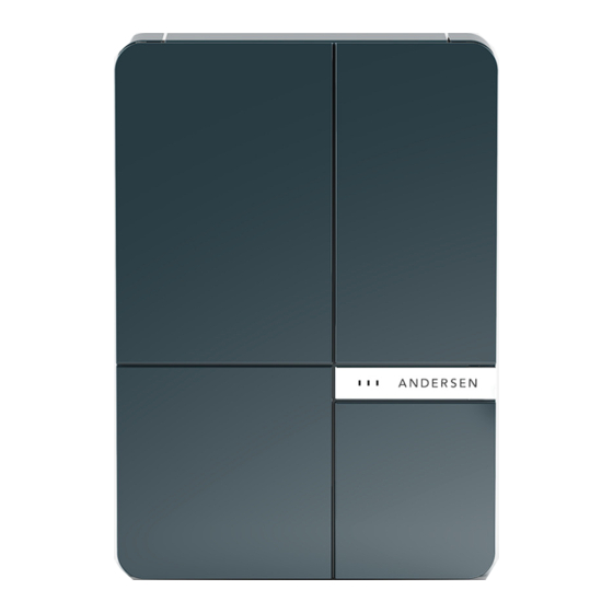
- Page 2 A1 PRODUCT FEATURES Vehicle charging Serial Number cable magic slot Evoflek extra Repair work to the Andersen A1 is not storage flexible charge cable permitted and may only be completed by Andersen or an Andersen trained expert. Only pull the charging cable out of the vehicle plug using the charging socket, never pull the cable.
- Page 3 A N D E R S E N A 1 I N S T A L L A T I O N G U I D E A N D E R S E N Fig F1.1 C H E C K T H E P A R T S Check the supplied carton(s).
- Page 4 A N D E R S E N A 1 I N S T A L L A T I O N G U I D E A N D E R S E N Fig F2.1 Q U I C K O V E R V I E W Read these instructions carefully and study the device to familiarise yourself with it before you attempt to install,...
-
Page 5: Select The Installation Location
GENERAL CRITERIA FOR SELECTING AN INSTALLATION SITE The Andersen A1 has been designed for indoor and outdoor domestic use. If possible, install the Andersen A1 so that it is protected from direct rainfall and sunlight to avoid the effects of weather, 200mm 200mm... - Page 6 The maximum screw diameter that can be used is 6mm. NOTE the weight of Fig F4.2 the Andersen A1 is about 15 Kg depending on the variant. Wire the Back Panel to the mains supply. The RCD assembly 2-1 can be 2.2.1...
- Page 7 2.2.5 Carry out normal wiring safety checks. Note the metal cabinet of the Andersen A1 is NOT earthed. 2.2.6 Replace the RCD front panel. 2-1-5 2.2.7 Replace the RCD assembly if it was removed for wiring.
- Page 8 A1 CHARGER CONTROLLER The Andersen A1 charger controller supplied set to charge at 32 Amps maximum. The Andersen A1 can be re set to a maximum charge current of 20 Amps or 16 Amps. To change the maximum charge current: - 3-1-1 3.3.1...
-
Page 9: The Control Unit
A N D E R S E N A 1 I N S T A L L A T I O N G U I D E A N D E R S E N 4. FIT THE DECORATIVE FRONT PANEL TO Fig F6.1 THE CONTROL UNIT Lay decorative front panel 1-0 on a soft... - Page 10 A N D E R S E N A 1 I N S T A L L A T I O N G U I D E A N D E R S E N 5. FIT THE CONTROL UNIT Fig F7.3 TO THE BACK PANEL 2-1-7...
- Page 11 A N D E R S E N A 1 I N S T A L L A T I O N G U I D E A N D E R S E N locate the two fixing lugs 3-3 on Fig F7.6 the control unit and the hanging brackets 2-2 on the back panel see...
- Page 12 2-RS. Allow the control unit to hang freely see fig F7.6.2 5.10 Push the bottom of the Andersen A1 unit towards the wall and fit the two anti-tamper retaining screws 4-3 to the bottom of the control unit see fig F7.7.
- Page 13 3-6 It can be rewound it may be necessary to shade the clockwise or anticlockwise to suit Andersen A1 to see the illuminated the client. Put the vehicle socket parts. back in the top chamber and close the top chamber door.
-
Page 14: Description Of Parts
No part of this documentation may be reproduced (photocopying, scanning or any other procedures) or processed, copied or distributed in any form Original installation instructions using electronic systems without the written consent of Andersen EV. Copyright ©2017 Andersen EV UK Contraventions are liable to compensation.
Need help?
Do you have a question about the A1 and is the answer not in the manual?
Questions and answers