Ingersoll-Rand HL1500K Parts, Operation And Maintenance Manual

Ingersoll-Rand HL1500K Parts, Operation And Maintenance Manual

Air chain hoist
Table of Contents

Advertisement

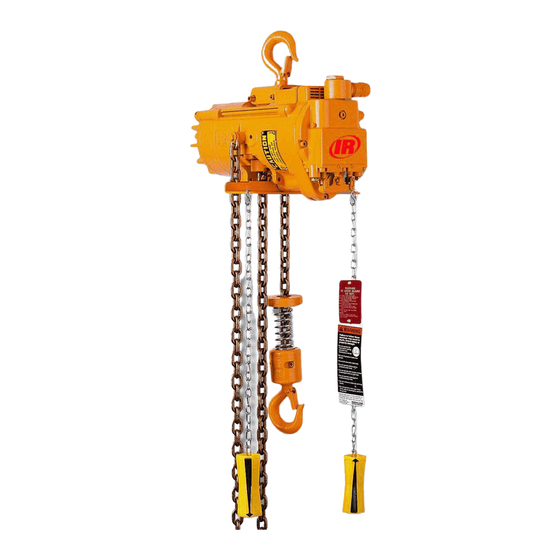
PARTS, OPERATION AND MAINTENANCE MANUAL
HL1000K
1000 kg (1 ton)
HL2000K
2000 kg (2 ton)
READ THIS MANUAL BEFORE USING THESE PRODUCTS. This manual
contains important safety, installation, operation and maintenance
information. Make this manual available to all persons responsible for
the operation, installation and maintenance of these products.
Do not use this hoist for lifting, supporting, or transporting people or lifting or
supporting loads over people.
Always operate, inspect and maintain this hoist in accordance with American National
Standards Institute Safety Code (ASME B30.16) and any other applicable safety codes
and regulations.
Refer all communications to the nearest Ingersoll-Rand Material Handling Office or
Distributor.
Form P6587
Edition 6
May 1997
03531837
© 1997 Ingersoll-Rand Company
for
AIR CHAIN HOIST MODELS*
HL1000KR
1000 kg (1 ton)
Spark Resistant
HL3000K
3000 kg (3 ton)
* Capacities of hoists are in metric tons (1 metric ton = 2,200 lbs.)
WARNING
1500 kg (1-1/2 ton)
HL4500K
4500 kg (4-1/2 ton)
1
Form P6587
HL1500K
HL6000K
6000 kg (6 ton)

Advertisement

Table of Contents
loading
Need help?

Need help?

Do you have a question about the HL1500K and is the answer not in the manual?

Questions and answers

Summary of Contents for Ingersoll-Rand HL1500K

  • Page 1 Always operate, inspect and maintain this hoist in accordance with American National Standards Institute Safety Code (ASME B30.16) and any other applicable safety codes and regulations. Refer all communications to the nearest Ingersoll-Rand Material Handling Office or Distributor. Form P6587...
  • Page 2: Table Of Contents

    TABLE OF CONTENTS Safety Information Danger, Warning, Caution and Notice ................................3 Safety Summary ......................................... 3 Safe Operating Procedures ....................................4 Warning Tags and Labels ....................................4 Specifications Model Code Explanation ....................................6 Installation Hoist Checks ........................................7 Hoist Mounting ........................................7 Chain Container .........................................
  • Page 3: Safety Information

    York, NY 10018. information which is important but not hazard-related. This manual has been produced by Ingersoll-Rand to provide dealers, mechanics, operators and company personnel with the Safety Summary information required to install, operate, maintain and repair the products described herein.
  • Page 4: Safe Operating Procedures

    14. Never carry loads over people. 15. Before each shift, check the hoist for wear or damage. Ingersoll-Rand recognizes that most companies who use hoists Check brakes, limit stops, etc. have a safety program in force in their plants. In the event you 16.
  • Page 5: Specifications

    Chain Model No. Falls (kg) down down down down down down HL1000K 1000 11.3 12.2 HL1000KR 38.1 HL1500K 1500 HL2000K 2000 56.6 HL3000K 3000 58.5 HL4500K 4500 10.5 87.5 HL6000K 6000 112.5 Notes: Based on hook mounted hoist with standard 10 ft (3 m) lift and one motor pendant control.
  • Page 6: Model Code Explanation

    Model Code Explanation Example: HL1000K-2C10-C6S 1000K Series: Chain Type: = Link Base Model: 1000K = 1000 kg 1 metric ton (2,200 lbs) 1000KR 1000 kg 1 metric ton (2,200 lbs) Spark Resistant 1500K 1500 kg 1-1/2 metric tons (3,300 lbs) 2000K 2000 kg 2 metric tons (4,400 lbs) 3000K...
  • Page 7: Installation

    Trolley bolt nuts (207) and (220) torque requirements: • The supporting member must position on the saddle of the On HL1000K, HL1500K, HL2000K and HL3000K hoists hook. Ensure hoist does not tilt to one side or the other. torque to 150 ft lbs (203 Nm).
  • Page 8: Chain Container

    When installing the hoist and trolley on the beam, make certain NOTICE the side plates are parallel and vertical. After installation, operate the trolley over the entire length of the beam with rated • Always use an air line filter and lubricator with an HLK load suspended 4 to 6 inches (100 to 150 mm) off the floor.
  • Page 9: Pendant Control Adjustments

    Pendant Control Adjustments For maximum performance and control, adjust the bleed screws (19) or (336 [old style]) as follows: The bleed adjustment screws (19) or (336 [old style]) used on Loosen the adjustment screw locknut (21) or (337 [old hoists with a pendant control are factory adjusted to provide style]).
  • Page 10: Operation

    For detailed information on these products refer to Ingersoll-Rand Manual Form Number P6778 or contact your nearest distributor or the factory. Operation of the hoist is the same for all pendants listed in this section: To lift a load, depress the hoist pendant raise lever.
  • Page 11: Pull Chain Control

    Two Function, Four Lever Pendant Pull Chain Control The four lever pendant is designed to provide a single station for The pull chain provides the operator with a local hoist operating control of hoist and trolley operations. station. The following operating directions are as viewed from Refer to Dwg.
  • Page 12: Inspection

    INSPECTION HOOKS. Check for wear or damage, increased throat WARNING width, bent shank or twisting of hook. Replace hooks which exceed the throat opening and/or saddle dimension • All new, altered or modified equipment should be inspected discard widths specified in Table 2 (refer to Dwg. and tested by personnel instructed in safety, operation and MHP0040) or exceed a 10°...
  • Page 13: Periodic Inspection

    New Hook Discard Hook New Hook Discard Hook HL1000K and 1.12 28.4 1.21 30.7 1.06 26.9 1.14 29.0 1.37 34.8 1.48 37.6 HL1500K HL2000K 1.06 26.9 1.14 29.0 1.50 38.1 1.62 41.1 1.50 38.1 1.62 41.1 HL3000K 1.50 38.1 1.62 41.1...
  • Page 14: Hoists Not In Regular Use

    Table 3, replace the Standby hoists should be inspected at least semiannually in entire chain. Always use a genuine Ingersoll-Rand accordance with the requirements of “Frequent Inspection”. Material Handling replacement chain. In abnormal operating conditions hoists should be inspected at shorter intervals.
  • Page 15: Inspection And Maintenance Report

    Refer to the Parts, Operation and Maintenance Manual “INSPECTION” section for general inspection criteria. Refer to appropriate National Standards and Codes of practice. If in doubt about an existing condition contact the nearest Ingersoll-Rand Distributor or the factory for technical assistance.
  • Page 16: Troubleshooting

    TROUBLESHOOTING This section provides basic troubleshooting information. Specific causes to problems are best identified by thorough inspections performed by personnel instructed in safety, operation and maintenance of this equipment. The chart below provides a brief guide to common hoist symptoms, probable causes, and remedies. SYMPTOM CAUSE REMEDY...
  • Page 17: Lubrication

    (111) in the end of the idler replacement of parts, lubricate as follows: wheel shafts (110). Coat all motor parts with a light film of Ingersoll-Rand Pneu-Lube® Medium Oil No. 50 or a good quality Housing hydraulic oil before assembling.
  • Page 18: Maintenance

    Proper use, inspections and maintenance increase the life and depth of 0.010 to 0.012 inch (0.25 to 0.35 mm). When the outer usefulness of your Ingersoll-Rand equipment. During assembly, hardened case layer is worn through, additional wear will lubricate gears, nuts, capscrews and all machined threads with progress rapidly and the strength of the chain will be applicable lubricants.
  • Page 19: Initial Chain Installation

    The following steps describe the initial installation of chain on double fall hoists that do not have load chain installed. Complete steps 1 through 4 of “HL1000K, HL1000KR and HL1500K Chain Installation” section. Refer to MHP0472, TPA706-4, and TPA706-3. WARNING •...
  • Page 20 HL4500K and HL6000K The following steps describe the initial installation of chain on three or four fall hoists that do not have load chain installed. Remove the brake spring and piston housing, brake discs and brake plates to expose the brake driver. Place the edge of the first link of load chain in a pocket of the hoist powered chain wheel.
  • Page 21 Lubricate the load chain as described in the NOTICE “LUBRICATION” section. Operate the hoist fully in both directions without a load attached. Hoist must operate • The load chain links that were standing links on the smoothly without sticking, binding or chain ‘jumping’. Test powered chain wheel are also standing links on the bottom hoist completely as described in the ‘Testing’...
  • Page 22: Chain Replacement

    Raise the hoist hook (HL1000K, HL1000KR, HL1500K) or NOTICE hook block (HL2000K, HL3000K, HL4500K, HL6000K) to a position near the hoist where it can be properly • The load chain links that are standing links on the powered supported and restrained from movement.
  • Page 23: Servicing The Filter And Strainer

    Run the hook up and down several times under power with NOTICE no load to ensure the load chain is running smoothly over the chain wheels. There must be no apparent binding or • On double chain fall hoists the total number of load chain evidence of malfunctioning.
  • Page 24 Unscrew the valve chest screws (26) and (27) and remove Remove the brake plates (78) and brake discs (79) from the the valve chest (6) and valve chest gaskets (25). gear case cover. Remove ‘O’ ring (air port) (77) and Unscrew and remove the swivel inlet assembly.
  • Page 25: Cleaning, Inspection And Repair

    Do not remove the needle roller bearings (63A) or (58) Clean all hoist component parts in solvent (except for the brake from the planet frame or planet gears unless required for discs). Care must be taken to clean components thoroughly, but repair.
  • Page 26 Stand the planet gear frame (54) on the table of an arbor press with its short hub upward. Wipe a thin film of Ingersoll-Rand No. 11 grease on both 13. Install the pinion gear (72) with a tooth of the pinion ends of the planet gears (57) and on the planet gear thrust entering each of “X”...
  • Page 27 10. To install in hoist, refer to ‘Hoist Assembly’ section. Brake Assembly Refer to Dwg. TPB704-3. Lightly coat the piston seals (84) and (85) with ‘O’ ring lubricant, and install them in their respective grooves on the brake piston (83). Taking care not to cut the seals, slide the piston into the brake spring and piston housing (80).
  • Page 28 Lubricate the gear splines on the ring gear (52) shaft and this style valve chest if it cannot be repaired. The following the chain wheel (51A) with Ingersoll-Rand No. 11 grease. assembly instructions are provided for reference only. Install the chain wheel on ring gear shaft.
  • Page 29 13. Place a housing gasket (3) on the motor end of the hoist 23. Stand the hoist upright on the brake end. Place the valve and install the valve chest plate (28) and screws (30). chest gasket (25) on the valve chest plate, making certain Check that motor shaft (38) turns freely by hand without that the small flapper is properly positioned in the recess sticking or binding.
  • Page 30 The strain relief cable (175) must be long enough to allow the Chain Container pendant hose to hang nearly straight yet short enough to absorb To Install Fabric Container the pendant weight and forces. Position the mounting bracket (301) between the bosses at the bottom of the hoist in the area of the chain opening.
  • Page 31: Load Test

    Disconnect the last link of load chain from hoist by NOTICE separating connecting link (91). Slide stop ring approximately 16 links (minimum of 5.38 in (136 mm)) • Operate the hoist to naturally pile chain into the chain from dead end of load chain. Refer to Dwg. MHP1226. container.
  • Page 32: Assembly Drawing And Parts List Table Of Contents

    Motor Assembly Parts Drawing (Dwg. TPB703-3) and Parts List ......................42 Top Lug Assembly Drawing (Dwg. TPC449-3) and Parts List ........................43 HL1000K, HL1000KR and HL1500K Hook Assembly Parts Drawing (Dwg. MHP1105) ................ 44 HL1000K, HL1000KR and HL1500K Hook Assembly and Parts List ......................45 HL2000K and HL3000K Hook Assembly Parts Drawing (Dwg.
  • Page 33: Assembly Drawings And Parts Lists

    HOIST PARTS SECTION GUIDE...
  • Page 34: Hoist Housing Assembly Parts Drawing (Dwg. Mhp1065)

    HOIST HOUSING ASSEMBLY PARTS DRAWING...
  • Page 35: Hoist Housing Assembly Parts List

    HOIST HOUSING ASSEMBLY PARTS LIST ITEM DESCRIPTION QUANTITY PART OF PART TOTAL NUMBER Housing Assembly HLK-A300 Housing Not sold separately * • Throttle Shaft Bearing H54U-511 Vent Plug CE210-120 Level and Drain Plug R0H-377 • Housing Gasket ML50K-445 Chain Guide HLK-741 Chain Guide Screw G57T-634...
  • Page 36: Hoist Valve Chest Assembly Parts Drawing (Dwg. Tpa958-1)

    HOIST VALVE CHEST ASSEMBLY PARTS DRAWING...
  • Page 37: Hoist Valve Chest Assembly Parts List

    Gasket MLK-117A Plug, Pipe (Pull Chain) ** R0H-377 MLK-241 Plug, Vent (Pull Chain) ** P250-546 Cover Assembly MLK-A238A Ingersoll-Rand Logo HRA20A-201 • Valve Chest Cover Seal R000BR-210 Fitting, Elbow (Pendant) ** UWD-161 Bleed Adjustment Screw MLK-370 Fitting, Nipple (Pendant) **...
  • Page 38: Hoist Gearing Assembly Parts Drawing (Dwg. Tpb705-2)

    HOIST GEARING ASSEMBLY PARTS DRAWING...
  • Page 39: Hoist Gearing Assembly Parts List

    Gear Case Screw 21-702 Planet Frame Bearing HLK-96 Lockwasher UW50A30-58 Planet Gear Assembly HLK-A10 Pinion Gear Gear Bearing 182A83-606 For HL1500K, • HLK-319-12 Gear Thrust Bearing R02W-696 HL3000K, HL4500K and HL6000K Gear Thrust Race CE210-603 Planet Shaft HLK-191 Pinion Gear...
  • Page 40: Hoist Brake Assembly Parts Drawing (Dwg. Tpb704-3)

    HOIST BRAKE ASSEMBLY PARTS DRAWING...
  • Page 41: Hoist Brake Assembly Parts List

    • Retainer Screw HLK-640 HL1000K and HL1000KR ML1000K-99 • ‘O’ Ring (Air Port) PS3-67 (1 ton) Brake Plate ML50K-834A HL1500K (1-1/2 ton) HL1500K-99 • Brake Disc ML50K-855A HL2000K (2 ton) HL2000K-99 Brake Spring and Piston HL3000K (3 ton) HL3000K-99 MLK-A395A...
  • Page 42: Motor Assembly Parts Drawing (Dwg. Tpb703-3) And Parts List

    MOTOR ASSEMBLY DRAWING AND PARTS LIST ITEM DESCRIPTION QTY. PART ITEM DESCRIPTION QTY. PART OF PART TOTAL OF PART TOTAL • Motor Assembly HLK-A53 Vane Packet set of 7 MR-42-7 Motor Shaft HLK-316 Cylinder MR-3A Cylinder Dowel R3H-434 Motor Shaft Rear Retainer MLK-120 Ring Front End Plate...
  • Page 43: Top Lug Assembly Drawing (Dwg. Tpc449-3) And Parts List

    TOP LUG ASSEMBLY DRAWING AND PARTS LIST PART NO. ITEM DESCRIPTION QTY. OF PART TOTAL HL1000K/HL1000KR HL1500K HL2000K/HL3000K - - - Top Lug Kit HLK-K444A HL3000K-K444A • Locking Tab HLK-322 Lug Block HLK-444A Lug Mounting Block HLK-425 Bolt (1.5 inch long) 215-36 Bolt (1.25 inch long)
  • Page 44: Hl1000K, Hl1000Kr And Hl1500K Hook Assembly Parts Drawing (Dwg. Mhp1105)

    HL1000K, HL1000KR AND HL1500K HOOK ASSEMBLY PARTS DRAWING...
  • Page 45: Hl1000K, Hl1000Kr And Hl1500K Hook Assembly And Parts List

    HL1000K, HL1000KR AND HL1500K HOOK ASSEMBLY PARTS LIST PART NO. ITEM DESCRIPTION QTY. OF PART TOTAL HL1000K and HL1500K HL1000KR Load Chain: Specify Load Chain (Zinc Plated) H745Z - - - Length Load Chain (Stainless Steel) in feet - - -...
  • Page 46: Hl2000K And Hl3000K Hook Assembly Parts Drawing (Dwg. Mhp1106)

    HL2000K AND HL3000K HOOK ASSEMBLY PARTS DRAWING...
  • Page 47: Hl2000K And Hl3000K Hook Assembly Parts List

    HL2000K AND HL3000K HOOK ASSEMBLY PARTS LIST PART NO. ITEM DESCRIPTION QTY. OF PART TOTAL HL2000K HL3000K Load Chain: Specify Load Chain (Zinc Plated) Length H745Z in feet Bullard Bullard Top Hook: Standard Bronze Standard Bronze Burnham Burnham Top Hook Assembly HL2000K-K590 - - - HL3000K-K590...
  • Page 48: Hl4500K Hook Assembly Parts Drawing (Dwg. Tpa1041)

    HL4500K HOOK ASSEMBLY PARTS DRAWING...
  • Page 49: Hl4500K Hook Assembly Parts List

    HL4500K HOOK ASSEMBLY PARTS LIST PART NO. ITEM DESCRIPTION QTY. OF PART TOTAL Standard Bronze Bullard Burnham Upper Suspension Housing HL4500K-590 Capscrew KX-36 Capscrew D01-339 Tab Washer HLK-322 Idler Wheel Assembly HL6000K-A380 Idler Wheel Bearing 48NB-765 Idler Wheel Seal C6H20A28-754 Idler Wheel Thrust Washer 2 each Idler Wheel HL6000K-974...
  • Page 50: Hl6000K Hook Assembly Parts Drawing (Dwg. Tpa1040)

    HL6000K HOOK ASSEMBLY PARTS DRAWING...
  • Page 51: Hl6000K Hook Assembly Parts List

    HL6000K HOOK ASSEMBLY PARTS LIST PART NO. ITEM DESCRIPTION QTY. OF PART TOTAL Standard Bronze Bullard Burnham Upper Suspension Housing HL6000K-590 Capscrew KX-36 Capscrew D01-339 Tab Washer HLK-322 Limit Stop Tube HL6000K-259 Idler Wheel Assembly HL6000K-A380 Idler Wheel Bearing 1 each Idler Wheel 48NB-765 Idler Wheel Seal 2 each Idler Wheel...
  • Page 52: Pendant Assembly Parts Drawing (Dwg. Tpa0882-3)

    PENDANT ASSEMBLY PARTS DRAWING...
  • Page 53: Pendant Assembly Parts List

    PENDANT ASSEMBLY PARTS LIST ITEM DESCRIPTION QTY. ITEM DESCRIPTION QTY. PART NO. PART NO. OF PART TOTAL OF PART TOTAL Pendant Kit* MLK-K269C Strain Relief Cable BWR3A (specify length) Pendant Assembly ** MLK-A269C Pendant Throttle Valve MLK-K264B Clamping Sleeve MLK-521 (see note 3) •...
  • Page 54: Fabric Chain Container Assembly Parts Drawing (Dwg. Tpc451-3)

    FABRIC CHAIN CONTAINER ASSEMBLY PARTS DRAWING...
  • Page 55: Fabric Chain Container Assembly Parts List

    FABRIC CHAIN CONTAINER ASSEMBLY PARTS LIST ITEM DESCRIPTION QTY. PART OF PART TOTAL Fabric Chain Container Kit (single fall hoist capacity 20 ft [6 m] or on double fall HLK-K749-20 hoist 10 ft [3 m]) - - - Fabric Chain Container Kit (single fall hoist capacity 40 ft [12 m] or on double fall HLK-K749-40 hoist 20 ft [6 m]) Fabric Chain Container (20 ft [6 m] of chain capacity)
  • Page 56: Metal Chain Container Assembly Parts Drawing (Dwg. Mhp1029)

    METAL CHAIN CONTAINER ASSEMBLY PARTS DRAWING...
  • Page 57: Metal Chain Container Assembly Parts List

    METAL CHAIN CONTAINER ASSEMBLY PARTS LIST ITEM DESCRIPTION QTY. PART OF PART TOTAL NUMBER Metal Chain Container Kit (single fall hoist capacity 20 ft [6 m] or on double fall HLK-K750-20 hoist 10 ft [3 m]) Metal Chain Container Kit (single fall hoist capacity 40 ft [12 m] or on double fall - - - HLK-K750-40 hoist 20 ft [6 m])
  • Page 58: Trolley Assembly Information

    (I-Beam) (WF-Beam) Form No. CE120-K426 CE120-K426T HL1000K 3.00 to 5.00 76 to 127 P6720 CE120-KR426 CE120-KR426T HL1000KR HL1500K and 1-1/2 and 2 HRA40A-A700 HRA40A-AT700 3.33 to 6.00 84 to 152 contact factory HL2000K TP3A-K426 TP3A-K426T HL3000K 3.2 to 5.50 81 to 140...
  • Page 59: Repair And Conversion Kits

    REPAIR AND CONVERSION KITS Pendant Conversion Kit: Includes all components necessary to convert a pull chain throttle hoist to pendant control operation. Part No. MLK-AL269C (04307310) used on all MLK, MLKR, HLK and HLKR hoists. Length of pendant hose must be specified when ordering.
  • Page 60: Accessories

    ACCESSORIES FILTERS, REGULATORS AND LUBRICATORS Filter Part Number Lubricator Part Number Filter, Regulator and Regulator Size Lubricator Kit Polycarbonate Polycarbonate Part Number NPTF Metal Bowl * Metal Bowl Part Number Bowl * Bowl C28-04-FKG0-28 F20-04-000 F28-04-SK00-28 R28-04-F0G0-28 L28-04-LK00-28 L20-04-G00 C31-06-G00 F30-06-000 F30-06-G00 R28-06-F0G0-28...
  • Page 61: Old Style Valve Chest Assembly Drawing (Dwg. Tpa883-3) And Parts List

    OLD STYLE VALVE CHEST ASSEMBLY DRAWING AND PARTS LIST Old Style Hoist Valve Chest conversion to New Style Hoist Valve Chest Information: Valve Chest Converison Kit Part Number MLK-K545B New Style Hoist refererences apply to hoists with second letter of the serial number other than A through G or with second and third letters other than HA, HB, or HC.
  • Page 62: Parts Ordering Information

    Ingersoll-Rand distributor in The use of other than Ingersoll-Rand Material Handling your locality.
  • Page 63: Warranty Information

    LIMITED LIMITED WARRANTY WARRANTY WARRANTY Ingersoll-Rand Company (I-R) warrants to the I-R makes no other warranty, and all implied original user its Hoists and Winches (Products) to be warranties including any warranty of free of defects in material and workmanship for a merchantability or fitness for a particular purpose period of one year from the date of purchase.
  • Page 64: Offices And Addresses

    Fax: (416) 213-4510 Fax: (310) 948-1828 Order Desk Asia Pacific Operations Fax: (416) 213-4605 Ingersoll-Rand (Japan) Ltd. Philadelphia, PA Shin-Yokohama Square Bldg. P.O. Box 425 Regional Sales Offices Floor) 900 E. 8th Ave., Suite 103 2-3-12 Shin-Yokohama, King of Prussia, PA 19406...

This manual is also suitable for:

Hl4500kHl6000kHl1000kHl1000krHl2000kHl3000k

Table of Contents