
Related Manuals for GE HEALTHCARE B40


Summary of Contents for GE HEALTHCARE B40
- Page 1 GE Healthcare PROCARE* Monitor B40/B20 User’s Reference Manual PROCARE Monitor B40/B20 English 2050801-001 D (Paper) © 2011 General Electric Company. All Rights Reserved.
- Page 3 PROCARE Monitor B40/B20 User's Reference Manual Related to software license VSP-A Monitoring functions 0459 Conformity according to the Council Directive 93/42/EEC concerning Medical Devices. All specifications are subject to change without notice. Document no. 2050801-001 D July 18, 2011 GE Medical Systems Information Technologies, Inc.
- Page 4 Trademarks Dash, PROCARE, DINAMAP, EK-Pro, Trim Knob, Unity Network, Datex, Ohmeda, S/5, D-fend, D- fend+, Mini D-fend, OxyTip+, EarSat, FingerSat, FlexSat are trademarks of GE Healthcare. All other product and company names are property of their respective owners.
-
Page 5: Table Of Contents
Table of Contents Introduction About this device ..............1-1 Intended purpose (Indications for use) . - Page 6 B40/B20 Patient Monitor Technical specification............2-25 General Specifications .
- Page 7 Alarms Overview ................5-1 Safety precautions.
- Page 8 B40/B20 Patient Monitor Modifying digit fields............6-9 Modifying split screen.
- Page 9 Changing the paper speed ........... 8-4 Controlling the recording time .
- Page 10 B40/B20 Patient Monitor Displaying ECG and heart rate ..........11-3 Preparing the patient and placing the electrodes .
- Page 11 Improving waveform readability........... 12-6 Correcting the respiration number .
- Page 12 B40/B20 Patient Monitor 15 Invasive blood pressure Safety precautions..............15-1 Warnings.
-
Page 13: Document No
Index Index-1 Appendix A: Installation and checkout form, B40/B20 Document no. 2050801-001... - Page 14 B40/B20 Patient Monitor Document no 2050801-001...
-
Page 15: Introduction
1 Introduction... -
Page 17: About This Device
This device is a portable multiparameter unit to be used for monitoring and recording of, and to generate alarms for, multiple physiological parameters of adult, pediatric, and neonatal patients in a hospital environment and during intra-hospital transport. The B40/B20 Patient Monitor is intended for use under the direct supervision of a licensed health care practitioner. -
Page 18: Printed Copies Of This Manual
CE marking information CE compliance The B40/B20 Patient Monior bears CE Mark CE-0459 indicating its conformity with the provisions of the Council Directive 93/42/EEC concerning medical devices and fulfills the essential requirements of Annex I of this directive. The country of manufacture can be found on the equipment labeling. -
Page 19: Warranty
Introduction Warranty This Product is sold by GE Healthcare (“GE”) under the warranty set forth in the following paragraphs. Such warranty is extended only with respect to the purchase of this Product directly from GE or GE’s Authorized Dealers as new merchandise and is extended to the Buyer thereof, other than for the purpose of resale. -
Page 20: About This Manual
B40/B20 Patient Monitor About this manual This User’s Reference Manual describes the functions offered by the B40/B20 patient monitor running the software license VSP-A. As the monitor setup may vary, some menus, displays and functions described may not be available in the monitor you are using. -
Page 21: Related Documentation
Push the Trim Knob. Related documentation Installation, technical solutions and servicing: PROCARE Monitor B40/B20 Technical Reference Manual Options and selections of the software: PROCARE Monitor B40/B20 Default Configuration Worksheet Compatible supplies and accessories: PROCARE Monitor B40/B20 Supplies and Accessories ... -
Page 22: Safety Precautions
B40/B20 Patient Monitor Safety precautions The following list contains all the general warnings and cautions you should know before starting to use the system. Warnings and cautions specific to parts of the system can be found in the relevant section. -
Page 23: Cautions
Introduction the device. If you do not observe this sequence, there is a risk of coming into contact with line voltage by inserting metal objects, such as the pins of leadwires, into the sockets of the power cord by mistake. •... -
Page 24: Esd Precautionary Procedures
B40/B20 Patient Monitor ESD precautionary procedures • To avoid electrostatic charges to build up, it is recommended to store, maintain and use the equipment at a relative humidity of 30% or greater. Floors should be covered by ESD dissipative carpets or similar. Non-synthetic clothing should be used when working with the component. -
Page 25: System Description
2 System description... -
Page 27: Safety Precautions
System description 2 System description Safety precautions Warnings • All system devices must be connected to the same power supply circuit • EXCESSIVE LEAKAGE CURRENT - Do not use a multiple socket outlet or extension cord. • INTERFACING OTHER EQUIPMENT - Devices may only be interconnected with each other or to parts of the system when it has been determined by qualified biomedical personnel that there is no danger to the patient, the operator, or the environment as a result. -
Page 28: Principles Of Functions
B40/B20 Patient Monitor Principles of functions The B40/B20 monitor is a modular multiparameter patient monitor. The monitor is especially designed for monitoring in PACU, ED, Wards, Step down units, Intra-hospital transport, Private sectors, Alternative care in mature markets; PACU, ED, Wards, Step down units (low/mid critical care), Intra-hospital transport, ICU &... -
Page 29: System Introduction
System description System introduction The B40/B20 monitor system may consist of the elements shown below. NOTE: Your system may not include all these components. Consult your local representative for the available components. Figure 2-1 B40/B20 patient monitor system B40/B20 monitor frame... -
Page 30: Components
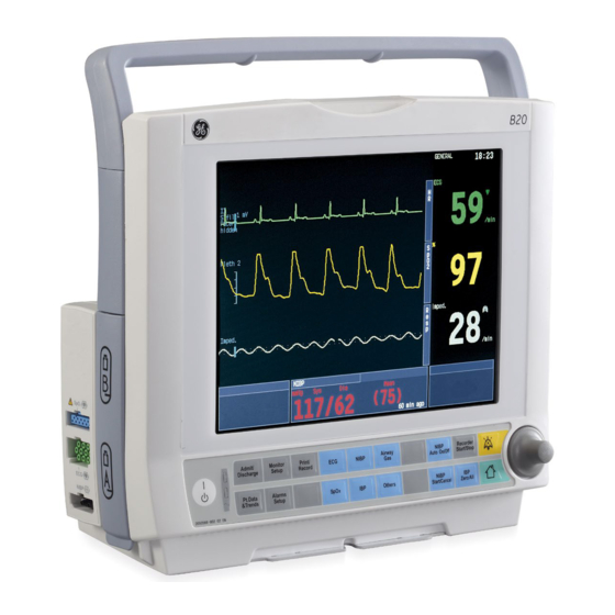
B40/B20 Patient Monitor Components The basic components of the B40/B20 are the monitor frame with hemo module. Figure 2-2 B40/B20 monitor front panel Transportation handle Alarm light The Trim knob Command board keys Battery compartment Guide rail for GCX mounting... -
Page 31: Rear Panel Connections
System description Rear panel connections Figure 2-3 Rear panel connections Receptacle for power cord Serial port Defibrillator connector Nurse call connector Network connector Equipotential connector Multi I/O connector NOTE: The Multi I/O with ports 2,3,4 are optional parts for customer. E-miniC module Figure 2-4 E-miniC... -
Page 32: Keyboards
B40/B20 Patient Monitor Keyboards You can control monitoring through the keys on the Command Board. For more information, see section "Monitoring basic." Command Board keys Figure 2-5 Command Board keys ON/standby key Mains power ON (lit) or OFF (dark): indicates mains For admitting or discharging a patient;... -
Page 33: Batteries
NOTE: Before using the monitor for the first time, charge the batteries to their full capacity. Charging time is two hours per battery pack. The B40/B20 has two lithium-ion batteries at most, located in the battery compartment. They can be charged separately, and screen symbols and monitor frame LEDs indicate their charging level and possible failure, see below. -
Page 34: Battery Indicators
B40/B20 Patient Monitor Battery indicators The B40/B20 messages, screen symbols and front panel LED indicators tell the user about the status of the batteries. For screen symbols, see page 2-14. For LED indicators, consult the table below and for messages, see section “Troubleshooting.”... -
Page 35: Conditioning A Battery
Real-time multi-parameter waveforms • Graphic/tabular trends • Real-time Alarm, including Arrhythmia alarms: ASYSTOLE, VFIB/VTAC, VTACH • Patient admit/discharge & patient name update • Multiple parameters alarm setting Also in Unity network, B40/B20 support to set up parameters and waveforms on CIC remotely. -
Page 36: Symbols
B40/B20 Patient Monitor Symbols On the rear panel this symbol indicates the following warnings and cautions: Electric shock hazard. Do not open the cover or the back. Refer servicing to qualified personnel. For continued protection against fire hazard, replace the fuse only with one of the same type and rating. - Page 37 System description Gas inlet. Gas outlet. Degree of ingress protection. IP21 Serial number SN,S/N Date of manufacture. This symbol indicates the date of manufacture of this device. The four digits identify the year. Maunfacturer: This symbol indicates the name and the address of the manufacturer. European authorized representative.
- Page 38 B40/B20 Patient Monitor This symbol indicates that the waste of electrical and electronic equipment must not be disposed as unsorted municipal waste and must be collected separately. Please, contact an authorized representative of the manufacturer for information concerning the decommissioning of your equipment.
- Page 39 System description Date of manufacture Do not immerse the sensor in liquids. Medical Equipment With respect to electrical shock, fire and mechanical hazards only in accordance with IEC 60601- 1, UL 60601-1; IEC 60601-2-27; IEC 60601-2-30; IEC 60601-2-34; IEC 60601-2-49; CAN/CSA C22.2 No.
-
Page 40: Abbreviations
B40/B20 Patient Monitor Abbreviations /min beats per minute, breaths per minute °C Celsius degree °F Fahrenheit degree µg microgram arm (describing location) alveolar arterial a/AO arterio-alveolar PO ratio AaDO alveolo-arterial oxygen difference anesthetic agent AAMI Association for the Advancement of Medical Instrumentation... - Page 41 System description Body body temperature blood pressure Brady bradycardia body surface area burst suppression ratio B-to-B beat-to-beat BTPS body temperature and pressure, saturated gas calculated/derived value chest C(a-v)O arteriovenous oxygen content difference C.C.O. continuous cardiac output cardiac function index C.I. cardiac index C.O.
- Page 42 B40/B20 Patient Monitor central venous pressure decibel double burst stimulation (NMT) delete Delta, De delta frequency band depr. depression desflurane diastolic pressure Diagn diagnostic (ECG filter) DIFF difference S/5 Device Interfacing Solution oxygen delivery oxygen delivery index digital signal converter...
- Page 43 System description end-systolic volume ESVI end-systolic volume index ET, Et end-tidal concentration EtAA end-tidal anesthetic agent EtBal end-tidal balance gas EtCO end-tidal carbon dioxide end-tidal nitrous oxide end-tidal oxygen ET-tube, ETT endotracheal tube EVLW extravascular lung water EVLWI extravascular lung water index expiratory foot (describing location) Fahrenheit degree...
- Page 44 B40/B20 Patient Monitor Hemo Calcs hemodynamic calculations reduced hemoglobin heat and moisture exchanger HMEF heat and moisture exchanger with filter hectopascal heart rate HRdiff heart rate difference height hardware hertz International Electrotechnical Comission inspiratory-expiratory ratio IABP intra-aortic balloon pump inspiratory capacity...
- Page 45 System description lateral pound liquid crystal display left cardiac work light emitting diode LVEDP left ventricular end diastolic pressure LVEDV left ventricular end diastolic volume LVSW left ventricular stroke work LVSWI left ventricular stroke work index minimum alveolar concentration maximum mbar millibar microgram...
- Page 46 B40/B20 Patient Monitor NIBP non-invasive blood pressure Ni-Cd nickel-cadmium Ni-MH nickel-metal hydride neuromuscular transmission nitric oxide NTPD normal temperature and pressure, dry gas Num. numerical oxygen oxygen extraction ratio oxygenated hemoglobin operation room oxygenation Oxy Calcs oxygenation calculations partial pressure...
- Page 47 System description arterial pH intramucosal pH (mixed) venous pH patient interface cable Pleth plethysmographic pulse waveform pacemaker PM non-capt. pacemaker non-capturing PM non-funct. pacemaker non-functioning Pmax maximum pressure Pmean mean pressure Pmin minimum pressure Ppeak peak pressure Pplat plateau (pause) pressure pulse rate Prev.
- Page 48 B40/B20 Patient Monitor Room room temperature respiratory quotient respiration rate (total) (measured) rhythm residual volume RVEDV right ventricular end-diastolic volume RVESV right ventricular end-systolic volume right ventricular pressure RVSW right ventricular stroke work RVSWI right ventricular stroke work index second...
- Page 49 System description software stroke volume variation systolic pressure time (min) temperature tesla T(BTPS) temperature in BTPS conditions first stimulus as % of the reference value (NMT) T1, T2 temperature channel identification on module Tab. tabular Tachy tachycardia Tbl, Tblood blood temperature Tcorr temperature correction Temp...
- Page 50 B40/B20 Patient Monitor V Run ventricular run V Tachy ventricular tachycardia WLAN wireless local area network weight extreme year years * with Fick equation 2-24...
-
Page 51: Technical Specification
System description Technical specification WARNING Operation of the monitor outside the specified values may cause inaccurate results. NOTE: Information in this section can be especially useful to clinicians. General Specifications Genenral specifications Size Monitor Without extension 312±5 mm (H) * 312±5 mm (W) * 158±5 mm (D) modules With extension modules 312±5 mm (H) * 352±5 mm (W) * 178±5 mm (D) - Page 52 B40/B20 Patient Monitor Battery life 300 cycles minimum to 50% capacity Battery information model SM 201-6; 11.1 V, 3.52 Ah Charging time 2 hours per battery pack Operation time Up to 4.5 hours Recorder Power comsumption Standby: < 1.2 W Printing: <...
-
Page 53: Parameters Specifications
System description Parameters specifications ECG specifications Leads available 3-lead configuration: I, II, III 5-lead configuration: I, II, III, aVR, aVL, aVF and VA QRS detection range 0.5 to 5mV QRS detection width (Q to 40 to 120 ms Defibrillation protection 5000 V, 360 J Recovery time <5 s... - Page 54 B40/B20 Patient Monitor Figure 3d 117 bpm Heart rate averaging computation (ANSI/AAMI EC13-2002 Section 4.1.2.1d): Average of 10 second median values The average time and time range ( ) to alarm (VFib or VTachy) for tachycardia waveform are as follows (ANSI/AAMI EC13-2002 Section 4.1.2.1g) Figure 4a halved 9.9 s (8.4 to 11.5 s)
- Page 55 System description Impedance respiration specifications Measurement range 4 to 120 resp/min Measurement accuracy ±5% or ±5 resp/min, whichever is greater Nomalized respiration <5.0 µA sensing current Impedance respiration 31.25 kHz carrier frequency GE SpO specifications Measurement and display 0 to 100% range Calibrated against functional oxygen saturation.
- Page 56 B40/B20 Patient Monitor Nellcor SpO specifications Measurement and display 1 to 100% range Measurement accuracy Adult 100 to 70% ±2 digits 100 to 70% ±3 digits Low perfusion 100 to 70% ±2 digits Display resolution 1% of SpO Display averaging...
- Page 57 System description Sensor Light Source Wavelength Infrared: 905 nm (nominal) Red: 660 nm (nominal) Power Dissipation Infrared: 22.5 mW (max) Red: 27.5 mW (max) NIBP Measurement technique Oscillometric with step deflation Supported modes Manual, automatic and stat Measurement time Adult/Pediatric inflate duration time less than 120 s Neonate cycle time less than 85 s Measurement ranges Systolic...
-
Page 58: Pulse Rate
± 0.1°C without temperature sensor Display resolution ± 0.1°C at 25 to 45 °C with reusable probes Probe types supported Use only GE Healthcare recommend temperature YSI probes. Temperature self-check At start-up and then every 10 minutes Probe type time response... - Page 59 System description Airway gases Sampling rate 150±25 ml/min (sampling line 2 to 3 m, normal conditions) Maximum sampling line length: Sampling delay 2.1 s typical with a 3-m sampling line Total system response 2.4 seconds typical with a 3-m time sampling line, including sampling delay and rise time Warm-up time 1 minute for operation...
- Page 60 B40/B20 Patient Monitor Resolution 1 breaths/min Non-disturbing gases are Ethanol C OH (<0.3%) those with a maximum Acetone (<0.1%) effect on the CO reading Methane CH (<0.2%) at 5.0 vol% < 0.2 vol%. The Nitrogen N (0 to 100%) effect is valid for specific...
-
Page 61: Installation
3 Installation... -
Page 63: Safety Precautions
Confirm that all components are undamaged. If any of the components is damaged, contact the shipper. Confirm that all components are included. If any of the components is missing, contact your GE Healthcare distributor. Choosing location Consider the following aspects: •... -
Page 64: Connection To Mains
B40/B20 Patient Monitor Connection to mains Connect the power cord to the mains power inlet at the back of the monitor and to the wall socket. NOTE: Before taking the monitor into use for the first time, the batteries should be fully charged. -
Page 65: Inserting And Removing The E-Minic Module
Installation Inserting and removing the E-miniC module To use the E-miniC module, your monitor need pre-configure the extension rack from manufacture. To insert module: Align the module with the insertion guides Push the module into the monitor frame until it clicks and stops. Pull the module outwards to insure the module is firmly seated. -
Page 66: Installation Checkout
These instructions include a “Installation and checkout form, B40/B20” to be filled in when performing the procedures. An electrical safety check and a leakage current test should be performed prior to the monitor installation. Please refer to Technical Reference Manual for details. -
Page 67: Visual Inspection
Check that the clock on the screen shows correct time. Readjust the time and date, if necessary. NOTE: The B40/B20 can’t be set as the TIME MASTER in network. You should adjust the time and date from the central station. -
Page 68: Network Connection
B40/B20 Patient Monitor • ECG: After connecting ECG cable, ‘leads off’ will display in the Waveform Field • NIBP: After connecting NIBP hose to module, ‘Adult/Pediatric’ or ‘Neonatal’ will display in NIBP Digital Field for several seconds • : After connecting SpO cable and sensor, SpO sensor will be lit. -
Page 69: Monitoring Basic
4 Monitoring basic... -
Page 71: Warnings
Monitoring basic 4 Monitoring basic Warnings • Connect only one patient to the monitor at a time. • Always make sure that necessary alarm limits are active and set according to the patient's clinical condition when you start monitoring. Using menus A menu is a list of functions or commands displayed on the monitor screen. - Page 72 B40/B20 Patient Monitor Select items in the menus with the Trim Knob. For example, to change what is displayed in the ECG display: Select the desired function by pressing the menu key. Turn the Trim Knob to move the highlight down in the menu to the desired selection.
- Page 73 Monitoring basic Push the Trim Knob to enter an adjustment window or a submenu Turn the Trim Knob to choose the desired option or selection in the window. Push the Trim Knob to confirm the selection. Normal Screen Press the key to return to normal monitoring display.
-
Page 74: Starting And Ending
B40/B20 Patient Monitor Starting and ending Warnings • Always make sure that necessary alarm limits are active and set according to the patient's clinical condition when you start monitoring a patient. • Connect only one patient to the monitor at a time. -
Page 75: Admitting A Patient
Monitoring basic IBP Zero All For example, zero the invasive pressure channels by pressing the key, and start NIBP measurement to get reference values. Enter or load patient data. Admitting a patient Monitoring of a new patient is started by admitting the patient. After the patient has been admitted, you can start monitoring and trend gathering. -
Page 76: Loading Previous Data
B40/B20 Patient Monitor Loading previous data If the patient has already been admitted on the same monitor and this monitor has been restarted, the Contin. Previous will be appeared. Admit/ Discharge Contin. Previous Select this to load the most recent patient trends from the monitor memory when less than 15 minutes has elapsed from the turn-off. -
Page 77: Automatic Discharge Of The Patient
Monitoring basic Automatic discharge of the patient The monitor will discharge a patient automatically after 24 hours when vital signs for some parameters (ECG, Art, NIBP, SpO , Resp and CO (with E-miniC only)) are not available. When this happens, all trend data will be cleared and alarm limits will be set to default values. Ending monitoring Print necessary data. -
Page 78: Using Modes
B40/B20 Patient Monitor Using modes The B40/B20 monitor has seven user modes. These user modes are predefined combinations of settings. They determine, for example, what is displayed on the screen and in trends and what the alarm limits are. In other words, by choosing a specific mode you get suitable settings on the screen without having to choose all features one by one. -
Page 79: Alarms
5 Alarms... -
Page 81: Overview
Alarms 5 Alarms Overview When an alarm for the monitored parameter becomes active: Figure 5-1 View of alarms Alarm messages appear in the message field in the order of priority. The measurement value flashes. The color (red, yellow) indicates the alarm category (high priority, medium priority). -
Page 82: Safety Precautions
B40/B20 Patient Monitor Safety precautions Warnings • Verify alarm processing is active and no arrhythmia occurred during power interruption. • Latched alarms are not retained through monitor reset if alarm condition is been removed. • Do not rely on secondary alarm system for receipt of alarm signal. -
Page 83: Alarm Categories
Provide additional information. Alarm light In addition to the audible, the B40/B20 has an alarm light, located in the top of the monitor. The alarm light flashes red, yellow and cyan according to the currently active highest priority alarm. The brightness of the light is fixed. -
Page 84: Alarm Tones
B40/B20 Patient Monitor Alarm tones The monitor has four options for alarm tones and patterns: ISO, ISO2, General and IEC. The ISO2 and ISO patterns are very similar. The difference is the rising sound of the tone pattern. The following frame colors and tones identify the alarm categories:... -
Page 85: Alarms Setup Menu
Alarms Alarms Setup menu You can view and adjust patient alarm limits in the Alarms Setup menu. Alarms Setup List of selections Exit from the alarm limit adjustment area back to Alarms Setup menu Parameter box with high and low limit values and a 10-minute trend showing the current status Adjust Limits Adjusts individual measurement alarm limits. - Page 86 B40/B20 Patient Monitor For more information on arrhythmia alarms, please see section "ECG." Alarm Volume Adjusts the volume of the audio alarms. The range is from 1 (soft) to 10 (loud). NOTE: Audible alarms cannot be totally silenced with the Alarm Volume function.
-
Page 87: Adjusting Alarm Limits
Alarms Adjusting alarm limits Adjusting limits Alarms Setup Press the key. Select Adjust Limits. Turn the Trim Knob to highlight the measurement. If the desired measurement is not displayed in the window, select Next Page. Push the Trim Knob to open an adjustment window. Turn the Trim Knob to change the limits and accept them by pushing it. -
Page 88: Changing Alarm Sources
B40/B20 Patient Monitor Changing alarm sources For NIBP, IBP1 or IBP2, CO2 FI or ET (with Configuration), you can select which measured values trigger the alarm. One or several alarm sources may be active at a time. Parameters Alarm triggered off by... -
Page 89: Silencing Alarms
Alarms Silencing alarms Silencing audible alarms temporarily NOTES: • The bedside alarms can also be silenced and acknowledged from the Central if this feature has been enabled in the Central configuration. In this case, the message 'Alarms silenced from Central' or 'Alarms acknowledged from Central' is displayed on the bedside monitor display. -
Page 90: Silencing Audible Alarms Permanently
B40/B20 Patient Monitor Silencing audible alarms permanently Silencing certain audible alarms entirely may be desirable for special cases. NOTES: • The following silencing selections (that is, all other selections than Activate Alarms) are Monitor Setup available only if alarm silencing has been enabled ( - Install/Service - Installation - Alarm Options - Show Audio ON/OFF - Yes). -
Page 91: Reactivating Alarms
Alarms Reactivating alarms Alarms Setup Press the key. Select Audio ON/OFF menu. Select Activate Alarms to turn on audible alarms. Deactivating alarms You can set the alarm limits temporarily to OFF for the following parameters: HR, SpO respiration rate. This way, you can silence a parameter without having to adjust the alarm limits. -
Page 92: Automatic Recording On Alarms
B40/B20 Patient Monitor Automatic recording on alarms An automatic local recording is possible when Asystole, Tachy/Brady, Art High/Low, V Fib or V Tachy alarms reach the red alarm level. When the red alarm level is reached, the recorder prints the ECG + Art waveforms. -
Page 93: Showing Alarm History
Alarms Showing alarm history • Pt. Data & Trends Alarm History Press the key and select . This displays a list of the last 20 alarms that have reached the yellow, red and cyan alarm level. The time and type of occurrence are displayed next to the alarm list items. -
Page 94: Enabling Or Disabling Alarm Silencing
B40/B20 Patient Monitor Enabling or disabling alarm silencing With this selection, you can determine whether the audible alarms can be turned off or not. Monitor Setup Press the key. Select Install/Service and enter the password. Select Installation - Alarm Options. -
Page 95: Latching Alarms
Alarms Latching alarms If the Latching Alarms selection is active, the alarm messages stay on the screen even if the initial alarm condition goes away. This enables unattended monitoring. You will also hear a reminder beep every 10 seconds. To clear the message field of the no-longer active alarm messages and to clear the beep, press Silence Alarms key once. -
Page 96: Reminder Volume
B40/B20 Patient Monitor Reminder volume Monitor Setup Press the key. Select Install/Service and enter the password. Select Installation - Alarm Options. Select Reminder Volume and adjust the alarm reminder volume with the Trim Knob. Monitor Setup The default setting will be 5. -
Page 97: Monitor Setup
6 Monitor setup... -
Page 99: Overview
Monitor setup 6 Monitor setup Overview The B40/B20 monitor has numerous setup options for screen, parameters, alarms, etc. There are two types of settings: User mode settings: Some of the monitor setup options are preconfigured to be effective. The preconfigured default settings, so called factory settings, form seven sets of user modes. -
Page 100: Setting Time And Date
B40/B20 Patient Monitor Setting time and date The time is shown in the upper right corner of the screen. Turning off the monitor does not affect the clock. Monitor Setup Press and select Time and date. Monitor Setup Turn and push the Trim Knob to set the time and date: ... -
Page 101: Changing Monitor Installation Settings
Monitor setup Changing monitor installation settings Monitor Setup Changing units You can change units for height, weight and blood pressure. You can change temperature Others Airway Gas units through - TempSetup and CO units through - CO2 Setup. The changes are permanent. To change the units: Monitor Setup Press the key. -
Page 102: Changing Alarm Options
B40/B20 Patient Monitor Changing alarm options Monitor Setup Press the key, select Install/Service and enter the password. Select Installation - Alarm Options. • Select Show limits and YES to show alarm limits in digit fields. NO is the default. •... -
Page 103: Changing The User Modes
Monitor setup Changing the user modes You can change the settings in each user mode to suit your specific needs. User modes are predefined combinations of settings that include both general and measurement specific settings. A user mode defines, for example, what is displayed on the screen and in the trends. General settings can be changed in the Monitor Setup menu, other settings in the parameter setup menus. -
Page 104: Changing The Startup Mode
B40/B20 Patient Monitor Admit/ Discharge The selected mode is marked with a circle. You can return to the previous mode by selecting Return to X. During monitoring, you can make additional changes to the mode settings and, to make the changes permanent, save them through the Save Modes menu. -
Page 105: Changing The Normal Screen Layout
Monitor setup Changing the Normal Screen layout At startup, the screen is arranged according to the startup mode definitions. Parameters that are not used are not displayed and no space is reserved for them. You can decide which waveforms and numerical information are displayed, and where on the screen they are arranged. -
Page 106: Modifying Waveform Fields
B40/B20 Patient Monitor Modifying waveform fields Monitor Setup Press the key. Select Screen Setup. Select Waveform Field. Up to six waveforms can be displayed at a time. Monitor Screen Setup Setup Waveform Fields Lower Field 1 ECG1 Lower Field 2... -
Page 107: Modifying Digit Fields
Monitor setup Modifying digit fields Patient data may be displayed in up to four digit fields, located in the lower part of the screen. The fields are numbered from left to right. Figure 6-2 Digit fields You may change the contents of each field, or turn them off individually. Before modifying the digit fields remember to check that the desired parameter module is plugged in. -
Page 108: Modifying Split Screen
B40/B20 Patient Monitor Modifying split screen You can split Normal Screen so that one part continuously displays trend data. To select a split screen view: Monitor Setup Press the key. Select Screen Setup. Select Split Screen and choose from the options: Trend or None. -
Page 109: Other Adjustable Screen Features
Monitor setup Other adjustable screen features Changing sweep speeds You can change the speed of the waveforms on the screen. For CO and Resp parameter, the selections are Fast (6.25 mm/s) and Slow (0.625 mm/s). For hemodynamic parameters, the selections are 12.5, 25 and 50 mm/s. Slow waveforms have a sweep speed one tenth of normal, for a full screen sweep. -
Page 110: Changing The Recorder And Printer Settings
B40/B20 Patient Monitor Changing the recorder and printer settings Recorder settings Print/Record Press Select Record Waveforms. • Select Waveform 1 and select a parameter or select OFF. Then select Waveform 2 and Waveform 3 and their parameters. You can record up to three waveforms simultaneously. -
Page 111: Configuring Trends
Monitor setup Configuring trends Configuring trend pages You can change the parameters on the trend fields: Monitor Setup Press the key. Select Install/Service and enter the password. Select Trends and set up the Default Trend to Graph Select Graphical Trends. Select the trend page that you want to change. -
Page 112: Using Network
B40/B20 Patient Monitor Using Network Use the CAT-5 network cable to connect the monitor to the network. Make sure that the power is switched off. Connect one RJ-45 connector to the network port at the back of the monitor. Connect the other RJ-45 connector to the corresponding port on the wallbox. -
Page 113: Trends
7 Trends... -
Page 115: Overview
Trends 7 Trends Overview The monitor displays two types of trend data: graphical and numerical. The monitor collects graphical and numerical trend data automatically from trended variables. You can select the trend time between 20 minutes and 72 hours. Pt.Data & Trends You can view the trends through - Trends, or you can select graphical Monitor Setup... -
Page 116: Most Common Tasks
B40/B20 Patient Monitor Most common tasks • Displaying trends and Pt.Data & Trends Press the key and select Trends. activating the Trends menu The most recently displayed trend (graphical or numerical) is displayed together with the Trends menu. Scrolling time with trend cursor 1. -
Page 117: Minitrend View
Trends Minitrend view Figure 7-1 Minitrend view You can split the Normal Screen page so that one fourth of the screen, on the left hand side, continuously shows graphical minitrends beside waveforms. Note that the split screen option is available only when the Normal Screen page shows waveforms. -
Page 118: Minitrend Length
B40/B20 Patient Monitor To select a split screen view: Monitor Setup Press the key. Select Screen Setup. Select Split Screen and Trend. Monitor Setup Minitrend length You can choose to view trend data from the last five minutes or the last 30 minute period. The five minute minitrend is updated every 10 seconds, the 30 minute minitrend is updated once every minute. -
Page 119: Graphical Trend View
Trends Graphical trend view Figure 7-2 Graphical trend page Trends menu Measurement trend field Real time ECG Numeric value of a measurement at the trend cursor point Trend page number Indication of the amount of data gathered and viewed Time and marker field... -
Page 120: Symbols
B40/B20 Patient Monitor Symbols Trend bar, parameter scale to the left. The gap shows the blood pressure mean value. NIBP trend bar Dotted vertical line across the trend field indicates change, such as ST relearning or zeroing of an invasive blood pressure channel/ changing a label. -
Page 121: Graphical Trend Pages
Trends Graphical trend pages Graphical trends contain: Four pages Six fields on each page Five fields are usually visible. The lowest (sixth) field is replaced by digit fields on the screen. All six fields are printed. Scale, label, unit and color of the parameter follow the real time waveform setting for each parameter. -
Page 122: Moving On Graphical Trend Pages
B40/B20 Patient Monitor Moving on graphical trend pages To see more parameters on other pages: • Select Scroll Pages in the Trends menu. Numeric measurement values for trended parameters are displayed next to the cursor. The cursor indicates the time when these values have been measured. To change the cursor location: In the Trends menu, select Cursor. -
Page 123: Numerical Trend View
Trends Numerical trend view Figure 7-3 Numerical trend page Trend menu Page name and number Real time ECG Real time digit fields, if the Normal Screen shows waveforms... -
Page 124: Numerical Trend Pages
B40/B20 Patient Monitor Numerical trend pages Numerical trends contain: four pages of maximum 72 hours trend information real-time ECG on top of each page Resolution is five minutes. Moving between numerical trend pages • Use the Trim Knob to scroll the trend in vertical direction. -
Page 125: Erasing Trend Data
Trends Erasing trend data Trends are erased when you discharge the patient. Admit/Discharge Press the key. Select Discharge. In the opened window, select Yes to erase the trends and to discharge the patient. Admit/ Discharge 7-11... - Page 126 B40/B20 Patient Monitor 7-12...
-
Page 127: Print And Record
8 Print and record... -
Page 129: Overview
Print and record 8 Print and record Overview You can manage recording and printing via the Print/Record menu. For recordings, you need a extension rack with recorder, and for printouts you need connect to network and a laser printer (PCL5 compatible, min. 2 MB memory). The monitor is connected to a laser printer via network. -
Page 130: Recording Waveforms
B40/B20 Patient Monitor Recording waveforms You can record three waveforms to a local recorder as you set up. To start the recording, do one of the following: • Recorder Start/Stop Press the key, or Print/Record Press the key and select Record Waveforms - Record to Local To stop the recording: •... -
Page 131: Sample Of Waveform Recording
Print and record Sample of waveform recording Recorder speed Scale Selected waveform Date Time NOTE: Waveform scaling follows the displayed parameter scaling, when applicable. Selecting waveforms for recording You can select which waveforms and how many of them you want to record. Print/Record Press the key. -
Page 132: Changing The Paper Speed
B40/B20 Patient Monitor Changing the paper speed To see the waveforms more clearly or more generally, you can change the paper speed. The recorder speed can be 1, 6.25, 12.5, or 25 mm/second. Print/Record Press the key. Select Record Waveforms. -
Page 133: Controlling The Recording Time
Print and record Controlling the recording time You can adjust the recording time to be 30 seconds or continuous, which means that the recording continues until the recorder runs out of paper. Print/Record Press the key. Select Record Waveforms. Select Length and choose 30 s or Cont. The default setting for the recording time is 30 seconds. -
Page 134: Recording On Alarms
B40/B20 Patient Monitor Recording on alarms An automatic strip chart recording is activated when the following alarms reach the red level: Asystole, Tachy, Brady, Art High, Art Low, V Fib, and V Tachy. When recording is activated by alarms, the recording time is always 30 seconds and the delay always 12 seconds. -
Page 135: Recording Trends
Sys/dia or mean mmHg IBP2 “CVP“ Sys/dia or mean mmHg T1/T2 Celsius or Fahrenheit Tblood Not supported by B40/B20 monitor ET/FI %, kPa or mmHg Resp. Rate Breaths per minute Figure 8-1 Numerical trend printout For pressures, either Sys/Dia or Mean are recorded depending on the digit format selected in... -
Page 136: Tabular Trend Format
B40/B20 Patient Monitor Selecting the format for the recorded numerical trends You can select the format for the recorded numerical trend to be either Num. (vertical) or Tab. (horizontal): Print/Record Press the key and select Record Trends. Select Num Trend Type and Num. or Tab. -
Page 137: Inserting Recorder Paper
Print and record Inserting recorder paper To load paper in the reocrder: Open the recorder door by pressing the door latch. Remove the paper core. Place a new paper roll between the tabs of the paper holder. The paper should unroll from underneath the paper roll. -
Page 138: Printing
B40/B20 Patient Monitor Printing The B40/B20 monitor support the laser printer in S/5 network. The user can directly print the patient data from the laser printer when the monitor and printer are correctly configured on iCentral Server. The B40/B20 monitor don’t support the laser printer in CARESCAPE Unity network. The user can print the patient data from the CIC central station only. -
Page 139: Cleaning And Care
9 Cleaning and care... -
Page 141: Safety Precautions
Cleaning and care 9 Cleaning and care Safety precautions Warnings • Disconnect equipment from power line before cleaning • If liquid has accidentally entered the system or its parts, disconnect the power cord from the power supply and have the equipment serviced by authorized service personnel. •... -
Page 142: Cautions
B40/B20 Patient Monitor Cautions • Dispose of packaging material by observing applicable waste control regulations Overview For safe and reliable function and operation of the monitor, regular care has to be carried out according to the instructions in this manual and to the maintenance procedures described in the "Technical Reference Manual”."... -
Page 143: Regular Checks
Check that the speaker gives an audible beep. Safety checks for software The GE Healthcare software design controls include performance of a risk analysis using methods consistent with ISO 14971 Medical devices - Application of risk management to medical devices. -
Page 144: Every Six Months
B40/B20 Patient Monitor sensor and, if excessive sensor current is detected, the message ‘Faulty probe’ is displayed in the SpO number field and ‘SpO2 Faulty’ in the monitor message field, and the old SpO data is removed from the display. -
Page 145: Changing Fuses
Cleaning and care contact service personnel. After 15 minutes, trend data is lost and the monitor returns to the user default settings. Changing fuses Remove the power cord if used. Remove the fuse holder by pulling the holder out with screwdriver. If a fuse is blown, replace it with a fuse of the correct type and rating. -
Page 146: Pulse Oximetry Sensors
Allow the product to dry completely after cleaning. Pulse oximetry sensors The GE Healthcare pulse oximetry sensors are latex-free. Take possible patient allergies into account also when selecting the cleaning agent. Detach the sensor from the patient and the monitor. -
Page 147: Other Accessories
Cleaning and care The water trap container can be cleaned with disinfecting solutions or sterilized using cold chemicals or ethylene oxide. To lengthen the lifetime of the monitor and minimize downtime: • Empty the water trap container whenever it is more than half full. •... - Page 148 B40/B20 Patient Monitor...
-
Page 149: 10 Troubleshooting
10 Troubleshooting... -
Page 151: Overview
Troubleshooting 10 Troubleshooting Overview The troubleshooting section consists of two parts which together should help you resolve the most common monitoring problems. The parts are "Checklist" and "Messages". Checklist Check the following things before monitoring to ensure that you have remembered to make all essential preparations, and if any problems occur during monitoring. -
Page 152: Messages
B40/B20 Patient Monitor Messages Table 10-1 Messages Message Explanation What to do • Alarms acknowledged from Silenced alarms remain silent. New If required, turn on the alarms Central alarms will have an audible sound. Alarms Setup through – Audio (Can be done using the Central). - Page 153 Troubleshooting Message Explanation What to do • Condition Battery A, The batteries need condition Condition the battery according to Condition Battery B the instructions of the external charger. • Cuff loose/NIBP cuff loose Cuff is not attached to the patient or it Check cuff and hose.
- Page 154 B40/B20 Patient Monitor Message Explanation What to do • Noise Unreliable HR calculation or distorted ECG: Check the patient status. waveform, possibly during • ECG: Check the electrodes. defibrillation or because of motion • artifacts. Ensure that the patient is not shivering.
- Page 155 Troubleshooting Message Explanation What to do • Tachy HR is equal to or above the higher Check the patient status. alarm limit. • Umbc Error Umbc communication error Contact authorized service personnel. • Unable to measure Dia Accurate diastolic pressure not Check the patient status.
- Page 156 B40/B20 Patient Monitor Table 10-4 Other problems related to batteries Symptom Possible cause and solution • Battery operation Condition the batteries according to the instructions in this time is markedly manual. shortened Table 10-5 Other problems related to ECG measurement...
- Page 157 Troubleshooting Table 10-8 Other problems related to NIBP measurement Symptom Possible cause and solution • NIBP Check that cuff tubings are not bent, stretched, compressed or loose. measurement • Prevent motion artifacts. does not work or • values seem Use cuffs of correct size. unstable Table 10-9 Other problems related to temperature measurement...
-
Page 158: Other Situations
B40/B20 Patient Monitor Other situations The following table lists some other situations that may occur during monitoring and possible explanations. Table 10-11 Other operation problems Symptom Possible cause and solution • Printing is not Print/Record Printer selection is None; change it through... -
Page 159: 11 Ecg
11 ECG... -
Page 161: Safety Precautions
11 ECG Safety precautions Warnings • Make sure that the leadwire set clips or snaps do not touch any electrically conductive material including earth. • Whenever patient defibrillation is a possibility, use non-polarizing (silver/silver chloride construction) electrodes for ECG monitoring •... -
Page 162: Overview
B40/B20 Patient Monitor Overview The electrocardiography, ECG, reflects the electrical activity generated by the heart muscle. ECG monitoring is used for a heart rate measurement, for arrhythmia analysis and for detecting pacemaker function and myocardial ischemia. In Normal Screen, when measuring 5-lead ECG, you can simultaneously monitor the waveforms of up to three different ECG leads. -
Page 163: Displaying Ecg And Heart Rate
Displaying ECG and heart rate Figure 11-2 Display of ECG and HR ECG1 is displayed first ECG2 is displayed below ECG1 ECG3 is displayed below ECG2 Selected lead label ECG gain bar (1 mV reference) Heart rate (HR) label Heart rate/pulse rate source (ECG/Art/ABP/Pleth) HR/PR value Heart beat detector is flashing with every detected heart beat (10) ST values are always displayed next to ECG2... -
Page 164: Preparing The Patient And Placing The Electrodes
B40/B20 Patient Monitor Preparing the patient and placing the electrodes Preparing the patient • Prepare the skin properly to ensure optimal signal quality. • Shave any hair from the electrode site. Gently rub the skin surface to increase capillary blood flow and remove dead skin cells and oil. -
Page 165: Patient Connection
Patient connection NOTE: Keep the ECG cable, lead set and connectors dry. Avoid excessive use of liquids when cleaning the cables and connectors. R=RED (IEC) L=YELLOW (IEC) R=RED (IEC) L=YELLOW (IEC) RA=WHITE (AAMI) LA=BLACK (AAMI) RA=WHITE (AAMI) LA=BLACK (AAMI) LEAD I R/RA L/ LA C=WHITE (IEC) -
Page 166: Color And Letter Coding
B40/B20 Patient Monitor Color and letter coding IEC standard 3-lead ECG Position 5-lead ECG Position Position on surface on body on body surface surface R = red right arm R = red right arm right arm L = yellow left arm... -
Page 167: Ecg Setup Menu
ECG Setup menu ECG Setup Beat Sound Volume HR Source AUTO Display with HR None Filter Monit Pacemaker Hide QRS width Normal Grid 5 - lead cable 5 elect V lead Previous menu Adjust volume of pulse / heart beat sound. Beat Sound Volume Adjusts the pulse/heart beat sound volume (0 to 10). -
Page 168: Selecting A Lead
B40/B20 Patient Monitor Diagn (diagnostic) filter is used if more accurate information of the waveform is needed (for example, of the P wave or AV block). The diagnostic filter is more susceptible to both high frequencies and baseline wander than the monitor filter. -
Page 169: Selecting User Leads
Selecting user leads Press the key. Select a lead for ECG1 -3 Lead. With 3-lead ECG, you can select only one user lead (ECG1 Lead). With 5-lead ECG, you can select three user leads. Viewing a cascaded ECG With a 3 leadwire set, ECG2 and ECG3 leads are automatically shown as cascaded. The same ECG will be displayed in each waveform field. -
Page 170: Starting Relearning Manually
B40/B20 Patient Monitor Starting relearning manually When the patient’s ECG pattern changes considerably, the monitor should start relearning a new ECG pattern. The pattern changes, for example, when changing the patient’s position. To start relearning manually: Press the key. Select Relearn. -
Page 171: Setting Pvc Alarm Limits
Setting PVC alarm limits To set the PVC alarm limits: Press the key. Select ECG Alarms. Select PVC Alarm - ON. Select Adjust Limits. Alarms Setup You can also adjust the limits through - Adjust Limits. For detailed instructions, see section "Alarms."... -
Page 172: St Segment Analysis
B40/B20 Patient Monitor ST segment analysis Overview The ST value, analyzed by the monitor, shows the difference of electrical activity between ISO and ST points. Myocardial ischemia appears in the ECG as an ST segment deviation from the isoelectric line (ISO point). -
Page 173: Setting The St Measurement Points
Setting the ST measurement points Automatic setting of the J, ST and ISO points The ST algorithm automatically searches for the J and ISO points. The distance between the ST and J point is set according to the heart rate: ... -
Page 174: Setting St Alarm Limits
B40/B20 Patient Monitor Setting ST alarm limits To set the ST alarm limits: Press the key. Select ECG Alarms. Select ST Alarms. Select Adjust Limits. Alarms Setup You can also adjust the limits through - Adjust Limits. 11-14... -
Page 175: Description Of The St Segment Measurement Algorithm
ST changes on the respective trends. The sophisticated algorithms of B40/B20 monitor search the J and isoelectric (ISO) points. The system learns the ECG and stores the reference QRST complex. The algorithm sets the ISO and J points. -
Page 176: Monitoring Arrhythmia
“SpO2 probe off” and “No SpO2 pulse” technical alarms escalate no higher than a Medium priority. • VFIB/VTAC should not be considered a substitute for the V TACH arrhythmia call. The Severe arrhythmia analysis mode used by the B40/B20 detects asystole, bradycardia, tachycardia, ventricular fibrillation and ventricular tachycardia. 11-16... -
Page 177: Adjusting Arrhythmia Alarm Settings
Adjusting arrhythmia alarm settings To open the adjustment menu: Press Select ECG Alarms - Arrh. Alarms. In the adjustment menu, turn and push the Trim Knob to select the priority for all alarms except asystole and ventricular fibrillation, which are always red (high priority), and ventricular tachycardia, which cannot be selected OFF. -
Page 178: Selecting Leads For The Arrhythmia Analysis
B40/B20 Patient Monitor Selecting leads for the arrhythmia analysis When measuring 5-lead ECG, you can affect the selection of the two ECG leads used for detecting beats and ventricular fibrillation. The selection of user leads (ECG1, ECG2, ECG3) on the monitor affects the leads used for detection. The first lead used for detection is lead I or II. -
Page 179: Monitoring Pacemaker Patients
Gross results for sample-by-sample detection of ventricular fibrillation (AHA) Test Gross VF Sensitivity (duration) VF positive preductive accuracy 100% (episode) The gross results are calculated as overall results of all records. Abbreviations: Ventricular ectopic beat The waveform presented in an ECG during ventricular depolarization Ventricular fibrillation or ventricular flutter Segment of the ECG between the end of the QRS complex and the start of the T-wave. -
Page 180: Other Adjustable Features
B40/B20 Patient Monitor Other adjustable features NOTE: This section describes the rest of the adjustable features related to ECG measurement. To adjust the following features, you need a password. If you wish to adjust the settings of the features, we recommend that you contact the person responsible for the entire configuration. -
Page 181: Impedance Respiration
12 Impedance respiration... -
Page 183: Safety Precautions
Impedance respiration 12 Impedance respiration Safety precautions Warnings • Make sure that the leadwire set clips or snaps do not touch any electrically conductive material including earth. • The monitor may not detect all episodes of inadequate breathing, nor does it distinguish between central, obstructive and mixed apnea events. -
Page 184: Overview
B40/B20 Patient Monitor Overview Impedance respiration is measured across the thorax. When the patient is breathing or is ventilated, the volume of air changes in the lungs, resulting in impedance changes between the electrodes Respiration rate is calculated from these impedance changes, and a respiration waveform is displayed on the monitor screen. -
Page 185: Respiration Rate Calculation
Impedance respiration Respiration rate calculation Respiration rate is calculated automatically when ECG or CO is measured unless the respiration measurement is turned off. When CO is measured, the respiration rate is automatically calculated from CO Silence Respiration rate calculation switches back to impedance respiration if you press the Alarms key during an Apnea alarm. -
Page 186: Patient Connections
B40/B20 Patient Monitor Patient connections The setup is the same as for the ECG measurement. For more information, see section “ECG.” R=RED (IEC) L=YELLOW (IEC) R=RED (IEC) L=YELLOW (IEC) RA=WHITE (AAMI) LA=BLACK (AAMI) RA=WHITE (AAMI) LA=BLACK (AAMI) LEAD I R/RA... -
Page 187: Activating Measurement
Impedance respiration Activating measurement Select respiration in a waveform or a digit field, otherwise the respiration information is not included in the trends and the alarms are not operative. Monitor Screen Setup Screen Setup Setup Dight Fields Waveform Fields Resp -More- Lower Field 1 ECG1... -
Page 188: Improving Waveform Readability
B40/B20 Patient Monitor Improving waveform readability To improve readability, increase the waveform size. Others Press the key. Select Resp Setup. Select Size and adjust the waveform size. Others The bar on the left side of the waveform always indicates a 1 reference. -
Page 189: Correcting The Respiration Number
Impedance respiration Correcting the respiration number Normally, we recommend the use of the AUTO detection limit. However, in some specific cases you may wish to adjust the limits manually. When the respirations are weak, you can manually adjust the detection limits (measurement sensitivity) closer to each other to ensure that all respirations are included in the RR value. -
Page 190: Measurement Limitations
B40/B20 Patient Monitor Measurement limitations Movement artifacts Changing position, moving the head, moving the arms or shivering may result in movement artifacts. Also the heart may cause noticeable movement and sometimes this may interfere with the respiration measurement. Electrical interference Electrical devices, such as electrosurgery units and infrared heaters, that emit electromagnetic disturbance may cause artifacts or disable the respiration measurement completely. -
Page 191: Checklist
Impedance respiration Checklist Check that: • Electrode gel is moist. • Electrodes have good skin contact. • Electrodes are positioned correctly. • Correct leadwire set is selected. • The trunk cable is connected properly. • Leadwire set is properly connected to the trunk cable. •... - Page 192 B40/B20 Patient Monitor 12-10...
-
Page 193: Non-Invasive Blood Pressure
13 Non-invasive blood pressure... -
Page 195: Safety Precautions
• GE Healthcare monitors are designed for use with dual-hose cuffs and tubing. The use of single-hose cuffs with dual hose tubing can result in unreliable and inaccurate NIBP data. -
Page 196: Overview
B40/B20 Patient Monitor • Periodically check patient limb circulation distal to the cuff. Check frequently when using Auto NIBP in one and two minute intervals. The one and two minute intervals are not recommended for extended periods of time. •... -
Page 197: Direct Function Keys
Non-invasive blood pressure Direct function keys There are two keys for starting NIBP on the Command Board: Starts and stops autocycling measurements. NIBP Auto ON/OFF NIBP Starts a single measurement, and cancels any measurement. Start/Cancel Displaying non-invasive blood pressure NIBP can be displayed in the digit field: Figure 13-2 NIBP digit field display Systolic and diastolic pressure value of non-invasive blood pressure Label... -
Page 198: Patient Connections
B40/B20 Patient Monitor Patient connections Figure 13-3 NIBP setup NIBP connector in monitor Cuff hose Cuff of correct size Place the arrow (4) over the brachial artery. Check that the index line (5) falls within the range markings on the cuff, and wrap the cuff around the upper arm. -
Page 199: Connecting The Cuff Hose
Non-invasive blood pressure Connecting the cuff hose Connect the cuff hose to the NIBP cuff by placing the opposite connectors in contact and locking them together. Plug the NIBP cuff hose to the module. NIBP Setup menu NIBP Ready Prompt Ready prompt gives an audible tone when the NIBP measurement is ready. Adjust the volume of the beep tone from 1 (soft) to 10 (loud), or to 0 (OFF.) Inflation Limits When this selection is ‘Auto’, the monitor automatically identifies the cuff hose and selects the right inflation pressure and alarm limits for different cuff size. -
Page 200: Starting
B40/B20 Patient Monitor Starting Note that the measurement unit may be mmHg or kPa. The unit is selected during Monitor Setup configuration through - Install/Service - Installation - Units. You can start the NIBP measurement using either the direct function keys, or from the NIBP... -
Page 201: Autocycling
Non-invasive blood pressure Autocycling NIBP Auto On/Off key sets automatic NIBP measurement at selected intervals on and off. To automatically measure NIBP at set time intervals, you must first set the cycle time before setting the automatic measurements. You also can configure a custom auto mode to meet the need of your clinical situation. Autocycling is synchronized to real time, for example, if the first measurement was at 12.02, the next measurement is at 12.05 and again at 12.10 (5 min. -
Page 202: Setting Custom Mode
B40/B20 Patient Monitor Setting custom mode You can set up to 4 separate steps for auto NIBP determinations by setting the time interval and how many times this interval is repeated. To set the custom mode: • NIBP Press the key. -
Page 203: Starting And Stopping A Single Manual Measurement
Non-invasive blood pressure Starting and stopping a single manual measurement To start the measurement, do one of the following: • NIBP Start/Cancel Press the key, or NIBP press the key and select Start Manual. To cancel any NIBP measurement, do one of the following: •... -
Page 204: Principles Of Superstat Noninvasive Blood Pressure Determination
B40/B20 Patient Monitor Principles of SuperSTAT Noninvasive Blood Pressure Determination The oscillometric method of determining NIBP is accomplished by a sensitive transducer which measures cuff pressure and pressure oscillations within the cuff. For the first determination taken on a patient, the algorithm stores the pattern of the patient's oscillation size as a function of the pressure steps. -
Page 205: Systolic Search
Non-invasive blood pressure The operating cycle is composed of four parts: inflation time, deflation time, evaluation time, and wait time. Wait time, which varies from mode to mode, is affected by the cycle time (auto mode) or operator intervention (manual mode). The figure shows the basic operating cycle for an NIBP determination. -
Page 206: Automatic Nibp Double Check
B40/B20 Patient Monitor Automatic NIBP double check If the NIBP value exceeds the alarm limits, a low level alarm will be given and the auto measurement takes place, if the alarm situation persists, the alarm will be raise to yellow level. -
Page 207: 14 Pulse Oximetry
14 Pulse oximetry... -
Page 209: Safety Precautions
Pulse oximetry 14 Pulse oximetry Safety precautions Warnings • Allow sensor and cable to dry completely after cleaning. Moisture and dirt on the connector can affect the measurement accuracy. • To prevent erroneous readings, do not use physically damaged sensors, cables or modules. -
Page 210: Cautions
Thus the amplitude of the waveform reflects the perfusion. The B40/B20 monitor have three options for SpO configuration: GE, Masimo and Nellcor. The set up will be preconfigured by the manufacturer according to your choice. Different setup may have different performance, please refer to "Technical... -
Page 211: Display Of Pulse Oximetry
Pulse oximetry Pulse oximetry connector Figure 14-1 Pulse oximetry measurement connector Display of pulse oximetry Figure 14-2 Display of SpO value and pleth waveform Scale of plethysmogram Label Oxygen saturation (SpO ) value Pulse oximetry message field 14-3... -
Page 212: Patient Connections
B40/B20 Patient Monitor Patient connections OXY-E-UN OXY-SE-3 OXY-F-UN OXY-W-UN OXY-AF OXY-AP Figure 14-3 Pulse oximetry setup Compatible SpO measurement capability Interconnect cable Reusable sensors Disposable sensors NOTE: The listed sensors are latex-free. NOTE: For a comprehensive list of accessories, see the "Supplies and Accessories"... -
Page 213: Pulse Oximetry Menu
Pulse oximetry Pulse oximetry menu Pleth Scale (GE SpO configuration only) If the pleth scale selection is AUTO, the scale of the plethysmographic waveform display is automatically set during ‘Pulse Search’. The scale is then kept constant throughout the case to enable easy detection of changes in the patient's perfusion. -
Page 214: During Monitoring
B40/B20 Patient Monitor During monitoring Patient condition or prolonged use may require changing the sensor site periodically. Check skin integrity, circulatory status and correct alignment and change sensor site at least every four hours. For patients with poor peripheral blood circulation or sensitive skin, change the site at intervals of 30 minutes to one hour. -
Page 215: Measurement Limitations
Pulse oximetry Measurement limitations • The B40/B20 monitors are designed to minimize the interference of electrosurgery. Under some circumstances electrosurgery may cause noise on the screen. Therefore, be careful in interpreting the results, especially the plethysmographic pulse waveform, during electrosurgery. - Page 216 B40/B20 Patient Monitor 14-8...
-
Page 217: Invasive Blood Pressure
15 Invasive blood pressure... -
Page 219: Safety Precautions
Invasive blood pressure 15 Invasive blood pressure Safety precautions Warnings • All invasive procedures involve risks to the patient. Use aseptic technique. Follow catheter manufacturer's instructions. • Make sure that no part of the patient connections touches any electrically conductive material including earth. -
Page 220: Direct Function Keys
B40/B20 Patient Monitor Direct function keys There is a key for zeroing IBP on the Command Board: Zeros all pressure transducers. Zero All NOTE: Selecting Zero ALL does not zero ICP. Zero it separately. Display of invasive blood pressure Figure 15-2 InvBP display... -
Page 221: Patient Connections
Invasive blood pressure Patient connections Connect the pressure transducer to the transducer adapter cable. Connect the cable to the red connector in the module, or to the dual invasive blood pressure adapter cable. NOTE: Invasive pressures need to be zeroed after reconnecting the pressure transducer or cable, and whenever the patient’s position is changed. -
Page 222: Starting With Accurate Values
B40/B20 Patient Monitor Starting with accurate values Pressure transducers generally produce a small signal even when no pressure is applied to them. It is necessary to zero the monitor with the transducer to establish an accurate electrical zero point. Also, the position of the transducer effects the accuracy of the measurement. An error of 10 mmHg of static pressure is introduced for every 13.6 cm (5.4 inches) difference in height... -
Page 223: Invasive Pressures Menu
Invasive blood pressure Invasive Pressures menu Zero Pressures Opens a menu to zero both pressures or one of them. Ventilation Mode Respiration causes artifacts in invasive pressures. At the end of expiration the artifact is at its smallest. Select Spont for spontaneous respiration and Contr for controlled ventilation. IBPx Setup menu Label Start-up labels are Art and CVP. -
Page 224: Labeling Channels
B40/B20 Patient Monitor Determining pressure values visually By moving the horizontal cursor across the pressure waveform, you can get accurate pressure values at selected points. This may be useful, for example, if the patient's breathing pattern is irregular. The cursor is not available for pressures shown with a combined scale. -
Page 225: Cerebral Perfusion Pressure
Invasive blood pressure Both Art and ABP labels are available for situations when two arterial lines are desired but you want to use different settings or alarm labels. Table 15-1 Invasive blood pressure labels and descriptions LABEL P1, Art, P2, CVP RAP, Scale mmHg/kPa 200/30... -
Page 226: Smart Invbp And Flushing
B40/B20 Patient Monitor Alarms Setup For more information about alarms and adjusting, see section "Alarms." Smart InvBP and flushing Flushing is performed to keep the lines open. It prevents blood from clotting and occluding the lines and measurements. Infusion that is used for flushing goes through the dome into the patient’s artery. -
Page 227: 16 Temperature
16 Temperature... -
Page 229: Safety Precautions
You can simultaneously measure and monitor temperature of two sites with TEMP configuration. As a measuring probe use only GE Healthcare temperature probes or defibrillator-proof YSI 400 series probes. You can measure, for example, esophageal, nasopharyngeal, rectal, and skin temperature. -
Page 230: Displaying Temperature
B40/B20 Patient Monitor Displaying temperature Figure 16-2 T1+T2 digit display Labels Temperature measurement value Calculated T2-T1 difference The other options are individual T1 and T2 readings in a digit field. Patient connections Figure 16-3 Temperature measurement setup Compatible temperature measurement capability... -
Page 231: Temp Setup Menu
Temperature Temp Setup menu Others T1, 2 Label Allows you to label each temperature measurement site. Unit Allows you to select the units to be either degrees Celsius or degrees Fahrenheit. Allows you to adjust temperature alarm limits for two measurement sites, measured by T1 or T2. -
Page 232: Combining Different Temperatures
B40/B20 Patient Monitor Combining different temperatures The monitor displays the difference between different temperatures if they are displayed in the same digit field. differences (T2-T1,) are displayed in the temperature digit field if you choose them in the same digit field. For example, to display T1+T2:... -
Page 233: 17 Airway Gas
17 Airway gas... -
Page 235: Safety Precautions
Airway gas (CO2) 17 Airway gas (CO2) Safety precautions Warnings • Always check the airway adapter for a tight connection and proper operation before attaching it to the patient. • Remove the airway sampling line from the patient’s airway while nebulized medications are being delivered. -
Page 236: Overview
B40/B20 Patient Monitor • The message ‘Sampling line blocked’ may result if you attach the sampling line to the water trap after turning the monitor on. • When the warning symbol is displayed beside the O value FiO , low alarm limit is set below 21%. -
Page 237: Display Of Gases
Airway gas (CO2) Display of gases Figure 17-2 Airway gas waveform display 30 minute trend for CO (selected in the Monitor Setup menu) Gas waveforms Message field for gases Gas label Digit field for ET and FI gas values Respiration rate Scale NOTE: When the measured CO value is outside the specified measurement range, the... -
Page 238: Patient Connections
B40/B20 Patient Monitor Patient connections Insert the E-miniC module in the monitor and push until it clicks. Check visually that the airway adapter connections are tight and that the adapter is operating properly, then attach it to the patient. Make sure that the water trap container is empty and properly attached. The water trap should be changed between patients and emptied whenever it is more than half full. -
Page 239: Co2 Setup Menu
Airway gas (CO2) setup menu Airway Scale Allows you to select the following scales: scale options for % scale options for kPa scale options for mmHg 0-6% 0 - 6 kPa 0 - 50 mmHg 0-10% 0 - 10 kPa 0 - 80 mmHg 0-15% 0 - 15 kPa... -
Page 240: Calibrating
NOTE: Do not wash or disinfect calibration gas sampling lines. The airway module should be calibrated once every six months or whenever there are indications of errors in the gas readings. Calibrate the gas measurement with the GE Healthcare calibration gas. Do not use any other calibration gases. ... - Page 241 Repeat these two steps for each gas. The use of an old regulator with the new aerosol cylinders requires an adapter available from GE Healthcare. For ordering details, see the "Supplies and Accessories" catalog. Normal Screen If the message ‘Zero error’ is displayed, press the key and repeat the calibration procedure.
-
Page 242: Interfering Gases
B40/B20 Patient Monitor Interfering gases Non-disturbing gases are those with a maximum effect on the CO reading < 0.2 vol%. The effect is valid for specific concentrations shown in parentheses of the non-disturbing gas: Ethanol C OH (<0.3%) Acetone (<0.1%) Methane CH (<0.2%) -
Page 243: Checklist
Airway gas (CO2) Checklist Check that: • Water trap is locked into the module. • Water trap container is empty. • A new sampling line is used after each patient. • Sampling line is connected to the water trap. • Monitor is turned on and self-check is performed with the sampling line attached. - Page 244 B40/B20 Patient Monitor 17-10...
- Page 245 Index Index Batteries capacity 2-7 conditioning 2-9 indicators 2-8 Bladder temperature 16-3 Abbreviations 2-14 Calibration Adjusting airway gas 17-6 alarm light brightness 5-6 NIBP 13-5 Admitting 4-5 Canceling Adults alarm limit changes 5-5 cuff hose detection 9-3 Capacity inflation limit 13-5 batteries 2-7 Airway adapter Central...
- Page 246 Index airway gases 17-3 ECG 11-3 Impedance respiration setup 12-4 heart rate 11-3 infant 13-4 invasive blood pressure 15-2 Installation checkout 3-4 SpO2 14-3 Invasive blood pressure ST 11-12 patient connections 15-3 temperature 16-2 setup menu 15-5 Invasive blood pressure setup 15-3 3-lead 11-4 Label 5-lead 11-4...
- Page 247 Index Printing monitoring ST segment 11-12 numerical trends 7-10 setting alarm limit 11-14 Printout Surface temperature 16-3 tabular trend printout 8-8 Sweep speed Problems changing waveform sweep speed 6-11 messages 10-2 Symbols other situations 10-8 trend 7-6 Pulse oximetry setup 14-4 System Pulse rate configuration 6-1...
- Page 248 Index...
- Page 249 Installation and checkout form, B40/B20 APPENDIX A: Installation and checkout form, B40/B20 Customer Service Service engineer Date OK = Test OK N.A. = Test not applicable Fail = Test failed NOTE: Refer to the Technical reference manual for Electrical Safety tests procedure, Chapter “Maintenance”.
- Page 250 B30 Patient Monitor Electrical Safety Tests N.A. Fail Single Fault Condition (SFC) < 50 µA/ 2.10. Patient (sink) leakage current test (mains voltage < 50 µA/ on the applied part) Notes Visual Inspection N.A. Fail . Visual inspection Functional Inspection N.A.
- Page 252 1 800 558 5120 (US only) Fax: + 86 21 3877 7451 Fax: + 49 761 45 43 - 233 Fax:+ 1 414 355 3790 GE Medical Systems Information Technologies, a General Electric Company, going to market as GE Healthcare www.gehealthcare.com 0459...
Need help?
Do you have a question about the B40 and is the answer not in the manual?
Questions and answers