Table of Contents
Advertisement
Quick Links
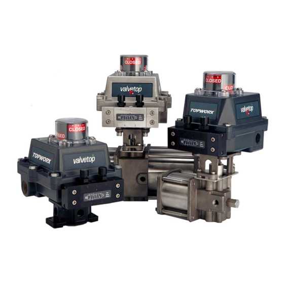
Valvetop D-Series with FF Option
™
F
OUNDATION
Installation, Operation & Maintenance Manual
Table of Contents
2
Quick Installation Guide
2
Installation
4
4
5
Electrical Connection
6
FF Operation
8
Troubleshooting and Maintenance
10
Appendix A: FF Technology
16
18
Resource Block DD Menu Structure
20
21
Transducer Block DD Menu Structure
26
27
29
31
35
™
Fieldbus
™
Advertisement
Table of Contents

Related Manuals for Emerson DXP-FF


Summary of Contents for Emerson DXP-FF
-
Page 1: Table Of Contents
Valvetop D-Series with FF Option ™ ™ Fieldbus OUNDATION Installation, Operation & Maintenance Manual Table of Contents Introduction Quick Installation Guide Installation Storage Pneumatic Connection Electrical Connection FF Operation Troubleshooting and Maintenance Appendix A: FF Technology Appendix B: Resource Block Resource Block DD Menu Structure Appendix C: Transducer Block Transducer Block DD Menu Structure... -
Page 2: Introduction
Verify calibration by actuating valve open and closed several times NOTE: Switches can be set using calibration switch without FF connection by using any 9-32VDC power source. Step 5 - Commission DXP-FF a) Connect single DO to Channel 5 No DI needed - Readback_D provides the actual valve position •... -
Page 3: Installation
www.topworx.com Installation on Actuator Orientations, Normal and Reverse Acting Normal acting is full CW when the process valve is closed and CCW when the process valve is open. Reverse acting is full CW when the process valve is open and CCW when the process valve is closed. 90°... -
Page 4: Storage
D-Series with FF Option Installation, Operation & Maintenance 502.969.8000 Installation on Actuator (continued) Mounting TopWorx has numerous mounting bracket kits available to meet your specific application, whether rotary or linear. Consult your local distributor or factory representative for ordering information. The illustration shows a direct Namur mount on a quarter turn valve. - Page 5 www.topworx.com Pneumatic Hookup Procedures Prior to connecting the supply air to the spool valve, flush the system to remove any debris or contaminates. Galva- nized pipe can easily flake and contaminate the system and therefore is not recommended. A 40 micron point of use filter at every device is recommended.
- Page 6 D-Series with FF Option Installation, Operation & Maintenance 502.969.8000 Electrical / FF Connections The F Fieldbus Sensor Communications Module (SCM-FF) combines integral switch relays for position OUNDATION sensing with F Fieldbus communications and pilot valve output drivers. OUNDATION Pilot Valve Wiring Single Pilot Valve ·...
- Page 7 www.topworx.com Calibration of Target / Feedback Calibration of the F Fieldbus SCM-FF OUNDATION Never perform calibration procedure unless area is known to be safe. · For Intrinsically Safe models, unit must be wired in accordance with Control Drawing S-K088A, or I.S. components may be damaged.
- Page 8 D-Series with FF Option Installation, Operation & Maintenance 502.969.8000 Section 2: Operation This section of the manual provides operational information for configuring the SCM-FF device on the Fieldbus Host Control System. This section includes both required Control Configuration and OUNDATION optional Monitoring Configuration information.
- Page 9 www.topworx.com Alarm Configuration (Optional) Discrete Input (DI) Block may be configured for monitoring internal Device Alarms within the Control Strategy of the Host System. The Internal Device Alarms can be monitored using a Discrete Input (DI) Block with the Channel Parameter assignment of 13.
- Page 10 D-Series with FF Option Installation, Operation & Maintenance 502.969.8000 Section 3: Maintenance This Section provides information on Troubleshooting and Component Replacement for the DXP-FF. Troubleshooting Description of Problem Possible Cause Possible Solution Red or green LED does not illuminate when...
- Page 11 www.topworx.com...
- Page 12 D-Series with FF Option Installation, Operation & Maintenance 502.969.8000...
- Page 13 www.topworx.com Component Replacement Manifold O-rings, Piezoelectric Buna Pilot Device Inserts M4x35 RED Urethane Tubing (Supply) 10-32 Nylon Plug Used in Fail Closed Applications 4-40x.25 (x2) Bracket YELLOW 10-32 Nylon Black Orange Urethane Barb Fitting to V - to V+ Tubing (Work) Fail Closed Spool Valve Replacement Assemblies AV-BFCVA20...
- Page 14 D-Series with FF Option Installation, Operation & Maintenance 502.969.8000 Indicator Dome, Indicator / Dome Replacement 5 adjustable Polycarbonate 10-32 Captive screws, with keyed mask. Stainless (x4) Several rotation and form options. Indicator / Dome Replacement Kits AV-GB002 90º, Green/Open, Red/Closed, Buna O-Ring AV-YB002 90º, Yellow/Open, Black/Closed, Buna O-Ring AV-TB002...
- Page 15 www.topworx.com Sensor Communications Module (SCM-FF) Replacement Calibration Switch Std Operation Jumper Location CL OSE OPEN Auxilliary Input Terminals (Dry contacts only) WrtPrt SCM-FF Piezo Pilot - V2 + - V1 + Terminals Foundation Fieldbus Loop Single Pilot Terminals Dual Pilot FLAS H RESET + = Orange - = Black...
- Page 16 D-Series with FF Option Installation, Operation & Maintenance 502.969.8000 Appendix A: F Fieldbus Technology OUNDATION Blocks and the User Application The Fieldbus Foundation has defined a standard for building user applications. The Foundation standard is built around “Blocks.” Blocks are used to represent different types of functions that the device performs and provide a way of grouping different parameters and functionality together in an easy to understand framework.
- Page 17 www.topworx.com Fieldbus Topology OUNDATION General Purpose Power Supply w/ Terminator “ON” to power (1) Fieldbus segment T = Fieldbus Terminator Control System Terminator “ON” Intrinsically Safe Repeaters Power Supply w/ Terminator “ON” to power (1) Fieldbus segment Terminator “ON” Control System T = Fieldbus Terminator Isolators w/ Terminators “ON”...
-
Page 18: Appendix B: Resource Block
D-Series with FF Option Installation, Operation & Maintenance 502.969.8000 Appendix B: Resource Block The resource block contains the hardware specific characteristics associated with a device. It has no input or output parameters. This block of contained parameters includes such things as Manufacturer’s ID and revision information. - Page 19 www.topworx.com Complete Resource Block Parameter Listing (cont’d) SHED REMOTE OUT Time duration at which to give up on computer writes to function block Rout locations. Shed from Rout shall never happen when SHED REMOTE OUT = 0. FAULT_STATE Condition set by loss of communication to an output block, fault promoted to an output block or a physical contact.
- Page 20 D-Series with FF Option Installation, Operation & Maintenance 502.969.8000...
-
Page 21: Appendix C: Transducer Block
www.topworx.com The following is a list of bit selections for Channel 13. Simply select Appendix C: Transducer Block the appropriate bit to activate the desired functionality. 0x00, No Selection Transducer Block Initialization 0x01, Cycle Count There are several settings in the transducer block that should be set before 0x02, Time to Open commissioning of the SCM-FF. - Page 22 D-Series with FF Option Installation, Operation & Maintenance 502.969.8000 Transducer Parameters to be set before an application is configured. For a complete list of transducer parameters, refer to Page 24. *The timer accuracy for stroke time open and stroke time closed is 60mS minimum.
- Page 23 www.topworx.com Fieldbus Foundation Transducer Channel Architecture The SCM-FF has one transducer block with 13 channels. The 5 DI and 3 DO function blocks will link to these trans- ducer channels through the standard channel selection capability. (See Function Blocks) The 13 Transducer Channels are listed below. Transducer Channels Channels 10, 11 and 12 Notes on Channels...
- Page 24 D-Series with FF Option Installation, Operation & Maintenance 502.969.8000 Complete Transducer Parameter Listing...
- Page 25 www.topworx.com Complete Transducer Parameter Listing (cont.)
- Page 26 D-Series with FF Option Installation, Operation & Maintenance 502.969.8000...
-
Page 27: Appendix D: Discrete Output (Do) Block
www.topworx.com Appendix D: Discrete Output (DO) To use the READBACK_D values for the BACK CALCULATION OUTPUT Discrete OUTPUT Blocks (DO Block) DISCRETE parameter of the DO block, the following two options must be selected: There are 3 F Fieldbus standard DO blocks and 5 output channels. OUNDATION The DO blocks take discrete control data and translate it to actuation in the field. - Page 28 D-Series with FF Option Installation, Operation & Maintenance 502.969.8000 Complete Discrete Output Block Parameter Listing...
-
Page 29: Appendix E: Discrete Input (Di) Block
www.topworx.com Appendix E: Discrete Input (DI) Block Discrete INPUT Blocks (DI Block) Table 1: There are 5 Discrete Input Blocks available on the DI Channel Parameter Settings List SCM-FF. The DI block takes the manufacturer’s discrete input data, selected by channel number, and makes it available to other function blocks at its output. - Page 30 D-Series with FF Option Installation, Operation & Maintenance 502.969.8000 Complete Discrete Input Block Parameter Listing...
-
Page 31: Appendix F: Dimension & Assembly Drawings
www.topworx.com Appendix F: Dimension and Assembly Drawings Valvetop DXP MATERIALS OF CONSTRUCTION Illustration #4 Cast A360 aluminum with dichro- mate conversion coating inside & Enclosure MINIMUM 2.5" REQUIRED CLEARANCE out, epoxy coated exterior rated for IN ORDER TO DISINGAGE THE SHAFT FROM THE ID BUSHING 250 hrs salt spray per ASTM B117 AND REMOVE LID WHERE OPTIMUM CONDITIONS APPLY 304 Stainless Steel standard... - Page 32 D-Series with FF Option Installation, Operation & Maintenance 502.969.8000 Valvetop DXP - IIC Illustration #5 MATERIALS OF CONSTRUCTION Cast A360 aluminum with dichro- mate conversion coating inside & Enclosure out, epoxy coated exterior rated for 250 hrs salt spray per ASTM B117 304 Stainless Steel standard Fasteners 316 Stainless Steel optional...
- Page 33 www.topworx.com Valvetop DXS Illustration #6 MATERIALS OF CONSTRUCTION MINIMUM 2.5" REQUIRED CLEARANCE IN ORDER TO DISINGAGE THE SHAFT FROM THE ID BUSHING Cast 316 Stainless Steel Enclosure AND REMOVE LID WHERE OPTIMUM CONDITIONS APPLY 304 Stainless Steel standard Fasteners 316 Stainless Steel optional 304 Stainless Steel standard Shaft 316 Stainless Steel optional...
- Page 34 D-Series with FF Option Installation, Operation & Maintenance 502.969.8000 Valvetop DXR Illustration #7 MATERIALS OF CONSTRUCTION MINIMUM 2.5" REQUIRED CLEARANCE IN ORDER TO DISINGAGE THE SHAFT FROM THE ID BUSHING AND REMOVE LID WHERE OPTIMUM CONDITIONS APPLY ® Valox Enclosure 304 Stainless Steel standard Fasteners 316 Stainless Steel optional...
-
Page 35: Appendix G: Specifications & Reference Data
www.topworx.com Appendix G: Specifications and Reference Data Table 1. Intrinsically Safe Entity Parameters Table 3. Fieldbus Specifications Table 2. Electrical Specifications Safe Use Special Conditions of Safe Use (All installations) Clean only with a damp cloth to prevent possibility of electrostatic discharge. For Explosion Proof installations, the internal ground connection shall be used and the external ground connection, if supplied in addition, is supplemental bonding allowed where local authorities permit, or is required. - Page 36 D-Series with FF Option Installation, Operation & Maintenance 502.969.8000 Certifications & Approvals 0518 AREA CERTIFICATION Ex ia IIC T4 –40°C ≤ Tamb ≤ 80°C, IP67 DEMKO 02ATEX0223499X Ui:24Vdc, Ii:250mA, Pi:1,2W, Ci:2.5nF, Li:129µH Class I Div 1&2 Groups A,B,C,D; T4; Type 4, 4X Intrinsically Safe / Securite Intrinsique Electrical Rating: 9-32Vdc, 20mA Class I Div 1 Groups C,D;...
- Page 37 www.topworx.com Warranty...
- Page 38 D-Series with FF Option Installation, Operation & Maintenance 502.969.8000 NOTES:...
- Page 39 www.topworx.com NOTES:...
- Page 40 The Emerson logo is a trademark and a service mark of Emerson Electric Co. ©2014 Emerson Electric Co. ©2014 TopWorx™, All rights reserved.TopWorx, Valvetop, and GO Switch are trademarks of TopWorx™. All other marks used in this document are the property of their respective owners.
Need help?
Do you have a question about the DXP-FF and is the answer not in the manual?
Questions and answers