Table of Contents
Advertisement
Quick Links
Advertisement
Table of Contents

Subscribe to Our Youtube Channel
Related Manuals for moyno G2


Summary of Contents for moyno G2
- Page 2 SERVICE MANUAL ® MOYNO 2000 Pumps G2 Open Throat Models G3 Bridge Breaker Models Version 3 Models...
-
Page 3: Table Of Contents
4-23. Packing Removal ......7 Note: This service manual outlines installation, operation and maintenance proce- dures for the open throat “G2” and bridge breaker “G3” models of the Moyno 2000 pump. For information on the flanged (G1) models of the Moyno 2000 pump, refer to the G1 Service Manual, or contact your nearest Moyno pump representative. -
Page 4: Introduction
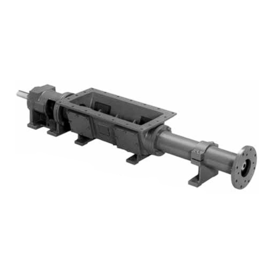
It represents the next genera- tion of the world’s most versatile pump. The Moyno 2000 Pump is a progressing cavity pump. The pumping action is created by a single helical rotor rolling eccentrically in the double helix of the stator. The rotor in conjunction with the stator forms a series of sealed cavities Figure 1-1. -
Page 5: Trim Code
Standard charge port. This will allow the rotor and stator to be re- stator materials used in the Moyno 2000 pump are as fol- moved without having to remove the complete pump from lows: the base. -
Page 6: Shaft Alignment
Page 3 For maximum rigidity and lower noise levels the base plate should be grouted to the foundation after the anchor bolts have been evenly tightened. A good grade of non- shrink grout is recommended. The spaces between the base plate and the foundation around the shims should also be filled with grout. -
Page 7: Packing Leakage
The entire pump need not be disassembled to replace the packing. The Moyno 2000 pump has been designed for a minimum Briefly, replace as follows: of maintenance, the extent of which is routine adjustment and lubrication of packing. -
Page 8: Lubrication
SAE 30 or 40 weight oil. 4-9. DISASSEMBLY OF G2 OPEN THROAT PUMP Note: In the following G2 disassembly instructions, the part reference numbers are from fig. 4-7. Note: The following instructions cover ONE procedure for disassembling all pump components. -
Page 9: Rotor Removal
Page 6 6b.Hold stator (44) with pipe or strap wrench and turn 4-15. Drive Shaft and Bearings Removal drive shaft (4) clockwise to force stator (44) off rotor (37). 1. Complete sections 4-9 thru 4-13. 7. Check rotor (37) and stator (44) for wear. See Rotor (4-30) and Stator (4-31) for instructions. -
Page 10: Torque Limiter Removal
Page 7 4-19. Torque Limiter Removal 7. Pull both shafts (17 and 18) from bearings (10) and bearing support (11). 1. Complete Section 4-17, steps 1-3. 4-23. Packing Removal 2. Complete Section 4-18, steps 1-3. 1. Complete section 4-17. 3. Loosen set screw on torque limiter (3), and remove key from shaft (17). -
Page 11: Seals
& Packing (Dubois Chemical, Inc.) c. The base surface metal is not pitted or corroded. 4. Rotors may be sent to Moyno or any other competent plating shop. Rotors should be stripped and replated to 4-35. Packing Installation standard dimensions, then buffed. -
Page 12: Bearing Housing/Suction Housing Assembly
Page 9 CAUTION: Always use a proper packing tamper tool to Note: The tapered bearings are designed such that when install packing. Do not use a pointed or properly installed there may be a very slight end play sharp tool, as damage to the packing mate- in the bearings (bearing spacer halves may slip freely rial or drive shaft could result. -
Page 13: Rotor Gear Joint And Conveyor Assembly
Page 10 4. Insert primary thrust plate (25) into rotor head, bored holes of shaft adapter (23). Check that the O-ring is flat side first. Thrust plate and rotor head surfaces must be properly seated. Thread four socket head screws (O) flush to assure proper assembly and operation of the pumps through shaft adapter and into threaded holes in drive (See fig. -
Page 14: Drive End Gear Joint Assembly
Page 11 14. Excess grease in the assembly will be purged from 4-41. Stator Support/Discharge Assembly the vent hole while the socket head screws are tightened. Tighten set screw (Q) in shell. Move the free end of con- 1. Place top of stator support(s) (41) over stator and fas- veyor assembly in a circular motion to assure that the joint is ten to bottom half of stator supports using hex head screws free and assembled properly. -
Page 15: Paddle Assembly Installation
Page 12 3. Thread packing glands (25) into threaded portions of 4. Place drive sprocket (33) on drive shaft of pump with bearing retainer (28). set screws facing away from bearing housing. 4. Bolt spacer (30) and bearing retainer (28), with small 5. -
Page 16: Packing Specification
4-54. PACKING SPECIFICATION E — Extension tube with extended auger F — Extended drive shaft (for back stop or large pulley) Standard packing on all Moyno 2000 pumps consists of G — Ceramic coating braided PTFE fibers impregnated with ultrafine graphite. -
Page 17: Standard Hardware For G2 Open Throat
Page 14 4-58. STANDARD HARDWARE FOR G2 OPEN THROAT TORQUE GUIDELINES CHART Note: Torque values are from the Industrial Fasteners Institute and Craftsman Corp. -
Page 18: Selecting The Correct Part
4-59. SELECTING THE CORRECT PART FOR YOUR MOYNO 2000 PROGRESSING CAVITY PUMP PUMP MODEL SELECTION Table 4-1 G-2 Parts List: Select G2 part number by Drive End (2G036G2 CDQ AAA) and Type Designation (Page 16) (2G036G2 CDQ AAA) where listed. -
Page 19: Parts List For G2 Open Throat
Page 16 4-60. PARTS LIST FOR G2 OPEN THROAT. Table 4-1. G2 Parts List... - Page 20 Page 17 FOLD OUT FOR EXPLODED VIEW OF PUMP Notes...
- Page 21 Page 18...
- Page 22 Page 19 Figure 4-7. G2 open throat pump exploded view.
-
Page 23: Standard Hardware For G3 Bridge Breaker
Page 20 4-61. STANDARD HARDWARE FOR G3 BRIDGE BREAKER 4-62. PARTS LIST FOR G3 BRIDGE BREAKER Table 4-6. G3 Parts List... - Page 24 Page 21 FOLD OUT FOR EXPLODED VIEW OF PUMP Table 4-7. Shaft Sleeve Arrangement Table 4-8. Shaft Sleeve Conversion Kit** Figure 4-8. Stuffing Box Rework Dimensions for Shaft Sleeve Option.
-
Page 25: Conversion From G2 To G3
Page 22 4-63. CONVERSION FROM G2 TO G3 To convert a Moyno 2000 Pump from G2 to G3 construc- tion requires that the top of the bearing housing (14, fig. 4-7) be machined flat and that two drilled and tapped holes be added for mounting the bridge breaker bearing support. - Page 26 Page 23 Figure 4-10. G3 bridge breaker exploded view.
-
Page 27: Shaft Sleeve Arrangement
Page 24 Figure 4-11. Shaft Sleeve Arrangement 4-64. SHAFT SLEEVE ARRANGEMENT Some pumps have a sleeve installed on the drive shaft to receive any possible wear caused by the packing. See sleeve kit (46, fig. 4-11), and the cross section illustration (fig. -
Page 28: Troubleshooting
Page 25... - Page 29 Monel is a trademark of INCO Alloy Corp. Hypalon and Teflon are trademarks of E.I. DuPont de Nemours and Company Thiokol is a trademark of Morton Thiokol Inc. Printed in U.S.A. Moyno, Inc. is a Unit of Robbins & Myers, Inc.
Need help?
Do you have a question about the G2 and is the answer not in the manual?
Questions and answers