Table of Contents
Advertisement
Quick Links
Advertisement
Table of Contents

Related Manuals for moyno 1000


Summary of Contents for moyno 1000
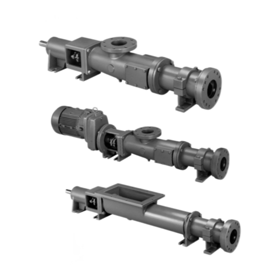
- Page 1 SERVICE MANUAL ® MOYNO 1000 Pumps...
-
Page 2: Table Of Contents
TABLE OF CONTENTS Page Page 4-21a. Mechanical Seals…………….. 7 1-1. INTRODUCTION………………………………... 4-22. Packing…………………………. 7 1-2. GENERAL…………………………………1 4-23. Rotor…………………………….. 7 1-3. SCOPE…………………………………….1 4-24. Stator……………………………. 7 1-4. NAMEPLATE DATA…...…………………1 4-25. All Other Parts………………….. 7 1-5. Pump Rotation………………… 1 4-26. ASSEMBLY………………………………7 1-6. Model Number………………… 1 4-26a. -
Page 3: Introduction
1000 PUMPS 1-1. INTRODUCTION 1-2. GENERAL The Moyno 1000 pump is the most versatile positive displacement pump available. Its design parameters have been proven in thousands of applications over the past 60 years, and it is backed by this same half century-plus of experience in application and manufacturing know-how. -
Page 4: Installation
and other metallic parts in contact with the material INSTALLATION being pumped. 2-1. The third letter indicates the material of the stator. It 2-2. GENERAL identifies only the stator material and not that of the tube in which the stator is placed. The tube, a non-wetted Accessibility to the pump and adequate clearance should part, is always alloy steel. -
Page 5: Coupling Connected Units
3-2. INTIAL CHECK 4-2. GENERAL Before putting the pump into operation, the following The Moyno 1000 pump has been designed for a items should be checked to ensure that each piece of minimum of maintenance, the extent of which is routine... -
Page 6: Packing Replacement
Section 4-26. 4-6. DRIVE SHAFT AND ROTOR-EXTENDED LIFE PROVISION The heads on the drive shaft and rotor of Moyno 1000 pumps are manufactured with two sets of drive pin holes Figure 4-2. Packing Removal Tool located 90 degrees apart. -
Page 7: Suction Chamber Removal
4-14. Drive Shaft Removal Shaft Drive Models (one-piece shaft, not close-coupled) 4-10. Suction Chamber Removal The Moyno 1000 pump is designed so that the stuffing 1. On standard and close-coupled models, remove box (1000), packing gland, packing, and bearings (D or E) four suction chamber bolts and lock washers (M) are removed as an assembly with the drive shaft. -
Page 8: Bearing Removal
4-19. Bearings. As described in Section 4-5 on Bearing Lubrication, ball bearings (E) are sealed by the The Moyno 1000 close-coupled pump is designed so manufacturer and are not designed to be relubricated and that the stuffing box, packing gland, and packing are reused. -
Page 9: Packing
2. If the measured crest-to-crest diameter is within .010 in. of the standard value, the rotor is reusable provided that: 1. Slide stuffing box (1000) on to drive shaft (6000), large flanged end first. a. the rotor pin holes are not excessively worn. -
Page 10: Two-Piece Shaft Models
6) Place assembled drive shaft into bearing housing. in groove in drive end of bearing housing. Proceed to 4- Secure by inserting second bearing housing snap ring in groove in stuffing box end of bearing housing. 4-27b. Tapered Roller Bearing Models 4-26b. -
Page 11: Shaft Installation
4-30a. Mechanical Seal Installation (Single Seal) 1. Install the stationary component (seat and O-ring) of mechanical seal (6950) in seat of seal retainer (1000). 2. Position the seal housing in the bearing housing (1). 3. Slide the rotating component (spring and rotating seat) onto the drive shaft. -
Page 12: Suction Chamber
2. Fold other end of seal back towards center of connecting rod. Note: 1. Before installation of stator, lubricate rotor and/or inside of stator with water or glycerine to facilitate 3. Spread head snap ring (J) ends and place on drive installation. -
Page 13: Storage
4-39. RECOMMENDED SPARE PARTS INSTALLATION instructions. (Sections 2-1 through 2-9) 4. Review OPERTAION instructions per Sections 3-1 The Moyno 1000 pump has been designed and built to through 3-4. minimize overall operating costs. All wearable parts are replaceable. A recommended inventory of spare parts is 4-37. - Page 14 CLAMP RING BOLT CHART A2A B2A A1D A1E D4D A1B B1B A1C B2C A2D A2E E4D Ref. A2B B2B A2C D4C B1D B1E D4E No. Description D4B E4B B1C E4C B2D B2E E4E Suction End Bolts M10x30 (AA076) M12x50 (AA105) M12x55 (AA106) M12x35 (AA102) M12x55 (AA106)
-
Page 15: Standard Hardware List- Standard And Open Throat Models
NOTE: It is suggested that the standard hardware below be purchased at your local hardware outlet. Items can be purchased from Moyno Inc. The number in ( ) is Moyno’s reference 4-41. STANDARD HARDWARE LIST - number only. STANDARD AND OPEN THROAT MODELS... -
Page 16: Exploded Views
4-42. STANDARD HARDWARE LIST – CLOSE-COUPLED MODELS MODELS B1H, B2H Ref. B1J, B2J No. Description B1K,B2K C. Name Plate Drive Screw No. 2 x 3” No. 2 x 3” No. 2 x 3” No. 2 x 3” (Steel, round head, type U) (AN005) (AN005) (AN005) -
Page 17: Close-Coupled Models
4-45. STANDARD MODEL – ROLLER BEARING DESIGN DRIVE END = Used on Models A4A, A4B, A4C, A4D, A4E, A4F = Used on Models A1B, A1C, A1D, A2A, A2B, A2C, A2D, A4A, A4B, D4B, D4C, D4D... - Page 18 4-46. CLOSED-COUPLED MODELS = Used on Models B4A, B4B, B4C, B4D, B4E = Used on Models B1B, B1C, B1D, B2A, B2B, B2C, B2D, B4A, B4B, E4B, E4C, E4D,...
-
Page 19: Open Throat Models
4-47. OPEN THROAT MODELS... -
Page 20: Parts List
CC A2A0110 CC A2A0110 CC A2A0110 0900 PACKING GLAND CD/SS SC A2A0910 SC A2A0910 SC A2A0910 SC A2A0910 SC A2A0910 1000 STUFFING BOX CC A2A1010 CC A2A1010 CC A2A1010 CC A2A1010 CC A2A1010 SC A2A1010 SC A2A1010 SC A2A1010 SC A2A1010... - Page 21 MS A1F0700 MS A1H0700 0900 PACKING GLAND CD/SS SC A1A0910 SC A1D0910 SC A1D0910 SC A1F0910 SC A1F0910 SC A1H0910 1000 STUFFING BOX CC A2A1010 CC A1D1010 CC A1D1010 CC A1F1010 CC A1F1010 CC A1H1010 SC A2A1010 SC A1D1010 SC A1D1010...
- Page 22 MS A1F0700 MS A1F0700 0900 PACKING GLAND CD/SS SC A1D0910 SC A1D0910 SC A1D0910 SC A1D0910 SC A1F0910 SC A1F0910 1000 STUFFING BOX CC A1D1010 CC A1D1010 CC A1D1010 CC A1D1010 CC A1F1010 CC A1F1010 SC A1D1010 SC A1D1010 SC A1D1010...
- Page 23 MS A1H0700 0900 PACKING GLAND CD/SS SC A1F0910 SC A1F0910 SC A1H0910 SC A1H0910 SC A1H0910 SC A1H0910 SC A1H0910 1000 STUFFING BOX CC A1F1010 CC A1F1010 CC A1H1010 CC A1H1010 CC A1H1010 CC A1H1010 CC A1H1010 SC A1F1010 SC A1F1010...
- Page 24 CC B1D0100 CC B2A0100 0900 PACKING GLAND CD/SS SC A2A0910 SC A2A0910 SC A2A0910 SC A2A0910 SC A1D0910 SC A2A0910 1000 STUFFING BOX CC A2A1010 CC A2A1010 CC A2A1010 CC A2A1010 CC A1D1010 CC A2A1010 SC A2A1010 SC A2A1010 SC A2A1010...
- Page 25 CC B1F0100 CC B1D0100 0900 PACKING GLAND CD/SS SC A2A0910 SC A1D0910 SC A1D0910 SC A1D0910 SC A1F0910 SC A1D0910 1000 STUFFING BOX CC A2A1010 CC A1D1010 CC A1D1010 CC A1D1010 CC A1F1010 CC A1D1010 SC A2A1010 SC A1D1010 SC A1D1010...
- Page 26 CC B1H0100 CC B1F0100 0900 PACKING GLAND CD/SS SC A1D0910 SC A1F0910 SC A1F0910 SC A1F0910 SC A1H0910 SC A1F0910 1000 STUFFING BOX CC A1D1010 CC A1F1010 CC A1F1010 CC A1F1010 CC A1H1010 CC A1F1010 SC A1D1010 SC A1F1010 SC A1F1010...
- Page 27 CC B1H0100 CC B1H0100 0900 PACKING GLAND CD/SS SC A1F0910 SC A1H0910 SC A1H0910 SC A1H0910 SC A1H0910 SC A1H0910 1000 STUFFING BOX CC A1F1010 CC A1H1010 CC A1H1010 CC A1H1010 CC A1H1010 CC A1H1010 SC A1F1010 SC A1H1010 SC A1H1010...
- Page 28 0100 DRIVE ADAPTOR CD/SS CC B1H0100 CC B1H0100 CC B1H0100 0900 PACKING GLAND CD/SS SC A1H0910 SC A1H0910 SC A1H0910 1000 STUFFING BOX CC A1H1010 CC A1H1010 CC A1H1010 SC A1H1010 SC A1H1010 SC A1H1010 1000 SEAL CD/SS SC A1H1011...
- Page 29 MS A1F0700 MS A1F0700 MS A1F0700 0900 PACKING GLAND CD/SS SC A1D0910 SC A1D0910 SC A1F0910 SC A1F0910 SC A1F0910 1000 STUFFING BOX CC A1D1010 CC A1D1010 CC A1F1010 CC A1F1010 CC A1F1010 SC A1D1010 SC A1D1010 SC A1F1010 SC A1F1010...
- Page 30 MS A1H0700 MS A1H0700 0900 PACKING GLAND CD/SS SC A1F0910 SC A1H0910 SC A1H0910 SC A1H0910 SC A1H0910 SC A1H0910 1000 STUFFING BOX CC A1F1010 CC A1H1010 CC A1H1010 CC A1H1010 CC A1H1010 CC A1H1010 SC A1F1010 SC A1H1010 SC A1H1010...
- Page 31 MS A1H0700 0900 PACKING GLAND CD/SS SC A2A0910 SC A2A0910 SC A1D0910 SC A1D0910 SC A1F0910 SC A1F0910 SC A1H0910 1000 STUFFING BOX CC A2A1010 CC A1A1010 CC A1D1010 CC A1D1010 CC A1F1010 CC A1F1010 CC A1H1010 SC A2A1010 SC A1A1010...
- Page 32 CC B2A0110 CC B2A0110 CC B1D0110 CC B1D0110 0900 PACKING GLAND CD/SS SC A2A0910 SC A2A0910 SC A1D0910 SC A1D0910 1000 STUFFING BOX CC A2A1010 CC A2A1010 CC A1D1010 CC A1D1010 SC A2A1010 SC A2A1010 SC A1D1010 SC A1D1010 1000 SEAL...
-
Page 33: Troubleshooting Chart
4-49. TROUBLESHOOTING CHART... - Page 34 Your Authorized Service Distributor is: © 2002 by Moyno, Inc. Printed in U.S.A. ® Moyno is a registered trademark of Moyno, Inc. Moyno, Inc. is a Unit of Robbins & Myers, Inc.
Need help?
Do you have a question about the 1000 and is the answer not in the manual?
Questions and answers