Table of Contents
Advertisement
Quick Links
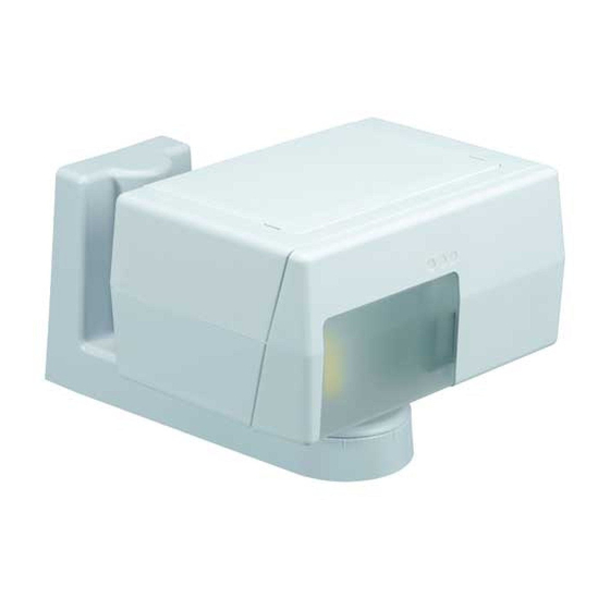
DT900AM Series DUAL TEC
and Light Industrial Applications—Installation Instructions
Step 1
Select mounting height.
30 cm (12") minimum
Optimal
Mounting
Height
2.3m (7'6")
Mounting Location Guidelines
• Avoid direct or reflected sunlight
• Aim sensor away from windows, heating/
cooling devices or large moving objects.
• Sensor must have a clear line-of-sight to
protected area
Step 5
Locate correct sensor range scale
and rotate Vertical Adjustment Screw
until the diamond corresponds to the
sensor mounting height (coarse
adjust).
NOTE: Fine adjust may be needed during
walk-test. (See Troubleshooting section.)
Step 9
Unfasten screws and remove mount-
ing plate from sensor. If required,
remove the knockout to allow wire
entry via electric metallic tubing or
surface wiring conduit.
Step 13
Hang the sensor on the mounting
plate hooks and fasten with the two
mounting plate screws.
NOTE: Secure
wires to
mounting plate
with tie wraps.
Step 17
Tighten horizontal locking screw in
sensor support base.
Step 21
For fine horizontal adjustment, loosen
the PIR horizontal fine locking screw
on the PCB.
Step 2
Carefully push screwdriver into slots
to disengage latches and open top
cover.
Step 6
Set switch S3 to establish the
sensitivity best suited to your appli-
cation.
SENSITIVITY
S3
HIGH (Pulse Count 1)
H*
NORMAL (Pulse Count 2)
N
LOW (Pulse Count 3)
L**
*Factory default setting; recommended setting
for DT906AM. **Not connected.
Step 10
Attach mounting plate to wall at
desired height, using four screws
(not supplied).
Step 14
Wire the
unit as
shown.
Use
0.8 - 1.5 mm
(22-16 AWG).
Step 18
Apply power to the sensor, and all
the LED's will start flashing rapidly.
Wait 90 seconds for the power-up
self-test to finish, at which point, if
there is no motion in the detection
area, all the LED's will be off, and the
sensor will be ready for walk testing.
If the three LED's do not go off after
90 seconds, refer to the Trouble-
shooting section.
Step 22
Rotate the horizontal fine adjust knob
to the desired position.
NOTE: Fine adjustment allows for small
changes (3 degrees right or left) between
coarse settings.
Motion Sensor for Commercial
®
Step 3
DT906AM ONLY: Firmly insert
screwdriver into slot in arrow and
rotate PIR Mirror Selector to the
correct range.
Step 7
Select INFORMER
mode with switch
®
S2, if desired. (See INFORMER Mode
section).
OFF
OFF*
MODE 1
MODE 2
*Factory default setting (not connected).
Step 11
Install M5 (#10) screw (not supplied)
in wall 1.9 cm (3/4") below mounting
screw, as shown, for tamper activa-
tion.
1.9 cm (3/4")
Step 15
Loosen horizontal locking screw in
sensor support base.
Step 19
Turn the microwave potentiometer
counterclockwise to decrease the
microwave range to minimum.
During walk-test, gradually turn the
potentiometer clockwise increasing
microwave sensitivity until the
desired range is obtained.
Step 23
Tighten the horizontal fine locking
screw on the PCB.
Step 4
Set switch S4 to establish microwave
range.
MODEL
RANGE
DT906AM 61 m (200')
DT906AM 37 m (120') CLOSED
DT900AM 24.4 m (80') OPEN*
DT900AM
15 m (50')
*Factory default setting.
Step 8
Carefully push screwdriver into slot
to disengage latch and remove
bottom cover.
S2
1
2
Step 12
Pull about 30 cm (12") of wire from
wall through the opening in the
mounting plate and route wire to the
terminal strip.
Step 16
Grasp housing and rotate it to the
desired position (coarse adjust). If
fine adjust is needed see Steps 21-
23.
NOTE: Reference marks = 5° change.
Step 20
Walk-test the sensor to check for
adequate detection coverage and to
verify the sensor is fully functional.
Depending on the selected sensitiv-
ity level, the sensor will alarm after
taking between 2 and 4 steps in the
detection pattern.
NOTE: If an on-going trouble, mask or
INFORMER condition occurs, the LEDs will
display a pattern that identifies the trouble.
(See the Troubleshooting section).
Step 24
Remove the jumper at J4 on the PCB
to disable the LEDs after walk-
testing, and complete installation by
closing the top cover and replacing
the bottom cover.
MIRROR
Switch S4
Selector
OPEN*
200' *
120'
N/A
CLOSED
N/A
Advertisement
Table of Contents

Related Manuals for Honeywell DT906AM


Summary of Contents for Honeywell DT906AM
- Page 1 Mounting Location Guidelines DT906AM 61 m (200’) OPEN* 200’ * • Avoid direct or reflected sunlight DT906AM 37 m (120’) CLOSED 120’ • Aim sensor away from windows, heating/ DT900AM 24.4 m (80’) OPEN* cooling devices or large moving objects.
- Page 2 5% to 95% relative humidity (non-condensing) illuminate, the sensor is faulty and should be replaced. Copyright 2006 Honeywell International Inc. Honeywell, IntelliSense, DUAL TEC and INFORMER are registered trademarks Please contact your local authorised Honeywell 5-051-367-00 Rev A of Honeywell International Inc.
Need help?
Do you have a question about the DT906AM and is the answer not in the manual?
Questions and answers